EP0468076A1 - Dispositif d'élargissement de tubes - Google Patents
Dispositif d'élargissement de tubes Download PDFInfo
- Publication number
- EP0468076A1 EP0468076A1 EP90114371A EP90114371A EP0468076A1 EP 0468076 A1 EP0468076 A1 EP 0468076A1 EP 90114371 A EP90114371 A EP 90114371A EP 90114371 A EP90114371 A EP 90114371A EP 0468076 A1 EP0468076 A1 EP 0468076A1
- Authority
- EP
- European Patent Office
- Prior art keywords
- sleeve
- expansion sleeve
- expanding
- expansion
- tube
- Prior art date
- Legal status (The legal status is an assumption and is not a legal conclusion. Google has not performed a legal analysis and makes no representation as to the accuracy of the status listed.)
- Withdrawn
Links
- 239000000523 sample Substances 0.000 claims abstract description 10
- 229920001971 elastomer Polymers 0.000 claims description 5
- 239000000806 elastomer Substances 0.000 claims description 5
- 239000000463 material Substances 0.000 claims description 4
- 238000004904 shortening Methods 0.000 claims description 3
- 239000011324 bead Substances 0.000 claims 1
- 238000006073 displacement reaction Methods 0.000 claims 1
- 239000013013 elastic material Substances 0.000 abstract 1
- 238000010438 heat treatment Methods 0.000 description 5
- 238000007789 sealing Methods 0.000 description 5
- 230000007704 transition Effects 0.000 description 5
- 230000000149 penetrating effect Effects 0.000 description 2
- 230000002787 reinforcement Effects 0.000 description 2
- 238000005096 rolling process Methods 0.000 description 2
- 238000010276 construction Methods 0.000 description 1
- 230000007797 corrosion Effects 0.000 description 1
- 238000005260 corrosion Methods 0.000 description 1
- 238000005336 cracking Methods 0.000 description 1
- 239000007788 liquid Substances 0.000 description 1
- 238000000034 method Methods 0.000 description 1
- 238000003825 pressing Methods 0.000 description 1
- 238000013022 venting Methods 0.000 description 1
- 238000003466 welding Methods 0.000 description 1
Images


Classifications
-
- B—PERFORMING OPERATIONS; TRANSPORTING
- B21—MECHANICAL METAL-WORKING WITHOUT ESSENTIALLY REMOVING MATERIAL; PUNCHING METAL
- B21D—WORKING OR PROCESSING OF SHEET METAL OR METAL TUBES, RODS OR PROFILES WITHOUT ESSENTIALLY REMOVING MATERIAL; PUNCHING METAL
- B21D39/00—Application of procedures in order to connect objects or parts, e.g. coating with sheet metal otherwise than by plating; Tube expanders
- B21D39/08—Tube expanders
- B21D39/20—Tube expanders with mandrels, e.g. expandable
- B21D39/203—Tube expanders with mandrels, e.g. expandable expandable by fluid or elastic material
Definitions
- the invention relates to a device for expanding a tube with a probe which can be inserted into the tube and which contains a radially expandable expansion sleeve made of an elastically highly deformable material.
- Devices for expanding a tube are used, for example, for the gap-free connection of a heating tube in the tube sheet of a steam generator or for the so-called "sleeving" of tubes.
- the invention is based on the object of specifying a device for expanding a tube with which a largely uniform expansion and a smooth transition between the expansion area and the non-expanded area can be achieved over the largest possible expansion length.
- contact with a liquid should be avoided in the widening area and it should also be possible to reach hard-to-reach places inside a pipe.
- the expansion sleeve consists of an elastomer.
- the expansion sleeve preferably comprises a central area with an approximately constant wall thickness, which is adjoined by an area with a continuously increasing wall thickness.
- the expanding sleeve is supported with its opposite end edge regions in receiving sleeves which are connected to one another in a tensile manner via a central pull rod.
- This pull rod is preferably also used to supply the pressure medium to the inner surface of the expansion sleeve.
- the receiving sleeve is preferably embedded with its front edge regions in a hollow cylindrical recess located between the pull rod and the receiving sleeve.
- means are provided which, in the event of an axial shortening of the expansion sleeve caused by pressurization, bring about an axial tracking of at least one of the two receiving sleeves.
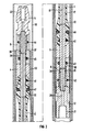
- a device for expanding a tube contains an expanding sleeve 2 made of a material with high elastic deformability speed, preferably an elastomer with a hardness between 90 Shore and 100 Shore, for example Fibroflex (trademark of FIBRO).
- the expansion sleeve 2 is supported with its front edge areas in receiving sleeves 4 and 6.
- the receiving sleeves 4 and 6 are fixed by a pull rod 16 screwed to an end sleeve 12.
- the pull rod 16 is also designed as a probe head 10 and is provided with a shoulder in the region of the probe head 10, on which the receiving sleeve 4 is supported.
- the expansion sleeve 2 has in its central region 3 an approximately hollow cylindrical shape with a relatively small wall thickness. With an expansion probe for a 7/8 "tube and an expansion length of approximately 50 mm, this wall thickness is approximately 1 mm with an outer diameter of approximately 9 mm.
- the pull rod 16 is provided with an axially inside continuous longitudinal channel 18 for a pressure medium, which is supplied via a bore 20 arranged in the end sleeve 12 and a threaded medium connection 21 for a hydraulic line.
- a threaded pin 22 provided with a sealing cone 23 is provided in the head part 10 of the pull rod 16 for venting and for closing the longitudinal channel 18.
- the pull rod 16 is provided in its area surrounded by the expansion sleeve 2 with a plurality of radial channels 30 and 32 through which the pressure medium from the longitudinal channel 18 passes between the pull rod 16 and the expansion sleeve 2. Sealing rings 40 and 41 prevent the pressure medium from penetrating into the spaces between the pull rod 16 and the receiving sleeves 4 and 6 and escaping to the outside.
- the expanding sleeve 2 is provided in the region of the edge of the receiving sleeve 4 or 6 surrounding it in a ring shape with an annular circumferential groove for receiving an O-ring 46 or 47.
- the O-rings 46 and 47 protect the expansion sleeve 2 from damage when the expansion sleeve 2 is squeezed into the cavities between the receiving sleeves 4 and 6 and the pipe to be expanded when pressure is applied.
- it is also reinforced in a bead-like manner in the vicinity of the O-rings 46 and 47.
- the expansion area is also limited by the O-rings 46 and 47.
- the expansion sleeve 2 comprises a central area 3 with an approximately constant small wall thickness, which is adjoined by an area with a continuously increasing wall thickness, which merges into the bead-like reinforcement. This measure creates a widening area with a widening that is as uniform as possible, which merges smoothly and smoothly into the unexpanded area of the tube.
- 14 compensation sleeves 8 and 9 are provided between the receiving sleeves 6 and 4 and the end sleeve 12 or a probe head.
- the probe head 14 is a separate part which is screwed to the end sleeve 12 via a pull rod 17.
- channels 34 and 36 respectively, which open into an annular cavity 35 and 37 surrounding the tie rod 17.
- the cavities 35 and 37 are each delimited by a shoulder 38 or 39 and by the probe head 14 screwed to the pull rod 17 or by the end sleeve 12. Sealing rings 42, 43, 44 and 45 prevent the pressure medium penetrating into the cavities 35 and 37 from escaping.
- the travel compensation sleeves 8 and 10 are axially displaceable in the direction of the expansion sleeve 2.
- a force is generated which is directed axially towards the center of the probe and which compensates for an axial shortening of the expansion sleeve 2 caused by the radial expansion of the expansion sleeve 2. This can prevent the expansion sleeve 2 from pulling out of the receiving sleeves 4 and 6 when pressure is applied, and leaks occur at the sealing rings 40 and 41, respectively, which result in the pressure medium escaping.
- the example of the figure shows the device for expanding a tube in a sleeve tube 52 arranged inside a heating tube 50 of a heat exchanger.
- pressure for example 1200 bar
- the expansion sleeve 2 is inflated and pressed between the O-rings 46 and 47 in their entire lying area 3 to the sleeve tube 52.
- the sleeve pipe 52 then lies against the heating pipe 50.
- a gap-free connection is created between the sleeve pipe 52 and the heating pipe 50 almost in the entire expansion area, which enables the two pipes to be welded subsequently.
- the entire expansion area is composed of a largely cylindrical area A opposite the central area 3 of the expansion sleeve and adjoining smooth transition areas B caused by the bead-like reinforcements of the expansion sleeve.
Landscapes
- Engineering & Computer Science (AREA)
- Mechanical Engineering (AREA)
- Non-Disconnectible Joints And Screw-Threaded Joints (AREA)
Priority Applications (1)
| Application Number | Priority Date | Filing Date | Title |
|---|---|---|---|
| EP90114371A EP0468076A1 (fr) | 1990-07-26 | 1990-07-26 | Dispositif d'élargissement de tubes |
Applications Claiming Priority (1)
| Application Number | Priority Date | Filing Date | Title |
|---|---|---|---|
| EP90114371A EP0468076A1 (fr) | 1990-07-26 | 1990-07-26 | Dispositif d'élargissement de tubes |
Publications (1)
| Publication Number | Publication Date |
|---|---|
| EP0468076A1 true EP0468076A1 (fr) | 1992-01-29 |
Family
ID=8204266
Family Applications (1)
| Application Number | Title | Priority Date | Filing Date |
|---|---|---|---|
| EP90114371A Withdrawn EP0468076A1 (fr) | 1990-07-26 | 1990-07-26 | Dispositif d'élargissement de tubes |
Country Status (1)
| Country | Link |
|---|---|
| EP (1) | EP0468076A1 (fr) |
Cited By (2)
| Publication number | Priority date | Publication date | Assignee | Title |
|---|---|---|---|---|
| WO1996035527A1 (fr) * | 1995-05-11 | 1996-11-14 | Siemens Aktiengesellschaft | Dispositif permettant d'elargir un tuyau |
| US5907965A (en) * | 1995-05-11 | 1999-06-01 | Siemens Aktiengesellschaft | Device for expanding a tube |
Citations (8)
| Publication number | Priority date | Publication date | Assignee | Title |
|---|---|---|---|---|
| FR1330224A (fr) * | 1962-05-08 | 1963-06-21 | Fives Lille Cail | Dudgeonnage hydraulique des tubes dans une plaque tubulaire |
| FR1365999A (fr) * | 1963-04-11 | 1964-07-10 | Fives Lille Cail | Dudgeonnage hydraulique de tubes dans une plaque tubulaire |
| FR1527073A (fr) * | 1967-04-14 | 1968-05-31 | Dudgeon flexible dilatable | |
| EP0041835A2 (fr) * | 1980-06-05 | 1981-12-16 | The Babcock & Wilcox Company | Elargissement de tubes |
| CA1152876A (fr) * | 1981-11-17 | 1983-08-30 | John A. Aikin | Distendeur hydraulique a vessie |
| BE902924A (fr) * | 1985-07-18 | 1986-01-20 | Cockerill Mech Ind Sa | Outil d'expansion hydraulique pour structure tubulaire |
| EP0177045A1 (fr) * | 1984-10-04 | 1986-04-09 | Westinghouse Electric Corporation | Mandrin de tuyau pour la dilatation hydraulique de tubes et douilles |
| DE3720485A1 (de) * | 1987-06-20 | 1989-01-05 | Emitec Emissionstechnologie | Vorrichtung zum aufweiten von rohren |
-
1990
- 1990-07-26 EP EP90114371A patent/EP0468076A1/fr not_active Withdrawn
Patent Citations (8)
| Publication number | Priority date | Publication date | Assignee | Title |
|---|---|---|---|---|
| FR1330224A (fr) * | 1962-05-08 | 1963-06-21 | Fives Lille Cail | Dudgeonnage hydraulique des tubes dans une plaque tubulaire |
| FR1365999A (fr) * | 1963-04-11 | 1964-07-10 | Fives Lille Cail | Dudgeonnage hydraulique de tubes dans une plaque tubulaire |
| FR1527073A (fr) * | 1967-04-14 | 1968-05-31 | Dudgeon flexible dilatable | |
| EP0041835A2 (fr) * | 1980-06-05 | 1981-12-16 | The Babcock & Wilcox Company | Elargissement de tubes |
| CA1152876A (fr) * | 1981-11-17 | 1983-08-30 | John A. Aikin | Distendeur hydraulique a vessie |
| EP0177045A1 (fr) * | 1984-10-04 | 1986-04-09 | Westinghouse Electric Corporation | Mandrin de tuyau pour la dilatation hydraulique de tubes et douilles |
| BE902924A (fr) * | 1985-07-18 | 1986-01-20 | Cockerill Mech Ind Sa | Outil d'expansion hydraulique pour structure tubulaire |
| DE3720485A1 (de) * | 1987-06-20 | 1989-01-05 | Emitec Emissionstechnologie | Vorrichtung zum aufweiten von rohren |
Cited By (2)
| Publication number | Priority date | Publication date | Assignee | Title |
|---|---|---|---|---|
| WO1996035527A1 (fr) * | 1995-05-11 | 1996-11-14 | Siemens Aktiengesellschaft | Dispositif permettant d'elargir un tuyau |
| US5907965A (en) * | 1995-05-11 | 1999-06-01 | Siemens Aktiengesellschaft | Device for expanding a tube |
Similar Documents
| Publication | Publication Date | Title |
|---|---|---|
| EP0748942B1 (fr) | Système de fixation et procédé pour fixer deux pièces de façon détachable | |
| DE3611108C1 (de) | Verfahren und Vorrichtung zur druckdichten Befestigung von geraden Rohren zwischen zwei Rohrscheiben | |
| DE69404757T2 (de) | Mehrstufige hydroplastische Verformung doppelwandiger Rohre | |
| DE4041933C2 (de) | Schlauchkupplung und Verfahren zum Herstellen einer Hochdruckverbindung | |
| DE2709633C3 (de) | Vorrichtung zum Befestigen einer Muffe in einer Rohrleitung | |
| DE69608229T2 (de) | Vorrichtung zum dichten verbinden mit mindestens einem zylindrischen element | |
| DE4103733C2 (fr) | ||
| DE3415627A1 (de) | Rohrpruefgeraet | |
| DE2830690A1 (de) | Verfahren und vorrichtung zur herstellung mechanischer rohrverbindungen | |
| DE102013105481A1 (de) | Aufweitung von Rohren | |
| DD295899A5 (de) | Verfahren und vorrichtung zur auskleidung installierter rohrleitungen | |
| DE3876755T2 (de) | Vorrichtung zum kaltschmieden von rohrformteilen. | |
| DE19653463C2 (de) | Verfahren und Einrichtung zum Ausbauchen von länglichen Hohlprofilen | |
| DE60200192T3 (de) | Verfahren und Vorrichtung zum Herstellen von Abzweigkragen an Rohren | |
| EP0468076A1 (fr) | Dispositif d'élargissement de tubes | |
| CH652487A5 (de) | Reparaturstopfen fuer waermetauscherrohre, insbesondere fuer dampferzeuger von druckwasser-kernkraftwerken. | |
| DE4221962C2 (de) | Vorrichtung zum gleichzeitigen Befestigen mehrerer Bauteile an axial beabstandeten Befestigungsstellen eines Hohlkörpers | |
| DE2932055A1 (de) | Verfahren und vorrichtung zum positionieren und aufweiten von rohren | |
| DE3720485A1 (de) | Vorrichtung zum aufweiten von rohren | |
| DE19751413C2 (de) | Verfahren und Vorrichtung zur Verminderung der Wandreibung beim Innenhochdruck-Umformungsprozess | |
| DE3144385C2 (de) | Überschiebemuffe | |
| DE10125154B4 (de) | Vorrichtung zum lösbaren Halten eines Werkzeuges sowie Spannhülse hierfür | |
| DE3809369C2 (fr) | ||
| DE2650371B2 (de) | Kupplungsmuffe aus Kunststoff für eine zugfeste Rohrverbindung | |
| EP1005932A2 (fr) | Procédé et dispositif pour la formation plastique d'un cylindre creux à denture intérieure |
Legal Events
| Date | Code | Title | Description |
|---|---|---|---|
| PUAI | Public reference made under article 153(3) epc to a published international application that has entered the european phase |
Free format text: ORIGINAL CODE: 0009012 |
|
| 17P | Request for examination filed |
Effective date: 19901205 |
|
| AK | Designated contracting states |
Kind code of ref document: A1 Designated state(s): AT BE CH DE DK ES FR GB GR IT LI LU NL SE |
|
| STAA | Information on the status of an ep patent application or granted ep patent |
Free format text: STATUS: THE APPLICATION IS DEEMED TO BE WITHDRAWN |
|
| 18D | Application deemed to be withdrawn |
Effective date: 19911129 |