EP0468099B1 - Système de transport avec au moins deux points d'appui arrangés aux cÔtés opposés des cadres annulaires interconnectés - Google Patents
Système de transport avec au moins deux points d'appui arrangés aux cÔtés opposés des cadres annulaires interconnectés Download PDFInfo
- Publication number
- EP0468099B1 EP0468099B1 EP90125495A EP90125495A EP0468099B1 EP 0468099 B1 EP0468099 B1 EP 0468099B1 EP 90125495 A EP90125495 A EP 90125495A EP 90125495 A EP90125495 A EP 90125495A EP 0468099 B1 EP0468099 B1 EP 0468099B1
- Authority
- EP
- European Patent Office
- Prior art keywords
- supports
- transport system
- disposed
- ring frames
- bonded
- Prior art date
- Legal status (The legal status is an assumption and is not a legal conclusion. Google has not performed a legal analysis and makes no representation as to the accuracy of the status listed.)
- Expired - Lifetime
Links
- 239000011150 reinforced concrete Substances 0.000 claims description 13
- 229910000831 Steel Inorganic materials 0.000 claims description 7
- 239000010959 steel Substances 0.000 claims description 7
- 230000002349 favourable effect Effects 0.000 claims description 4
- 239000007787 solid Substances 0.000 claims description 2
- 238000010276 construction Methods 0.000 description 2
- 238000005096 rolling process Methods 0.000 description 2
- 238000007792 addition Methods 0.000 description 1
- 239000000969 carrier Substances 0.000 description 1
- 239000004567 concrete Substances 0.000 description 1
- 230000007812 deficiency Effects 0.000 description 1
- 230000005520 electrodynamics Effects 0.000 description 1
- 239000000463 material Substances 0.000 description 1
- 239000002184 metal Substances 0.000 description 1
- 238000000034 method Methods 0.000 description 1
- 239000011513 prestressed concrete Substances 0.000 description 1
- 230000000284 resting effect Effects 0.000 description 1
Images






Classifications
-
- E—FIXED CONSTRUCTIONS
- E01—CONSTRUCTION OF ROADS, RAILWAYS, OR BRIDGES
- E01B—PERMANENT WAY; PERMANENT-WAY TOOLS; MACHINES FOR MAKING RAILWAYS OF ALL KINDS
- E01B25/00—Tracks for special kinds of railways
- E01B25/30—Tracks for magnetic suspension or levitation vehicles
- E01B25/305—Rails or supporting constructions
-
- B—PERFORMING OPERATIONS; TRANSPORTING
- B61—RAILWAYS
- B61B—RAILWAY SYSTEMS; EQUIPMENT THEREFOR NOT OTHERWISE PROVIDED FOR
- B61B13/00—Other railway systems
- B61B13/10—Tunnel systems
-
- Y—GENERAL TAGGING OF NEW TECHNOLOGICAL DEVELOPMENTS; GENERAL TAGGING OF CROSS-SECTIONAL TECHNOLOGIES SPANNING OVER SEVERAL SECTIONS OF THE IPC; TECHNICAL SUBJECTS COVERED BY FORMER USPC CROSS-REFERENCE ART COLLECTIONS [XRACs] AND DIGESTS
- Y02—TECHNOLOGIES OR APPLICATIONS FOR MITIGATION OR ADAPTATION AGAINST CLIMATE CHANGE
- Y02T—CLIMATE CHANGE MITIGATION TECHNOLOGIES RELATED TO TRANSPORTATION
- Y02T30/00—Transportation of goods or passengers via railways, e.g. energy recovery or reducing air resistance
Definitions
- the object of this invention is a transport system having at least two supporting points disposed on oposite sides of inter-connected ring frames.
- the technical problem which is solved by this invention is how to reduce drive energy as well as to rationalize the available space, together with the increase in safety and stability of transport vehicles at greater speeds, to create a transport system with light passenger rail carriages of the specified type.
- These vehicles will at the same time be supported by at least one lower rail and hanged on at least one upper rail, which will be the adequate support of the multi-rail railway with tracks disposed in annular rib shaped ie. grille tubes with interconnected longitudinal base annular systems disposed on the above ground, ground level and underground supporting structure.
- German patent DE 36 12 847 A1 offers a solution for the transport system with lower supports of a magnetic rail of an electromagnetic or electrodynamic system with passenger carriages on tracks disposed in tunnel tubes which are equiped with carrying magnets.
- the transport system also includes beams with leading magnets connected with controllers on which are disposed directly or by means of platforms passenger carriages which move in tunnel tubes.
- German patent DE 36 40 779 A1 Another solution relative to this problem is shown in the German patent DE 36 40 779 A1.
- This solution consists of a system of closed tubes with a railway, placed above or underground, in which a vacuum is maintained, in order to reduce air resistance. Because of this, these vehicles must be built resistant to suction pressure ie. underpressure of the surrounding air and sealed the same way as the tube in which the rail is disposed. Vehicles would have to enter and leave these tubes through special chambers ie. sealed slide gates accompanied by special security measures.
- German patent DE 35 03 504 A1 provides another solution of the transport system with hanged passenger carriages.
- a rail is set high above ground level, across horizontal special shaped steel or armoured concrete beams, over which rolling bases with leading and drive wheels move, on which passenger carriages are set by the roof in the hanging position.
- WO88/05939 discloses a long distance mass transportation system having streamlined coaches which are confined to travel along a trackway defined by a plurality of U-shaped frame work members, and bottom, side and top rail connecting said members.
- the coaches are supported by wheels on a pair of a bottom rails of the trackway only when the coaches are at rest condition, and during starting and slowing down, whereas at a predetermined relative wind speed the coaches become born by stub wings supported on the top of the coaches by pylons and the coaches travel at high speed in a substantially free fly condition. So the coaches proceed for the most part without touching the tracks.
- US-A-2,469 432 discloses a superspeed elevated railways in which a streamlined car is supported by a roller track which comprises two longitudinal extending runners which lie in a horizontal plane and are secured along a relative side of the streamlined car, and are disposed over a relative track roller.
- the streamlined car is driven along the roller track by a belts device which comprises a lower and an upper belt device assembly.
- BE-A-374 647 discloses an arrangement able to avoid the derailment of a rail vehicle which runs on a lower support track, and in particular a rail vehicle driven by a propeller.
- the arrangement comprises an upper and a lower antiderailment group, which, in turns, comprise a respective rest rails which extend inside a rectangular structures each of which is directly fixed to the ground.
- the antiderailment groups further comprise a plurality of elastic elements which are interposed between the rail vehicle and said rest rails to press the rail vehicle itself against the lower support track.
- the aim of the present invention is to present a completely new transport system with passengers rail vehicle, as defined in claim 1.
- This invention first of all has introduced the light weight transport vehicles ie. the adequate passenger rail carriage, which consists of a cabin having the same structure as an aeroplan, for example such as the type "Boing 737" or “Boing 727" with six seats in a row together with the necessary additions.
- These cabins are placed, for example on the chassis of the known revolving base of the rail vehicle, or on the carriers with leading magnets, which roll or glide across rail(s) track(s) of single or multi-rail railways.
- these cabins are, beside the described support on the lower beams, also hanged on the rolling base of the known structure, whose upper rail(s) being bonded to the basic rings longitudinally connected to the supports of the carrying structure.
- this invention In order to increase the stability of the transporting vehicle this invention also requires placing wheels or slides on the lateral sides of cabins for side support, which are bonded on opposite sides on the basic rings of the transport system.
- This type of simultaneously supported and hanged passenger rail cabins, on at least two supporting points, on opposite sides, allows us to use rail vehicles which are even five times lighter in weight when compared to the ones used today, of the same capacity. For the same reasons it is to be expected that considerable energy will be saved for the same capacity of the transport system.
- the transport vehicle travel along single and or a multi-rail tracks, with tracks placed on opposite sides bonded at the base rings of the annular tube system.
- These basic rings are connected by traverse and longituinal bonds ie. supports which are horizontally interconecting basic rings .
- these traverse and longituinal supports are known bond elements, which form longituinally an annular ,rib or grille shaped tube, through which the passenger rail vehicle moves on tracks.
- these annular tubes are placed on their vertical supports which form the carrying structure system.
- these vertical supports are built according to construction variations as well known above ground, ground level and underground columns or portals.
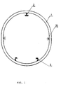
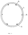
- Fig. 1 , 2 and 3 illustrate the basic ring ie. the frame of the transport system with tracks bonded in different positions.
- Fig. 4 illustrates the vertical support of the basic rings tube, in the shape of a single column.
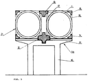
- Fig. 5 illustrates the partial cross-view of the vertical support of the basic rings of the annual tube, in the shape of a double column.
- Fig. 6 illustrates a somewhat changed cross-view of the vertical support of the basic rings annular tube in the first variety of implementation, from monolithic reinforced concrete.
- Fig. 7 illustrates the vertical support of the basic rings annular tube in the shape of the portal in the second variety of implementation.
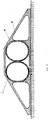
- Fig. 8 illustrates a cross-view of the vertical support of the basic rings annular tube with a ground level support structure in the third variety of implementation.
- Fig. 9 illustrates a cross-view of the vertical support of the basic rings annular tube with an underground support structure in the fourth variety of implementation.
- Fig.10 illustrates the perspective appearance of the assembled vertical, transverse and longitudinal supports of the annular grille tube from fig. 5.
- Fig.11 illustrates from the perspective appearence of the assembled vertical, transverse and longitudinal supports of the annular grille tube as well as the actual tube.
- FIG. 11 illustrates the basic frame ie. basic ring 1, 1a being the first element of the annular tube 21 of the system according to the invention.
- This basic ring 1, 1a as shown , is of the most favourable elliptical shape with the size ratio of the semi axis 1:1, 2 and with the cross-view of the ring square shaped from adequate material as prestressed concrete or profile steel supports etc. on the lower and upper side of the basic ring 1, 1a with the well known means of bonding tracks to the sleepers (not shown on the illustrations) bonded are the upper and/or lower tracks 2,3.
- upper and lower tracks 2,3 are of the well known shape and dimension and can be multipart tracks 2 as well as single tracks 3, together with other tracks of different shape.
- tracks 2,3 can be arranged differently.
- the most suitable arrangement with one multipart track 2, bonded to the upper side of the basic ring 1, 1a and with two single tracks 3 bonded spaced out on the lower side of the basic ring 1, 1a is shown in figure 1.
- Fig. 2 illustrates the solution with two single tracks 3 reciprocally disposed on the upper and lower side of the basic ring 1,1a
- Fig. 3 illustrates the solution with one multipart track 2 bonded to the upper and lower side of the basic ring 1.
- these vertical supports 4a are made as the well known reinforced concrete columns or vertical single columns 5 made from the welded steel profiles with upper supports 6 and lower supports 7. These vertical columns 5 are bonded with anchor plates 8 to its foundation.
- the traverse supports 6 and 7 are with the necessary bonding in the known way (not shown on the figures) disposed in the vertical axis lines 9 bonded to the basic rings 1 , where the railway, tracks and rails 2,3 are disposed .
- Vertical supports 4b are made of the same shape as the known reinforced concrete columns or double columns 10 made from welded steel profiles. These columns 10 are connected in the upper part by a horizontal frame beam 11, on which the central lower main longitudinal support 12 is disposed as well as the lower side longitudinal support 14. These main longitudinal supports 12 and the side longitudinal supports 14 together with the double columns 10 shape the supporting grille structure of the annular tube 21 connected by vertical bars 16 and horizontal bars 17 interconnected with the upper central main longitudinal support 13 and the side longitudinal supports 15 in the usual manner, on which in the usual manner the basic rings 1, are bonded, forming the annular tube 21, where the railway, tracks and rail 2,3 are disposed.
- Fig. 11 illustrates the vertical supports 4b of the basic rings 1 also made as double columns 10 with traverse frame beams 11 , on which the central main longitudinal lower support 12 and the lower side 14 are disposed.
- additional side supports 18 instead of the vertical and horizontal bars 16,17 additional side supports 18 have been disposed as well as connections 19 for connecting the basic rings 1 with the central upper main longitudinal support 13 as well as with the upper side longitudinal support 15.
- the annular tubes 21 are shaped, having the railway, tracks and rail 2,3.
- Fig. 6 illustrates the first structural variation to the construction of the vertical support 4c in the shape of the double column 10 made from monolithic reinforced concrete, on whose frame beams 11a are disposded monolithic interconnected basic rings 1a ( of the reinforced concrete structure), which form annular rib shaped tubes 21 with the railway, tracks and rails 2,3 disposed in it.
- Fig. 7 illustrates the second variety of implementation of the vertical support 4d in the shape of the portal column lob on whose frame beams 11b are hung with the known hanging elements 22 the described basic rings 1 forming the rib shaped annular tubes 21 with the disposed railway, tracks and rails 2,3.
- the known bond and support elements 23 are disposed.
- Fig. 8 illustrates the third variety of implementation of the suppport 4e in the shape of a ground level monolithic support 24 made as a reinforced concrete structure.
- Fig. 9 illustrates the fourth structural variety of implementation of support 4f in the shape of an underground profile 25, canal ie, tunel reinforced concrete or solid steel tubes 26 of the adequate profile, which have the same function as annular tube 21. These tubes 26 in profile 25 are dug into the ground under its level as is shown on Fig. 9 .
- the supports 4b are made as the structure described in the German patent DT 23 31 445 C3, where these vertical supports 4b are disposed with the possibility of adjusting in the travers direction of the position of the side longitudinal supports 12, 13, 14 and 15 which support the structure of annular tube 21, being bonded in that position with anchor bolts.
- These vertical supports 4b are made with frame beams 11 as side support elements together with the mentioned anchor bolt screws, whose upper surface according to one manner of realization is at 800 cm. minimum height above ground level, having at the same time the inner dimension of the ellipse axis basic rings 1 of 420 x 470 cm. with the thickness of the reinforced concrete wall of the basic ring 1 of 30 x 30 cm.
- annular tubes 21 with the pertaining basic rings 1, with longitudinal supports 12,13,14, 15 and 18 together with the grille bars 16,17 and the travers bonding 19, are disposed in accordance with the procedure and structure described in the German patent DT 22 16 484 C3, in seperate sections.
Landscapes
- Engineering & Computer Science (AREA)
- Mechanical Engineering (AREA)
- Architecture (AREA)
- Civil Engineering (AREA)
- Structural Engineering (AREA)
- Transportation (AREA)
- Railway Tracks (AREA)
- Platform Screen Doors And Railroad Systems (AREA)
- Tents Or Canopies (AREA)
- Chain Conveyers (AREA)
- Load-Engaging Elements For Cranes (AREA)
- Fittings On The Vehicle Exterior For Carrying Loads, And Devices For Holding Or Mounting Articles (AREA)
- Non-Mechanical Conveyors (AREA)
Claims (11)
- Le système de transport où des séries de chassis annulaires (1, 1a) sont interconnectées pour former une tube annulaire (21) dans laquelle est placé au moins une paire de supports (2, 3, 20) à fin de permettre le mouvement de légères véhicules avec les cabines de voyageurs, avec cela ses supports mentionnés (2, 3, 20) comprennent des rails latéraux de support (20), caractérisés par ce que ils contiennent en supplément des guides des supports inférieur (3) et supérieur (2) disposés sur les côtés opposées de chassis annulaires (1, 1a) dans le plan vertical pour que la véhicule puisse s'appuyer sur le rail inférieur (3) et en même temps être suspendue au rail supérieur (2) des guide de support (2, 3) et aussi par ce que les chassis annulaires (1, 1a) de préférance en forme elliptique, interconnectés par les poutres longitudinales (12, 13, 14, 15, 18, 19) séparement des guides mentionnés supérieur et inférieur (2) (3) et les rails mentionnés latéraux (20) pour former la tube, dont on a déjà parlé (21), et avec cela les tube annulaires (21) sont placées au-dessus de la terre, au niveau de la terre ou bien sous la terre.
- Le système de transport, conformément au p. 1 se caractérisant par ce que les chassis annulaires (1, 1a) de la côte supérieure sont fixés aux ras composés (2) et de la côté inférieurs sont fixés aux rails isolés.
- Le système de transport, conformément au p.1 se caractérisant par ce que les chassis annulaires (1, 1a) des ses côtés supérieure et inférieure sont fixés aux deux rails isolés et éspacés.
- Le système de transport, conformément au p.1 se caractérisant par ce que les chassis annulaires (1, 1a) de ses côtés inférieure et supérieure sont fixés à un rail compose.
- Le système de transport conformément au p.1-4 se caractérisant par ce que sur les supports verticaux (4a), fabriqués en forme des colonnes (5) isolées, faites le plus préférablement en béton armé ou bien le profilé en acier soudé avec les supports supérieurs transversaux (6) et les supports inférieurs transversaux (7) sont fixés les chassis annulaires (1), sur la même ligne axiale (9); faisant les tubes annulaires (21) avec la voie ferrée - rail et guide (2,3) - à l'intérieure.
- Le système de transport conformément au p.1-5 se caractérisant par ce que sur les supports verticaux (4b), faits comme les doubles colonnes (10), fabriqués le plus préférablement en béton armé, connectés sur la côté supérieur par la poutre horizontale (11) avec les supports centraux longitudinaux (12) et les supports latéraux longitudinaux (14), interconnectés par les barres verticales (16), avec lesquelles sont liés les supports centraux longitudinaux (13), sont fixés les chassis annulaires (1), formant la structure de support grillée des tubes annulaires.
- Le système de transport conformément au p.1-6 se caractérisant par ce que sur les barres horizontales (11) des doubles colonnes avec les centraux supports longitudinaux (12) et les supports latéraux longitudinaux (14) y placés, sont fixés les chassis annulaires (1) à l'aide des joints transversaux (19), interconnectés par les supports latéraux longitudinaux (18) et à l'aide des joints transversaux (19) ils ont fixés aux principaux supports centraux transversaux (13) et aux supports supérieurs latéraux transversaux (15) pour former la structure du présent systéme de transport.
- Le système de transport conformément au p.1-7 se caractérisant par ce que sur les supports verticaux (4c), faits en forme de double colonne coulée en masse (10a) le plus préférablement en béton armé, connectées par les poutres (11a), sont placé les chassis annulaires (1a).
- Le système de transport conformément au p.1-8 se caractérisant par ce que sur les supports verticaux (4d), fabriqués en forme des colonnes de portail (10b), le plus préférablement en béton armé ou bien en acier profilé soudé, connectée par les poutres (11b), sont placé les éléments suspendus (22) pour la suspension des chassis annulaires (1), fixés sur les deux côtés des colonnes (10b) avec les tubes annulaires.
- Le système de transport conformément au p.1-9 et la toisième variante de la réalisation se caractérisant par ce que dans les supports (4e), fabriqués le plus préférablement en béton armé coulé en masse les supports en forme de boite (24), les chassis annulaires (1) sont placés au niveau de la terre l'un après l'autre.
- Le système de transport conformément au p.1-4 se caractérisant par ce que dans les supports, fabriqués en forme des canaux souterrains (25) sont placées les tubes (26) des tubes annulaires (21) avec les chassis annulaires (1).
Applications Claiming Priority (2)
| Application Number | Priority Date | Filing Date | Title |
|---|---|---|---|
| YU1434/90 | 1990-07-23 | ||
| YU143490A YU47775B (sr) | 1990-07-23 | 1990-07-23 | Transportni sistem sa najmanje dve oslone tačke raspoređene na suprotnim stranama međusobno povezanih prstenastih okvira |
Publications (2)
| Publication Number | Publication Date |
|---|---|
| EP0468099A1 EP0468099A1 (fr) | 1992-01-29 |
| EP0468099B1 true EP0468099B1 (fr) | 1997-12-03 |
Family
ID=25554152
Family Applications (1)
| Application Number | Title | Priority Date | Filing Date |
|---|---|---|---|
| EP90125495A Expired - Lifetime EP0468099B1 (fr) | 1990-07-23 | 1990-12-27 | Système de transport avec au moins deux points d'appui arrangés aux cÔtés opposés des cadres annulaires interconnectés |
Country Status (7)
| Country | Link |
|---|---|
| US (1) | US5275111A (fr) |
| EP (1) | EP0468099B1 (fr) |
| JP (1) | JPH04133851A (fr) |
| AT (1) | ATE160735T1 (fr) |
| CA (1) | CA2035189A1 (fr) |
| DE (1) | DE69031775D1 (fr) |
| YU (1) | YU47775B (fr) |
Families Citing this family (18)
| Publication number | Priority date | Publication date | Assignee | Title |
|---|---|---|---|---|
| US6047645A (en) * | 1998-06-26 | 2000-04-11 | Setpoint Engineered Systems, Inc. | Truss track assembly and side mount roller coaster vehicle |
| US20020179419A1 (en) * | 1999-12-23 | 2002-12-05 | Tomlinson Andrew David | Enclosure system for conveyors |
| US6564721B2 (en) * | 2001-03-26 | 2003-05-20 | Robert L. Stiles | Rail transport system |
| CA2540690C (fr) * | 2003-09-29 | 2013-08-27 | Tubular Rail, Inc. | Systeme de transport |
| US20050284040A1 (en) * | 2004-06-03 | 2005-12-29 | Nippon Light Metal Company, Ltd. | Pedestal unit, raised floor skeleton structure, method of installing pedestal unit, and method of producing pedestal frame |
| JP4583394B2 (ja) * | 2006-03-03 | 2010-11-17 | 韓国ガス公社 | 足場装置およびそれを用いた断熱システムの設置方法 |
| CN100519288C (zh) * | 2007-08-25 | 2009-07-29 | 李荣生 | 管道物流运输装置 |
| US20100089275A1 (en) * | 2008-10-09 | 2010-04-15 | Darryl Lane | Mass transit system |
| US20140000473A1 (en) * | 2010-02-02 | 2014-01-02 | Supersonic Tubevehicle Llc | Transportation system and vehicle for supersonic transport |
| CN101992782A (zh) * | 2010-12-02 | 2011-03-30 | 张婧 | 城市无人驾驶电动有轨出租车交通系统 |
| CN102602400A (zh) * | 2012-03-19 | 2012-07-25 | 杜顺峰 | 一种电路控制磁力吸引的环形管道风力列车运行系统 |
| CN102708681B (zh) * | 2012-06-14 | 2014-01-22 | 吴新赞 | 一种城市智能交通运输系统及其运行方法 |
| CN105253150A (zh) * | 2014-07-16 | 2016-01-20 | 征先管联运输科技研究院(北京)有限公司 | 管道交通系统用运输管道 |
| MX2019007473A (es) * | 2016-12-22 | 2019-12-05 | Etran Inc | Sistema de transporte elevado. |
| CN114423665B (zh) * | 2019-09-18 | 2024-09-27 | 塔塔钢铁荷兰科技有限责任公司 | 用于抽真空管运输系统的管部段 |
| CN111648170A (zh) * | 2020-04-22 | 2020-09-11 | 杨鸿苍 | 一种未来都市轨道系统 |
| AU2022346281A1 (en) * | 2021-09-20 | 2024-04-04 | INDIAN INSTITUTE OF TECHNOLOGY MADRAS (IIT Madras) | Vacuum transportation system |
| US20250327251A1 (en) * | 2023-01-25 | 2025-10-23 | Robert DeDomenico | Switching system, and containerized parcel utility system comprising same |
Family Cites Families (17)
| Publication number | Priority date | Publication date | Assignee | Title |
|---|---|---|---|---|
| US373605A (en) * | 1887-11-22 | Elevated railway | ||
| US424168A (en) * | 1890-03-25 | Railway | ||
| US549936A (en) * | 1895-11-19 | Car for pneumatic railways | ||
| BE375647A (fr) * | ||||
| US2023906A (en) * | 1931-08-03 | 1935-12-10 | Joseph B Strauss | Air tram system of transportation |
| US2469432A (en) * | 1944-07-24 | 1949-05-10 | Cox Walter Cecil | Superspeed elevated railway |
| US3006288A (en) * | 1952-09-16 | 1961-10-31 | Brown Owen | System for high-speed transport |
| FR1347091A (fr) * | 1962-10-31 | 1963-12-27 | Entpr S Boussiron Soc D | Aménagements de la superstructure d'un chemin de fer suspendu |
| DE2159340A1 (de) * | 1971-11-30 | 1973-06-14 | Georg Hubmann | Rohrfoermige trasse fuer gleisgebundene fahrzeuge |
| DE2216484B2 (de) * | 1972-04-06 | 1975-03-13 | Dyckerhoff & Widmann Ag, 8000 Muenchen | Verfahren zum Herstellen einer Fahrbahn aus Stahl- oder Spannbeton sowie nach diesem Verfahren hergestellte Fahrbahn |
| US4503778A (en) * | 1982-01-22 | 1985-03-12 | Wilson Fillmore G | Transportation system |
| DE3279176D1 (en) * | 1982-08-30 | 1988-12-08 | Kosuke Matsukata | High speed underground transport system |
| US4703697A (en) * | 1984-04-19 | 1987-11-03 | Bell George S | Transportation system |
| DE3503504A1 (de) * | 1985-02-02 | 1986-08-07 | Peter 5090 Leverkusen Kibele | Kabinenbahn fuer den personentransport |
| DE3612848A1 (de) * | 1986-04-16 | 1987-10-22 | Klaue Hermann | Magnetbahn-transportanlage fuer personen-kabinen und gueterbehaelter |
| DE3612847A1 (de) * | 1986-04-16 | 1987-10-22 | Klaue Hermann | Magnetbahn-transportanlage fuer personen-kabinen und gueterbehaelter |
| DE3640779A1 (de) * | 1986-11-28 | 1987-10-08 | Fidelius Futterknecht | Umweltgerechtes, energiesparendes hochgeschwindigkeits verkehrsanlage system |
-
1990
- 1990-07-23 YU YU143490A patent/YU47775B/sh unknown
- 1990-12-27 EP EP90125495A patent/EP0468099B1/fr not_active Expired - Lifetime
- 1990-12-27 AT AT90125495T patent/ATE160735T1/de not_active IP Right Cessation
- 1990-12-27 JP JP2414835A patent/JPH04133851A/ja active Pending
- 1990-12-27 DE DE69031775T patent/DE69031775D1/de not_active Expired - Lifetime
-
1991
- 1991-01-29 CA CA002035189A patent/CA2035189A1/fr not_active Abandoned
- 1991-03-21 US US07/672,958 patent/US5275111A/en not_active Expired - Fee Related
Also Published As
| Publication number | Publication date |
|---|---|
| JPH04133851A (ja) | 1992-05-07 |
| EP0468099A1 (fr) | 1992-01-29 |
| US5275111A (en) | 1994-01-04 |
| CA2035189A1 (fr) | 1992-01-24 |
| YU47775B (sr) | 1996-01-09 |
| DE69031775D1 (de) | 1998-01-15 |
| YU143490A (sh) | 1994-05-10 |
| ATE160735T1 (de) | 1997-12-15 |
Similar Documents
| Publication | Publication Date | Title |
|---|---|---|
| EP0468099B1 (fr) | Système de transport avec au moins deux points d'appui arrangés aux cÔtés opposés des cadres annulaires interconnectés | |
| US3890904A (en) | Railway system | |
| US4690064A (en) | Side-mounted monorail transportation system | |
| US8375865B2 (en) | Overhead suspended personal transportation and freight delivery surface transportation system | |
| DE69932847T2 (de) | Einschienenbahnsystem | |
| FI89886B (fi) | Magnetkraftsystem foer friktionsfattig transport av laster | |
| EP2274191B1 (fr) | Voie surélevée pour un véhicule à système de propulsion pneumatique | |
| EP0086788B1 (fr) | Ameliorations relatives a des moyens de transport | |
| US3368496A (en) | Transportation system | |
| US8371226B2 (en) | Air cushion or wheeled overhead guideway system | |
| US6925941B2 (en) | Elevated train | |
| EP3558780B1 (fr) | Système de transport surélevé | |
| US3710727A (en) | Air beam way and switching system | |
| US3630153A (en) | Vehicle-enclosed railway transportation system | |
| US4233908A (en) | Construction of reactor-driven articulated trains with elevated tracks | |
| WO1995026896A2 (fr) | Systeme de transport de vehicule sur coussin d'air | |
| CN115961510B (zh) | 一种复合轨道车站线路及车站 | |
| US3882786A (en) | Transit system | |
| US3942450A (en) | Overhead transportation system | |
| CN110748215A (zh) | 悬挂列车出入库系统、悬挂列车移载装置和悬挂式车库 | |
| CN211422003U (zh) | 悬挂列车出入库系统、悬挂列车移载装置和悬挂式车库 | |
| US3811616A (en) | High speed train track | |
| JPH02124358A (ja) | 都市鉄道型の乗客集団輸送装置 | |
| RU2205761C1 (ru) | Модульная транспортная система и способ ее эксплуатации | |
| JPS59145801A (ja) | 輸送設備における案内路の構造 |
Legal Events
| Date | Code | Title | Description |
|---|---|---|---|
| PUAI | Public reference made under article 153(3) epc to a published international application that has entered the european phase |
Free format text: ORIGINAL CODE: 0009012 |
|
| 17P | Request for examination filed |
Effective date: 19901228 |
|
| AK | Designated contracting states |
Kind code of ref document: A1 Designated state(s): AT BE CH DE DK ES FR GB IT LI NL SE |
|
| 17Q | First examination report despatched |
Effective date: 19931027 |
|
| GRAG | Despatch of communication of intention to grant |
Free format text: ORIGINAL CODE: EPIDOS AGRA |
|
| GRAG | Despatch of communication of intention to grant |
Free format text: ORIGINAL CODE: EPIDOS AGRA |
|
| GRAH | Despatch of communication of intention to grant a patent |
Free format text: ORIGINAL CODE: EPIDOS IGRA |
|
| GRAH | Despatch of communication of intention to grant a patent |
Free format text: ORIGINAL CODE: EPIDOS IGRA |
|
| RAP1 | Party data changed (applicant data changed or rights of an application transferred) |
Owner name: SAVICEVIC, MILORAD |
|
| GRAA | (expected) grant |
Free format text: ORIGINAL CODE: 0009210 |
|
| RAP1 | Party data changed (applicant data changed or rights of an application transferred) |
Owner name: SAVICEVIC, MILORAD |
|
| AK | Designated contracting states |
Kind code of ref document: B1 Designated state(s): AT BE CH DE DK ES FR GB IT LI NL SE |
|
| PG25 | Lapsed in a contracting state [announced via postgrant information from national office to epo] |
Ref country code: IT Free format text: LAPSE BECAUSE OF FAILURE TO SUBMIT A TRANSLATION OF THE DESCRIPTION OR TO PAY THE FEE WITHIN THE PRE;WARNING: LAPSES OF ITALIAN PATENTS WITH EFFECTIVE DATE BEFORE 2007 MAY HAVE OCCURRED AT ANY TIME BEFORE 2007. THE CORRECT EFFECTIVE DATE MAY BE DIFFERENT FROM THE ONE RECORDED.SCRIBED TIME-LIMIT Effective date: 19971203 Ref country code: ES Free format text: THE PATENT HAS BEEN ANNULLED BY A DECISION OF A NATIONAL AUTHORITY Effective date: 19971203 Ref country code: DK Free format text: LAPSE BECAUSE OF NON-PAYMENT OF DUE FEES Effective date: 19971203 Ref country code: FR Free format text: LAPSE BECAUSE OF FAILURE TO SUBMIT A TRANSLATION OF THE DESCRIPTION OR TO PAY THE FEE WITHIN THE PRESCRIBED TIME-LIMIT Effective date: 19971203 Ref country code: NL Free format text: LAPSE BECAUSE OF FAILURE TO SUBMIT A TRANSLATION OF THE DESCRIPTION OR TO PAY THE FEE WITHIN THE PRESCRIBED TIME-LIMIT Effective date: 19971203 Ref country code: BE Free format text: LAPSE BECAUSE OF FAILURE TO SUBMIT A TRANSLATION OF THE DESCRIPTION OR TO PAY THE FEE WITHIN THE PRESCRIBED TIME-LIMIT Effective date: 19971203 Ref country code: AT Free format text: LAPSE BECAUSE OF FAILURE TO SUBMIT A TRANSLATION OF THE DESCRIPTION OR TO PAY THE FEE WITHIN THE PRESCRIBED TIME-LIMIT Effective date: 19971203 |
|
| REF | Corresponds to: |
Ref document number: 160735 Country of ref document: AT Date of ref document: 19971215 Kind code of ref document: T |
|
| REG | Reference to a national code |
Ref country code: CH Ref legal event code: EP |
|
| REF | Corresponds to: |
Ref document number: 69031775 Country of ref document: DE Date of ref document: 19980115 |
|
| PG25 | Lapsed in a contracting state [announced via postgrant information from national office to epo] |
Ref country code: GB Free format text: LAPSE BECAUSE OF NON-PAYMENT OF DUE FEES Effective date: 19980303 Ref country code: SE Free format text: LAPSE BECAUSE OF FAILURE TO SUBMIT A TRANSLATION OF THE DESCRIPTION OR TO PAY THE FEE WITHIN THE PRESCRIBED TIME-LIMIT Effective date: 19980303 |
|
| PG25 | Lapsed in a contracting state [announced via postgrant information from national office to epo] |
Ref country code: DE Free format text: LAPSE BECAUSE OF FAILURE TO SUBMIT A TRANSLATION OF THE DESCRIPTION OR TO PAY THE FEE WITHIN THE PRESCRIBED TIME-LIMIT Effective date: 19980304 |
|
| PGFP | Annual fee paid to national office [announced via postgrant information from national office to epo] |
Ref country code: CH Payment date: 19980403 Year of fee payment: 8 |
|
| EN | Fr: translation not filed | ||
| NLV1 | Nl: lapsed or annulled due to failure to fulfill the requirements of art. 29p and 29m of the patents act | ||
| REG | Reference to a national code |
Ref country code: CH Ref legal event code: PL Ref country code: CH Ref legal event code: AEN Free format text: DIE LOESCHUNG VOM 31.12.1997 ERFOLGTE IRRTUEMLICH, DAS PATENT WURDE REAKTIVIERT. |
|
| PLBE | No opposition filed within time limit |
Free format text: ORIGINAL CODE: 0009261 |
|
| STAA | Information on the status of an ep patent application or granted ep patent |
Free format text: STATUS: NO OPPOSITION FILED WITHIN TIME LIMIT |
|
| GBPC | Gb: european patent ceased through non-payment of renewal fee |
Effective date: 19980303 |
|
| 26N | No opposition filed | ||
| PG25 | Lapsed in a contracting state [announced via postgrant information from national office to epo] |
Ref country code: CH Free format text: LAPSE BECAUSE OF NON-PAYMENT OF DUE FEES Effective date: 19981231 Ref country code: LI Free format text: LAPSE BECAUSE OF NON-PAYMENT OF DUE FEES Effective date: 19981231 |
|
| REG | Reference to a national code |
Ref country code: CH Ref legal event code: PL |