EP0468148A2 - Verfahren und Apparat zur Herstellung von plattenförmigen und mit Noppen versehenen Elementen, insbesondere Bodenbeläge und derart hergestellte Elemente - Google Patents
Verfahren und Apparat zur Herstellung von plattenförmigen und mit Noppen versehenen Elementen, insbesondere Bodenbeläge und derart hergestellte Elemente Download PDFInfo
- Publication number
- EP0468148A2 EP0468148A2 EP91107185A EP91107185A EP0468148A2 EP 0468148 A2 EP0468148 A2 EP 0468148A2 EP 91107185 A EP91107185 A EP 91107185A EP 91107185 A EP91107185 A EP 91107185A EP 0468148 A2 EP0468148 A2 EP 0468148A2
- Authority
- EP
- European Patent Office
- Prior art keywords
- plugs
- elastomeric material
- plate
- support slab
- slab
- Prior art date
- Legal status (The legal status is an assumption and is not a legal conclusion. Google has not performed a legal analysis and makes no representation as to the accuracy of the status listed.)
- Pending
Links
- 238000000034 method Methods 0.000 title claims description 30
- 238000000465 moulding Methods 0.000 claims abstract description 72
- 239000013536 elastomeric material Substances 0.000 claims abstract description 67
- 239000000463 material Substances 0.000 claims abstract description 18
- 238000004519 manufacturing process Methods 0.000 claims abstract description 12
- 238000005452 bending Methods 0.000 claims description 11
- 230000001747 exhibiting effect Effects 0.000 claims description 11
- 238000004073 vulcanization Methods 0.000 claims description 5
- 238000004891 communication Methods 0.000 claims description 4
- 238000002347 injection Methods 0.000 claims description 3
- 239000007924 injection Substances 0.000 claims description 3
- 238000006073 displacement reaction Methods 0.000 claims description 2
- 230000008878 coupling Effects 0.000 claims 1
- 238000010168 coupling process Methods 0.000 claims 1
- 238000005859 coupling reaction Methods 0.000 claims 1
- 238000001746 injection moulding Methods 0.000 abstract 1
- 239000000047 product Substances 0.000 description 7
- 238000005520 cutting process Methods 0.000 description 5
- 239000002699 waste material Substances 0.000 description 4
- 238000005299 abrasion Methods 0.000 description 3
- 230000015572 biosynthetic process Effects 0.000 description 3
- 230000006835 compression Effects 0.000 description 2
- 238000007906 compression Methods 0.000 description 2
- 230000000694 effects Effects 0.000 description 2
- 238000010438 heat treatment Methods 0.000 description 2
- 230000000284 resting effect Effects 0.000 description 2
- 239000011265 semifinished product Substances 0.000 description 2
- 229910000831 Steel Inorganic materials 0.000 description 1
- 239000003086 colorant Substances 0.000 description 1
- 230000037228 dieting effect Effects 0.000 description 1
- 230000002349 favourable effect Effects 0.000 description 1
- 238000005304 joining Methods 0.000 description 1
- 238000012986 modification Methods 0.000 description 1
- 230000004048 modification Effects 0.000 description 1
- 238000000926 separation method Methods 0.000 description 1
- 239000010959 steel Substances 0.000 description 1
Images


Classifications
-
- B—PERFORMING OPERATIONS; TRANSPORTING
- B29—WORKING OF PLASTICS; WORKING OF SUBSTANCES IN A PLASTIC STATE IN GENERAL
- B29C—SHAPING OR JOINING OF PLASTICS; SHAPING OF MATERIAL IN A PLASTIC STATE, NOT OTHERWISE PROVIDED FOR; AFTER-TREATMENT OF THE SHAPED PRODUCTS, e.g. REPAIRING
- B29C43/00—Compression moulding, i.e. applying external pressure to flow the moulding material; Apparatus therefor
- B29C43/02—Compression moulding, i.e. applying external pressure to flow the moulding material; Apparatus therefor of articles of definite length, i.e. discrete articles
- B29C43/021—Compression moulding, i.e. applying external pressure to flow the moulding material; Apparatus therefor of articles of definite length, i.e. discrete articles characterised by the shape of the surface
-
- B—PERFORMING OPERATIONS; TRANSPORTING
- B29—WORKING OF PLASTICS; WORKING OF SUBSTANCES IN A PLASTIC STATE IN GENERAL
- B29C—SHAPING OR JOINING OF PLASTICS; SHAPING OF MATERIAL IN A PLASTIC STATE, NOT OTHERWISE PROVIDED FOR; AFTER-TREATMENT OF THE SHAPED PRODUCTS, e.g. REPAIRING
- B29C43/00—Compression moulding, i.e. applying external pressure to flow the moulding material; Apparatus therefor
- B29C43/02—Compression moulding, i.e. applying external pressure to flow the moulding material; Apparatus therefor of articles of definite length, i.e. discrete articles
- B29C43/18—Compression moulding, i.e. applying external pressure to flow the moulding material; Apparatus therefor of articles of definite length, i.e. discrete articles incorporating preformed parts or layers, e.g. compression moulding around inserts or for coating articles
-
- B—PERFORMING OPERATIONS; TRANSPORTING
- B29—WORKING OF PLASTICS; WORKING OF SUBSTANCES IN A PLASTIC STATE IN GENERAL
- B29C—SHAPING OR JOINING OF PLASTICS; SHAPING OF MATERIAL IN A PLASTIC STATE, NOT OTHERWISE PROVIDED FOR; AFTER-TREATMENT OF THE SHAPED PRODUCTS, e.g. REPAIRING
- B29C45/00—Injection moulding, i.e. forcing the required volume of moulding material through a nozzle into a closed mould; Apparatus therefor
- B29C45/0053—Injection moulding, i.e. forcing the required volume of moulding material through a nozzle into a closed mould; Apparatus therefor combined with a final operation, e.g. shaping
- B29C45/006—Joining parts moulded in separate cavities
-
- B—PERFORMING OPERATIONS; TRANSPORTING
- B29—WORKING OF PLASTICS; WORKING OF SUBSTANCES IN A PLASTIC STATE IN GENERAL
- B29C—SHAPING OR JOINING OF PLASTICS; SHAPING OF MATERIAL IN A PLASTIC STATE, NOT OTHERWISE PROVIDED FOR; AFTER-TREATMENT OF THE SHAPED PRODUCTS, e.g. REPAIRING
- B29C45/00—Injection moulding, i.e. forcing the required volume of moulding material through a nozzle into a closed mould; Apparatus therefor
- B29C45/02—Transfer moulding, i.e. transferring the required volume of moulding material by a plunger from a "shot" cavity into a mould cavity
-
- B—PERFORMING OPERATIONS; TRANSPORTING
- B29—WORKING OF PLASTICS; WORKING OF SUBSTANCES IN A PLASTIC STATE IN GENERAL
- B29C—SHAPING OR JOINING OF PLASTICS; SHAPING OF MATERIAL IN A PLASTIC STATE, NOT OTHERWISE PROVIDED FOR; AFTER-TREATMENT OF THE SHAPED PRODUCTS, e.g. REPAIRING
- B29C69/00—Combinations of shaping techniques not provided for in a single one of main groups B29C39/00 - B29C67/00, e.g. associations of moulding and joining techniques; Apparatus therefore
- B29C69/004—Combinations of shaping techniques not provided for in a single one of main groups B29C39/00 - B29C67/00, e.g. associations of moulding and joining techniques; Apparatus therefore making articles by joining parts moulded in separate cavities, said parts being in said separate cavities during said joining
-
- B—PERFORMING OPERATIONS; TRANSPORTING
- B29—WORKING OF PLASTICS; WORKING OF SUBSTANCES IN A PLASTIC STATE IN GENERAL
- B29C—SHAPING OR JOINING OF PLASTICS; SHAPING OF MATERIAL IN A PLASTIC STATE, NOT OTHERWISE PROVIDED FOR; AFTER-TREATMENT OF THE SHAPED PRODUCTS, e.g. REPAIRING
- B29C70/00—Shaping composites, i.e. plastics material comprising reinforcements, fillers or preformed parts, e.g. inserts
- B29C70/68—Shaping composites, i.e. plastics material comprising reinforcements, fillers or preformed parts, e.g. inserts by incorporating or moulding on preformed parts, e.g. inserts or layers, e.g. foam blocks
- B29C70/74—Moulding material on a relatively small portion of the preformed part, e.g. outsert moulding
-
- B—PERFORMING OPERATIONS; TRANSPORTING
- B29—WORKING OF PLASTICS; WORKING OF SUBSTANCES IN A PLASTIC STATE IN GENERAL
- B29C—SHAPING OR JOINING OF PLASTICS; SHAPING OF MATERIAL IN A PLASTIC STATE, NOT OTHERWISE PROVIDED FOR; AFTER-TREATMENT OF THE SHAPED PRODUCTS, e.g. REPAIRING
- B29C43/00—Compression moulding, i.e. applying external pressure to flow the moulding material; Apparatus therefor
- B29C43/02—Compression moulding, i.e. applying external pressure to flow the moulding material; Apparatus therefor of articles of definite length, i.e. discrete articles
- B29C43/021—Compression moulding, i.e. applying external pressure to flow the moulding material; Apparatus therefor of articles of definite length, i.e. discrete articles characterised by the shape of the surface
- B29C2043/023—Compression moulding, i.e. applying external pressure to flow the moulding material; Apparatus therefor of articles of definite length, i.e. discrete articles characterised by the shape of the surface having a plurality of grooves
-
- B—PERFORMING OPERATIONS; TRANSPORTING
- B29—WORKING OF PLASTICS; WORKING OF SUBSTANCES IN A PLASTIC STATE IN GENERAL
- B29C—SHAPING OR JOINING OF PLASTICS; SHAPING OF MATERIAL IN A PLASTIC STATE, NOT OTHERWISE PROVIDED FOR; AFTER-TREATMENT OF THE SHAPED PRODUCTS, e.g. REPAIRING
- B29C43/00—Compression moulding, i.e. applying external pressure to flow the moulding material; Apparatus therefor
- B29C43/02—Compression moulding, i.e. applying external pressure to flow the moulding material; Apparatus therefor of articles of definite length, i.e. discrete articles
- B29C43/021—Compression moulding, i.e. applying external pressure to flow the moulding material; Apparatus therefor of articles of definite length, i.e. discrete articles characterised by the shape of the surface
- B29C2043/026—Compression moulding, i.e. applying external pressure to flow the moulding material; Apparatus therefor of articles of definite length, i.e. discrete articles characterised by the shape of the surface having functional projections, e.g. fasteners
Definitions
- the present invention relates to a process and an apparatus to make plugged plate-like elements, in particular for covering pavings, as well as the product obtained by the above process and apparatus.
- the apparatus in accordance with the invention is of the type comprising:
- the obtained plugged plate-like element is of the type comprising:
- the present invention is particularly concerned with the production of plate-like elements for covering pavings of the type made from two different elastomeric materials.
- the use of two different elastomeric materials is made necessary when the exposed surface is wished to exhibit a different quality than the support slab.
- the first elastomeric material on the exposed side thereof, that is the one exhibiting the plugs, will be completely coated with the second elastomeric material.
- Another drawback consists in the great waste of material, as a result of the scraps that are obtained from the plug cutting or the mechanical- abrasion operation.
- a further drawback is represented by the fact that the first elastomeric material forming the plugs inevitably covers the whole plate-like element on the base side thereof which will rest on the paving to be covered.
- the main object of the present invention is substantially to solve all problems of the known art by a process that, without involving any cutting or abrasion action which results in the production of scraps or waste material, enables a plugged plate-like element to be achieved by the use of two different elastomeric materials in which one elastomeric material will exclusively form the plugs whereas the second elastomeric material will form the support slab to which the plugs are applied.
- the obtained plugged plate-like element will mainly consist of an inexpensive elastomeric material and will only have a low percent of valuable elastomeric material.
- Another important object of the invention is to manufacture the plate-like elements in a simple, precise and reliable manner.
- Still another object of the invention is to provide a process enabling the produced plugs to have any desired conformation.
- this process is put into practice by an apparatus to make plugged plate-like elements, in particular for covering pavings, characterized in that it comprises a dispensing plate to be operatively engaged to the moulding die and exhibiting a plurality of transferring holes putting said forming recesses in communication with a collection chamber formed in the dispensing plate, on the opposite side from the moulding die; a piston to be slidably engaged into the reception chamber and movable towards the dispensing plate to transfer a first elastomeric material contained in the collection chamber to the forming recesses, said support slab being made separately from the plugs and being coupled to the plugs as a result of the mutual moving close of the moulding die and the pressure element.
- a plugged plate-like element which is characterized in that said plugs are formed from a first elastomeric material and the support slab from a second elastomeric material having features different from those of the first elastomeric material.
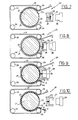
- an apparatus to make plugged plate-like elements to be particularly used for covering pavings has been generally identified by reference numeral 1.
- Apparatus 1 is adapted to produce a plugged plate-like element 2 of the type comprising a support slab 3 of elastomeric material exhibiting a base side 3a designed to be laid in contact with a surface 4 to be covered and an upper side 3b on which a plurality of plugs 5 of elastomeric material preferably having a flattened substantially cylindrical configuration is homogeneously distributed.
- the plugged plate-like element 1 is manufactured in accordance with a process providing the following steps:
- apparatus 1 comprises a moulding die 6 substantially extending according to a horizontal plane and vertically movable towards a pressure element 7, extending under the moulding die, parallelly thereto.
- the moulding die 6 has a plurality of forming recesses 8 at the lower part thereof, which are homogeneously distributed over a predetermined area and each of them being arranged to house one of the plugs 5 to be applied to the plugged plate-like element 2, as best clarified in the following.
- the pressure element 7 is in turn arranged to engage, between shoulder kerbs 9 provided thereon, the support slab 3 designed to receive the plugs 4.
- apparatus 1 further comprises a dispensing plate 10 extending parallelly to the moulding die 6 and adapted to be operatively engaged thereto.
- the dispensing plate 10 has a substantially flat upper surface 10a to be coupled with the lower surface 6a of the moulding die 6, so as to obtain a tight seal with the edges of the forming recesses 8.
- the dispensing plate 10 is also provided with a plurality of transferring holes or passage channels 11, each of which brings one of the forming recesses 8 into communication with a collection chamber 12 formed in the dispensing plate, on the opposite side from the moulding die 6.
- a piston 13 Associated with the dispensing plate 10 is a piston 13, which also has a substantially plate-like configuration and extends between the dispensing plate and the pressure element 7, parallelly thereto.
- the piston 13 is adapted to be slidably engaged to the collection chamber 12 for purposes to be clarified in the following.
- piston 13 is preferably provided to act by contact on the kerbs 9 so as to define, together with the pressure element 7, a moulding chamber 14 into which an injection nozzle 15 associated with the pressure element itself opens, for the purposes to be illustrated later.
- the dispensing plate 10 and piston 13 are provided to be simultaneously movable in a substantially horizontal direction from an engagement position in which they are interposed between the moulding die 6 and the pressure element 7 (Figs. 1 and 2), and an idle position in which they are spaced apart sideways from the die 6 and the pressure element 7 to enable the die to move close to the pressure element itself (Figs. 3 and 4).
- the dispensing plate 10 and piston 13 are located in the use position, as viewed from Fig. 1.
- the dispensing plate 10 is operatively engaged to the moulding die 6 so that its upper surface 10a is in contact with the lower surface 6a of the moulding die.
- Piston 13 in turn, lies on the kerbs 9 provided on the pressure element 7.
- a predetermined amount of a first elastomeric material in a raw state denoted by 16 in Fig. 1, is disposed on piston 13 either manually by an operator or by automatic loading means.
- the moulding action thus produced on the first elastomeric material 16 gives therefore rise to the simultaneous formation of a plurality of plugs 5 homogeneously distributed over a predetermined area without involving the formation of burrs projecting from the plug contour, which plugs are designed to be applied to the support slab 3.
- the ratio between the maximum diameter of each of the forming recesses 8, denoted by “D” in Fig. 1, and the thickness of the dispensing plate 10 denoted by “S” should preferably have a value ranging between 2.5 and 5. More particularly, the thickness "S" of the dispensing plate 10 should be calculated based on the following formula: where:
- the production of plate-like elements of square plan configuration is provided, their side being of 500 mm, where the thickness of the support slab 3 is of 3 mm whereas that of the plugs 5 is 2 mm, the plugs 5 having a diameter of 25 mm.
- the thickness "S" of the dispensing plate 10 is provided to be of 7 mm.
- the dispensing plate 10 and moulding die 6 inevitably undergo bending microdeformations the value of which can be included, just as an indication, between 0.001 and 0.5 mm.
- microdeformations should not be suitably controlled, they could give rise to structure faults on the finished products, in the form of colour smudges or at all events burrs of the material constituting the plugs 5 that would extend to the support slab 3.
- each of the forming recesses 8 subtends an area susceptible of deformation on the dispensing plate 10, which area is defined by the section portion denoted by "T" in Fig. 1, the bending behaviour of which can be compared to that of a beam resting on two points represented by the opposite edges of the recess itself.
- each area susceptible of deformation "T" that can be detected in the section of the dispensing plate must have a bending stiffness substantially equal to the bending stiffness that can be found on the whole moulding die 6 in use.
- this effect is achieved by giving a thickness of 25 mm to the moulding die 6.
- the support slab 3 is produced in the moulding chamber 14 by injecting thereinto a second elastomeric material having different features than the first elastomeric material, through the nozzle 15.
- the manufacture of the support slab 3 takes place immediately after the moulding of the plugs 5, but can optionally be carried out also before or during this moulding step, the pressure element 7 and piston 13 being arranged in the conditions shown in Figs. 1 and 2.
- the support slab 3 has the predetermined and desired sizes by virtue of the indeformable character of the walls enclosing the injection space, as the thicknesses of the piston 13 and pressure element 7 drawn in Fig. 1 clearly show.
- the support slab 3 can also be manufactured separately and arranged so as to lie on the pressure element 7 for the application of the plugs 5.
- the piston 13 and dispensing plate 10 are first brought to the idle position so as to be located spaced apart from the moulding die 6, as shown in Fig. 3, after carrying out the relative moving away between the die and the pressure element.
- apparatus 1 will be disposed in a condition in which the moulding die 6 engages the plugs 5 within the respective forming recesses 8, at a raised position relative to the pressure element 7, whereas the pressure element 7 itself supports the support slab 3 resting thereon.
- the moulding die 6 and pressure element 7 are held in this condition as far as the vulcanization of the elastomeric materials forming the plugs 5 and support slab 3 has taken place.
- This vulcanization step is conventionally assisted by the action of heating means not shown as known per se, associated with the moulding die 6.
- the moulding die 6 When the vulcanisation step has been completed, the moulding die 6 will be raised again to enable the obtained plugged plate-like element 2 to be removed.
- the plate-like element thus obtained will have the particular quality of exhibiting plugs 5 made from a first elastomeric material applied to a support slab 3 formed from a second elastomeric material of quite different characteristics than the first elastomeric material.
- Figs. 6, 6a, 6b and 6c represent some embodiments of the plugged elements 2 that can be made by adopting processes in which the plugs and the slab are formed separately and the plugs are then joined to the slab, said embodiments being in particular obtainable with the process of the present invention.
- Fig. 6 Shown in Fig. 6 is an embodiment in which the plug 5 has a substantially frusto-conical configuration and is joined to the support slab 3 at substantially flat surfaces thereof.
- each plug 5 is preferably provided to have, in the middle, a small surface relief 5c which is buried in the elastomeric material of the support slab 3.
- the surface relief 5c advantageously ensures a steady positioning of the corresponding plug 5 in connection with transverse movements, both during the production of the plate-like element and during the use of the same.
- Fig. 6a Shown in Fig. 6a is a plug the sectional profile of which exhibits a convex upper surface 5a joined to the upper side 3b of the support slab 3 by means of curvilinear connecting portions 5b.
- Fig. 6a Still shown in Fig. 6a is the possibility of joining the plug 5 to the support slab at areas 5c thereof exhibiting a wrinkled surface extension.
- each plug 5 can also be joined to the support slab 3 at a surface relief 3c formed on the upper side 3b of the slab itself. As still viewed from said figure, the plug 5 can also be joined to the support slab 3 correspondingly to a surface recess 3d formed on the base side 3a of the slab itself.
- the plug is joined to the support slab 3 at a through hole 3e formed in the slab.
- Figs 7 to 10 show a second embodiment of the apparatus of the invention generally denoted by 20, seen during different steps of the operating cycle.
- the moulding die identified by 21 has a cylindrical configuration and the forming recesses 22 are distributed on its outer surface 21a.
- the moulding die 21 is operable in rotation according to a stepped movement about its own axis and is partly wrapped by the pressure element 23 now in the form of a ribbon preferably made of steel, guided on respective idler rollers 24 and dragged along by the rotatory motion imparted to the moulding die 21.
- apparatus 20 further comprises a dispensing plate 25 adapted to be operatively engaged to the outer cylindrical surface 21 a of the moulding die 21, at an area where the pressure element 23 is not present.
- the dispensing plate 25 is provided to be movable from an idle position in which it is slightly spaced apart from the moulding die 21 (Figs. 7 and 10) to an operating position in which it acts by contact on the cylindrical surface 21 a of the die itself, preferably along a generatrix of the latter.
- a plurality of transferring holes 26 (only one of which is shown in the accompanying drawings), each of them being arranged to bring one of the forming recesses 22 into communication with a collection chamber 27 formed in the dispensing plate 25, when the plate is in the work condition.
- the collection chamber 27 is designed to be slidably engaged by a piston 28 movable towards the dispensing plate 25.
- the support slab 3 previously produced or directly coming from the extruder mouth is provided to be continuously fed between the pressure element and the moulding die 21, set in rotation in a stepped mode.
- the dispensing plate 25 and piston 28 cooperate together so that, each time the die 21 stops rotating, the forming recesses 22 aligned in register with the dispensing plate are filled with elastomeric material.
- the plugs 5 thus obtained are matched with the support slab 3 at the engagement area between the pressure element 23 and the moulding die 21. Then the plugs 5 and the slab 3 will be vulcanized upon the action of heating means not shown as known per se, associated with the moulding die 6 over the whole time necessary for the obtained plugged plate-like element 2 to come out of apparatus 20, due to the rotation of the die 6.
- the first elastomeric material designed to form the plugs 5 is first disposed in the collection chamber 27. Under this situation the dispensing plate 25 is in the idle position and the piston 28 is spaced apart from the plate itself (Fig. 7).
- the present invention attains the intended purposes.
- the process and apparatus in reference in fact allow plate-like elements to be manufactured in a practical, precise and reliable manner and without waste of material in the form of scraps, in which plate-like elements the plugs 5 are made of an elastomeric material different as regards colour and/or physico-technical features, from the material forming the support slab 3.
- the more valuable elastomeric material that is the one that must exhibit a greater mechanical resistance to wear together with a high friction coefficient, will only form the plugs 5.
- the whole support slab 3 can be advantageously made from inexpensive elastomeric material, or at all events a material having a lower cost than the material used for the plugs 5.
- the concerned process and apparatus enable any desired configuration to be given to the plugs 5.
- the process and apparatus could be used to form the plugs and the slab with one and the same material, at different times and/or even simultaneously.
- the plate-like element could consist of plugs of several different colours, each of them being in turn different from the colour of the support slab 3.
Landscapes
- Engineering & Computer Science (AREA)
- Mechanical Engineering (AREA)
- Manufacturing & Machinery (AREA)
- Chemical & Material Sciences (AREA)
- Composite Materials (AREA)
- Moulds For Moulding Plastics Or The Like (AREA)
- Stringed Musical Instruments (AREA)
Applications Claiming Priority (2)
| Application Number | Priority Date | Filing Date | Title |
|---|---|---|---|
| IT20206A IT1240636B (it) | 1990-05-04 | 1990-05-04 | Procedimento ed apparecchiatura per la realizzazione di elementi piastriformi tassellati, particolarmente per rivestire pavimentazioni,ed elemento piastriforme tassellato ottenuto |
| IT2020690 | 1990-05-04 |
Publications (1)
| Publication Number | Publication Date |
|---|---|
| EP0468148A2 true EP0468148A2 (de) | 1992-01-29 |
Family
ID=11164758
Family Applications (1)
| Application Number | Title | Priority Date | Filing Date |
|---|---|---|---|
| EP91107185A Pending EP0468148A2 (de) | 1990-05-04 | 1991-05-03 | Verfahren und Apparat zur Herstellung von plattenförmigen und mit Noppen versehenen Elementen, insbesondere Bodenbeläge und derart hergestellte Elemente |
Country Status (2)
| Country | Link |
|---|---|
| EP (1) | EP0468148A2 (de) |
| IT (1) | IT1240636B (de) |
Cited By (3)
| Publication number | Priority date | Publication date | Assignee | Title |
|---|---|---|---|---|
| EP0733463A3 (de) * | 1995-03-10 | 1996-10-09 | Sumitomo Wiring Systems, Ltd. | Verfahren zur Herstellung eines mehrteiligen Giessharzobjektes, Metallwerkzeug sowie hergestelltes mehrteiliges Giessharzobjekt |
| CN1081982C (zh) * | 1995-03-10 | 2002-04-03 | 住友电装株式会社 | 树脂模塑组合件制造方法及其金属模 |
| DE19938184B4 (de) * | 1999-08-17 | 2006-10-05 | Ruhl-Albert-Stammberger Gmbh | Plattenelement zur Verwendung als Fußbodenbelag oder Wandverkleidung |
-
1990
- 1990-05-04 IT IT20206A patent/IT1240636B/it active IP Right Grant
-
1991
- 1991-05-03 EP EP91107185A patent/EP0468148A2/de active Pending
Cited By (5)
| Publication number | Priority date | Publication date | Assignee | Title |
|---|---|---|---|---|
| EP0733463A3 (de) * | 1995-03-10 | 1996-10-09 | Sumitomo Wiring Systems, Ltd. | Verfahren zur Herstellung eines mehrteiligen Giessharzobjektes, Metallwerkzeug sowie hergestelltes mehrteiliges Giessharzobjekt |
| US5814356A (en) * | 1995-03-10 | 1998-09-29 | Sumitomo Wiring Systems, Ltd. | Manufacturing metal mold for assembling a resin molded assembly |
| US5961910A (en) * | 1995-03-10 | 1999-10-05 | Sumitomo Wiring Systems, Ltd. | Manufacturing method of resin molded assembly |
| CN1081982C (zh) * | 1995-03-10 | 2002-04-03 | 住友电装株式会社 | 树脂模塑组合件制造方法及其金属模 |
| DE19938184B4 (de) * | 1999-08-17 | 2006-10-05 | Ruhl-Albert-Stammberger Gmbh | Plattenelement zur Verwendung als Fußbodenbelag oder Wandverkleidung |
Also Published As
| Publication number | Publication date |
|---|---|
| IT9020206A1 (it) | 1991-11-04 |
| IT1240636B (it) | 1993-12-17 |
| IT9020206A0 (it) | 1990-05-04 |
Similar Documents
| Publication | Publication Date | Title |
|---|---|---|
| US4711621A (en) | Injection molds intended for the production of composite bodies such as multicolored light covers or components made of several different materials | |
| US4491556A (en) | Process and mold unit for producing carpet mat | |
| US5505603A (en) | Apparatus for manufacturing an air filter | |
| US20010020316A1 (en) | Method and apparatus for manufacturing molded products | |
| US1625394A (en) | Method of making hollow rubber articles | |
| EP0468148A2 (de) | Verfahren und Apparat zur Herstellung von plattenförmigen und mit Noppen versehenen Elementen, insbesondere Bodenbeläge und derart hergestellte Elemente | |
| US6096251A (en) | Method and apparatus for the manufacture of a multilayered object | |
| US7326040B2 (en) | Process and plant for continuous manufacture of a foam layer | |
| CA2243259C (en) | Apparatus and method for curing endless rubber track | |
| US4254816A (en) | Apparatus for manufacturing mold parts | |
| JP3294308B2 (ja) | ガスメ−タ−用ダイヤフラムの成形方法 | |
| DE3828275C1 (de) | ||
| NZ215626A (en) | Making concrete blocks with interengaging portions | |
| DE2048596B2 (de) | Verfahren und Vorrichtung zum zweistufigen Anformen einer zweischichtigen Sohle aus Gummi an einen Schuhschaft | |
| JPH07112492A (ja) | ゴム製の有底筒体の製法およびこの製法に用いられる成形型 | |
| DE3401077A1 (de) | Verfahren und vorrichtung zum aufbau von gegenstaenden aus elastomerem material | |
| US1352161A (en) | Method of forming hard-rubber storage-battery jars | |
| US1588114A (en) | Method of manufacturing tires | |
| JPH0547607Y2 (de) | ||
| EP1044780A1 (de) | Verfahren und Spritzgiessmaschine zur Herstellung von Produkten bestehend aus mindestens zwei mit einander verbundenen Produktteilen | |
| KR100929246B1 (ko) | 점화플러그 보호용 커버 제조장치 및 제조방법 | |
| EP0549317A2 (de) | Verfahren zum Vulkanisieren von Reifenrohlingen | |
| GB2094217A (en) | Method and apparatus for action moulding solid steel-banded press-on industrial rubber tyres | |
| JPH0414859B2 (de) | ||
| CA1060624A (en) | Apparatus for molding fluid seal elements |
Legal Events
| Date | Code | Title | Description |
|---|---|---|---|
| PUAI | Public reference made under article 153(3) epc to a published international application that has entered the european phase |
Free format text: ORIGINAL CODE: 0009012 |
|
| AK | Designated contracting states |
Kind code of ref document: A2 Designated state(s): DE ES FR |
|
| STAA | Information on the status of an ep patent application or granted ep patent |
Free format text: STATUS: THE APPLICATION HAS BEEN WITHDRAWN |
|
| 18W | Application withdrawn |
Withdrawal date: 19930304 |
|
| D18W | Application withdrawn (deleted) | ||
| D18W | Application withdrawn (deleted) | ||
| R18W | Application withdrawn (corrected) |
Effective date: 19930304 |