EP0468291B1 - Schaltvorrichtung an Einrichtungen in Feuchträumen, insbesondere Bade- oder Whirlpoolwannen usw. - Google Patents
Schaltvorrichtung an Einrichtungen in Feuchträumen, insbesondere Bade- oder Whirlpoolwannen usw. Download PDFInfo
- Publication number
- EP0468291B1 EP0468291B1 EP91111543A EP91111543A EP0468291B1 EP 0468291 B1 EP0468291 B1 EP 0468291B1 EP 91111543 A EP91111543 A EP 91111543A EP 91111543 A EP91111543 A EP 91111543A EP 0468291 B1 EP0468291 B1 EP 0468291B1
- Authority
- EP
- European Patent Office
- Prior art keywords
- partition
- switching device
- permanent magnet
- reed contacts
- control
- Prior art date
- Legal status (The legal status is an assumption and is not a legal conclusion. Google has not performed a legal analysis and makes no representation as to the accuracy of the status listed.)
- Expired - Lifetime
Links
- 238000009434 installation Methods 0.000 title claims abstract description 5
- 235000014676 Phragmites communis Nutrition 0.000 claims abstract description 30
- 238000005192 partition Methods 0.000 claims description 31
- XEEYBQQBJWHFJM-UHFFFAOYSA-N Iron Chemical compound [Fe] XEEYBQQBJWHFJM-UHFFFAOYSA-N 0.000 claims description 6
- 239000000463 material Substances 0.000 claims description 5
- 239000004033 plastic Substances 0.000 claims description 4
- 229920003023 plastic Polymers 0.000 claims description 4
- 229910052742 iron Inorganic materials 0.000 claims description 3
- 239000004020 conductor Substances 0.000 claims description 2
- 238000007650 screen-printing Methods 0.000 claims description 2
- 239000011888 foil Substances 0.000 claims 1
- 238000012216 screening Methods 0.000 claims 1
- BGPVFRJUHWVFKM-UHFFFAOYSA-N N1=C2C=CC=CC2=[N+]([O-])C1(CC1)CCC21N=C1C=CC=CC1=[N+]2[O-] Chemical compound N1=C2C=CC=CC2=[N+]([O-])C1(CC1)CCC21N=C1C=CC=CC1=[N+]2[O-] BGPVFRJUHWVFKM-UHFFFAOYSA-N 0.000 description 14
- 101150114468 TUB1 gene Proteins 0.000 description 3
- XLYOFNOQVPJJNP-UHFFFAOYSA-N water Substances O XLYOFNOQVPJJNP-UHFFFAOYSA-N 0.000 description 3
- 238000004140 cleaning Methods 0.000 description 2
- 238000007789 sealing Methods 0.000 description 2
- 208000034656 Contusions Diseases 0.000 description 1
- 239000012459 cleaning agent Substances 0.000 description 1
- 230000004069 differentiation Effects 0.000 description 1
- 230000007613 environmental effect Effects 0.000 description 1
- 238000007765 extrusion coating Methods 0.000 description 1
- 238000010438 heat treatment Methods 0.000 description 1
- 229920003229 poly(methyl methacrylate) Polymers 0.000 description 1
- 239000004926 polymethyl methacrylate Substances 0.000 description 1
- 230000001960 triggered effect Effects 0.000 description 1
Images

Classifications
-
- H—ELECTRICITY
- H01—ELECTRIC ELEMENTS
- H01H—ELECTRIC SWITCHES; RELAYS; SELECTORS; EMERGENCY PROTECTIVE DEVICES
- H01H36/00—Switches actuated by change of magnetic field or of electric field, e.g. by change of relative position of magnet and switch, by shielding
- H01H36/0006—Permanent magnet actuating reed switches
- H01H36/0066—Permanent magnet actuating reed switches magnet being removable, e.g. part of key pencil
-
- A—HUMAN NECESSITIES
- A61—MEDICAL OR VETERINARY SCIENCE; HYGIENE
- A61H—PHYSICAL THERAPY APPARATUS, e.g. DEVICES FOR LOCATING OR STIMULATING REFLEX POINTS IN THE BODY; ARTIFICIAL RESPIRATION; MASSAGE; BATHING DEVICES FOR SPECIAL THERAPEUTIC OR HYGIENIC PURPOSES OR SPECIFIC PARTS OF THE BODY
- A61H33/00—Bathing devices for special therapeutic or hygienic purposes
- A61H33/60—Components specifically designed for the therapeutic baths of groups A61H33/00
-
- A—HUMAN NECESSITIES
- A61—MEDICAL OR VETERINARY SCIENCE; HYGIENE
- A61H—PHYSICAL THERAPY APPARATUS, e.g. DEVICES FOR LOCATING OR STIMULATING REFLEX POINTS IN THE BODY; ARTIFICIAL RESPIRATION; MASSAGE; BATHING DEVICES FOR SPECIAL THERAPEUTIC OR HYGIENIC PURPOSES OR SPECIFIC PARTS OF THE BODY
- A61H2201/00—Characteristics of apparatus not provided for in the preceding codes
- A61H2201/12—Driving means
- A61H2201/1207—Driving means with electric or magnetic drive
-
- A—HUMAN NECESSITIES
- A61—MEDICAL OR VETERINARY SCIENCE; HYGIENE
- A61H—PHYSICAL THERAPY APPARATUS, e.g. DEVICES FOR LOCATING OR STIMULATING REFLEX POINTS IN THE BODY; ARTIFICIAL RESPIRATION; MASSAGE; BATHING DEVICES FOR SPECIAL THERAPEUTIC OR HYGIENIC PURPOSES OR SPECIFIC PARTS OF THE BODY
- A61H33/00—Bathing devices for special therapeutic or hygienic purposes
- A61H33/02—Bathing devices for use with gas-containing liquid, or liquid in which gas is led or generated, e.g. carbon dioxide baths
-
- H—ELECTRICITY
- H01—ELECTRIC ELEMENTS
- H01H—ELECTRIC SWITCHES; RELAYS; SELECTORS; EMERGENCY PROTECTIVE DEVICES
- H01H9/00—Details of switching devices, not covered by groups H01H1/00 - H01H7/00
- H01H9/02—Bases, casings, or covers
- H01H9/04—Dustproof, splashproof, drip-proof, waterproof, or flameproof casings
Definitions
- the invention relates to a switching device on devices in damp rooms, in particular baths or whirlpool tubs, etc., with a plurality of magnetically operable reed contacts arranged on the side facing away from the damp room (inner side) of a magnetically permeable partition wall and passing through the partition wall from the damp room side (outside) can be actuated by approaching or placing a permanent magnet on the actuation areas of the individual reed contacts (see, for example, DE-A-2 804 952).
- switching devices are either arranged at a suitable safety distance from such tubs, or they are designed as sensor keypads, pneumatic switches or infrared remote controls and control low-voltage circuits to ensure electrical safety.
- DE-OS 35 01 472 z. B known to attach a control panel on the wall of a bath or the like.
- switches for the actuation of switches housed in a gas-tight housing from the outside as magnetically influenceable switches, in particular reed contacts, and to actuate these reed contacts by means of a magnet attached to the end of an actuating member.
- a magnet attached to the end of an actuating member Depending on whether such an actuator with magnets is present in the vicinity of the reed contacts or not, the corresponding reed contact is actuated inside or not.
- a control device for controlling electrical appliances in the bathroom area is already known from EP-A-260 091, in which switching contacts are mechanically actuated through a bathtub by means of a permanent magnet.
- the present invention has for its object to propose a switching device on devices in wet rooms, which on the one hand enables a flat actuation field and on the other other works perfectly and safely in the special ambient conditions, without special openings or bores and thus corresponding sealing measures being necessary.
- a switching device of the type mentioned above in that the actuation areas of the individual switching elements are marked directly on the surface of the partition by corresponding actuation fields, that the reed contacts are arranged parallel to the partition and the permanent magnet in the actuation position seen, polarized perpendicular to the surface of the partition wall, that about half of the actuation area of the reed contacts is covered by a shielding plate made of magnetically conductive material arranged between the reed contacts and the partition wall and only the remaining actuation area is marked by a corresponding actuation field, and that the marked Actuation fields and the reed contacts arranged underneath on the inside have such a lateral distance from one another that a clear optional actuation is possible without mutual interference.
- a so-called key function can also be assigned to it, i.e. it can only be used if the relevant person is authorized to do so, i.e. is in possession of such a key.
- the magnetically actuated switching elements only have to control low control currents, their service life is practically unlimited, so that the parts of the switching device attached to the inside of the partition need no longer be accessible after installation of such a partition, in particular a bath tub or whirlpool tub.
- the solution according to the invention has the essential advantage that the partition wall on which the operating field is to be formed is not only does not have to be damaged or processed, but that the surface can be made completely smooth, which is of great value in damp rooms, in particular bath rooms.
- the actuation fields marked on the surface of the partition are preferably applied by screen printing or a glued-on film. This results in a practically completely smooth surface, which facilitates cleaning of the partition of the device.
- the marked actuation fields and the magnetically actuable switching elements arranged underneath on the inside are spaced apart from one another to such an extent that unambiguous optional actuation is possible without mutual interference. This also means that it is not necessary for the permanent magnet to be placed or approached precisely.
- the partition of the switching device is preferably formed by the wall of a bath tub or whirlpool tub, in particular by the upper flange wall of the tub.
- a storage area for storing the permanent magnet on the outside of the dividing wall outside the actuation fields and to arrange an iron sheet on the inside of the dividing wall below the storage area so that the permanent magnet can adhere to the storage area by magnetic force .
- the permanent magnet is preferably hermetically encapsulated, preferably encapsulated in plastic. This ensures that the permanent magnet in the humid ambient conditions or in the bath water does not suffer and can be easily cleaned if necessary.
- the partition wall is preferably made of transparent or translucent material, and underneath and in the area of the actuation fields on the inside there are lights (for example lamps or LEDs) for acknowledgment the actuation of the associated switching elements arranged. These lights are easily visible even without holes or openings.
- a device for wet rooms is shown schematically, in particular a bath or whirlpool tub 1 in vertical section.
- a switching device 3, which can be actuated by a permanent magnet 4, is provided below the tub rim.
- the wall of the tub 1 is generally referred to as a partition 2 and includes the tub rim.
- the damp room side of the tub 1 is designated as the outside 2a and the side opposite on the partition 2 as the inside 2b.
- the switching device 3 is thus arranged on the inside 2b, while the actuation takes place from the outside 2a by means of the permanent magnet 4.
- FIG. 2 shows a section of the tub rim according to FIG. 1. It can be seen that several actuation fields 6 are indicated on the surface 5, below which magnetically actuable switching elements 7 in the form of reed contacts are arranged. By placing the permanent magnet 4 on one of the actuation fields 6, the associated reed contact 7 is actuated.
- a storage field 16 is also provided in order to deposit the permanent magnet 4 thereon when not in use.
- an iron sheet 12 is fastened on the inside 2b, so that the permanent magnet is held magnetically in the area of the storage area 16.
- the partition wall be made of magnetically permeable material, e.g. Plastic, especially acrylic glass. It can also be seen that the permanent magnet 4 is polarized in the direction perpendicular to the surface 5 of the partition 2.
- Fig. 6 shows the actuation areas in which the reed contact 7 can be actuated by approaching or fitting the permanent magnet 4.
- the hatched areas form the shape of an eight, which means that no actuation is possible in the central area of the reed contact 7. It is therefore necessary that the permanent magnet 4 is placed in the area of the hatched actuation areas 8 and 8a to actuate the reed contact 7.
- actuation area 8, 8a In order not to irritate the operators of the switching device, with such an eight-shaped shape of the actuation area 8, 8a, it makes sense to use only one half, for example 8, through actuation fields 6 to mark on the surface 5 of the partition 2 so that the operator does not erroneously place the permanent magnet 4 in the middle area and thus does not trigger a safe switching function.
- the actuation areas 8a not marked with actuation fields 6 are indicated by dashed lines.
- FIG. 8 shows that the permanent magnet 4 can be positioned between the extended position and the dashed position without the switching reliability suffering as a result.
- This maximum range is indicated by reference number 13 and the width and length of the actuation fields 6 (see FIGS. 2 and 9) are determined by this distance 13.
- FIG. 8 also schematically indicates a lamp 10 assigned to each switching element 7, which, controlled by the switching device, supplies an acknowledgment signal for the actuation of the assigned contact 7.
- This light can either be an incandescent lamp or a light emitting diode.
- FIGS. 6 and 7 show a preferred embodiment with three reed contacts 7 and correspondingly three actuation fields 6. One half of the actuation areas is covered by a shielding plate 9 common to all switching elements, so that only half of the axis-shaped actuation areas 8, 8a (see FIGS. 6 and 7 ) is effective.
- the reed contacts 7 preferably control a debouncing circuit in the switching device in order not to trigger any incorrect switching operations by bruising contacts.
- the switching device preferably operates in such a way that the switching state of the controlled electrical devices is changed with each actuation, i.e. the position triggered by the responsive switching element is stored.
- the permanent magnet 4 is encapsulated, which is done by extrusion coating with plastic 11. In this way it is prevented that the moist environmental conditions attack the material of the permanent magnet 4 or let it oxidize.
Landscapes
- Health & Medical Sciences (AREA)
- Public Health (AREA)
- Epidemiology (AREA)
- Pain & Pain Management (AREA)
- Physical Education & Sports Medicine (AREA)
- Rehabilitation Therapy (AREA)
- Life Sciences & Earth Sciences (AREA)
- Animal Behavior & Ethology (AREA)
- General Health & Medical Sciences (AREA)
- Veterinary Medicine (AREA)
- Bathtub Accessories (AREA)
- Devices For Medical Bathing And Washing (AREA)
- Percussion Or Vibration Massage (AREA)
Description
- Die Erfindung betrifft eine Schaltvorrichtung an Einrichtungen in Feuchträumen, insbesondere Bade- oder Whirlpoolwannen usw., mit mehreren auf der dem Feuchtraum abgekehrten Seite (Innenseite) einer magnetisch durchlässigen Trennwand angeordneten, magnetisch betätigbaren Reedkontakten die durch die Trennwand hindurch von der Feuchtraumseite (Außenseite) her durch Annähern bzw. Aufsetzen eines Dauermagneten an die Betätigungsbereiche der einzelnen Reedkontakte wahlweise betätigbar sind (siehe z.B. DE-A-2 804 952).
- Als Vorrichtungen zum Schalten und Steuern von elektrischen Geräten im Zusammenhang mit Whirlpoolwannen, z.B. Wasserpumpen, Gebläsemotoren, Unterwasserscheinwerfer, Magnetventile, Heizung usw., werden entsprechende Schaltvorrichtungen entweder in gehörigem Sicherheitsabstand von solchen Wannen angeordnet, oder sie sind als Sensortastenfelder, pneumatische Schalter oder Infrarotfernbedienungen ausgebildet und steuern Schwachstromkreise, damit die elektrische Sicherheit gewährleistet ist. Aus der DE-OS 35 01 472 ist z. B. bekannt, eine Steuertafel an der Wand einer Badewanne o. dgl. anzubringen.
- Sind solche Schaltvorrichtungen jedoch in der Nähe solcher Bade- oder Whirlpoolwannen angeordnet, so sind sie häufig Spritzwasser oder im Zusammenhang mit der regelmäßigen Reinigung solcher Wannen den unter Umständen aggressiven Reinigungsmitteln oder allgemeinen Verschmutzungen ausgesetzt, so daß die Funktion nach einer gewissen Zeit nicht mehr gewährleistet ist. Außerdem erfordert die Montage solcher Bedienungsfelder Aussparungen oder Bohrungen am Wannenkörper, so daß sich entsprechende Abdichtprobleme ergeben.
- Aus der DE-OS 28 04 952 ist es bereits bekannt, zur Betätigung von in einem gasdichten Gehäuse untergebrachten Schaltern von außen diese Schalter als magnetisch beeinflußbare Schalter, insbesondere Reedkontakte auszubilden und diese Reedkontakte mittels eines am Ende eines Betätigungsorgans befestigten Magneten zu betätigen. Je nachdem, ob ein solches Betätigungsorgan mit Magneten in der Nähe der Reedkontakte vorhanden ist oder nicht, wird der entsprechende Reedkontakt im Inneren betätigt oder nicht.
- Aus der EP-A-260 091 ist bereits eine Steuervorrichtung zum Steuern elektrischer Geräte im Badezimmerbereich bekannt, bei der mittels eines Dauermagneten durch eine Badewanne hindurch Schaltkontakte mechanisch betätigt werden.
- Alle diese bekannten Schaltvorrichtungen mit Reedkontakten weisen jedoch für den vorliegenden Anwendungsfall den Nachteil auf, daß nahe nebeneinander angeordnete Reedkontakte zur Steuerung verschiedener elektrischer Geräte oder Einheiten bei einem frei beweglichen Schaltmagneten indifferente Schaltzustände durch nicht genaue Plazierung des Magneten über der Mitte des Reedkontaktes auftreten, also keine sichere, definierte Betätigung möglich ist.
- Der vorliegenden Erfindung liegt die Aufgabe zugrunde, eine Schaltvorrichtung an Einrichtungen in Feuchträumen vorzuschlagen, die zum einen ein flach ausgebildetes Betätigungsfeld ermöglicht und zum anderen in den besonderen Umgebungsbedingungen einwandfrei und sicher arbeitet, ohne daß dabei besondere Öffnungen oder Bohrungen und damit entsprechende Dichtmaßnahmen erforderlich werden.
- Diese Aufgabe wird gemäß der vorliegenden Erfindung bei einer Schaltvorrichtung der eingangs genannten Art dadurch gelöst, daß die Betätigungsbereiche der einzelnen Schaltelemente direkt auf der Oberfläche der Trennwand durch entsprechende Betätigungsfelder markiert sind, daß die Reedkontakte parallel zur Trennwand angeordnet sind und der Dauermagnet, in der Betätigungsstellung gesehen, senkrecht zur Oberfläche der Trennwand polarisiert ist, daß etwa die Hälfte des Betätigungsbereiches der Reedkontakte durch ein zwischen den Reedkontakten und der Trennwand angeordnetes Abschirmblech aus magnetisch leitendem Material abgedeckt ist und nur der verbleibende Betätigungsbereich durch ein entsprechendes Betätigungsfeld markiert ist, und daß die markierten Betätigungsfelder sowie die darunter auf der Innenseite angeordneten Reedkontakte einen solchen seitlichen Abstand voneinander haben, daß eine eindeutige wahlweise Betätigung ohne gegenseitige Beeinflussung möglich ist.
- Durch die Benutzung eines losen Dauermagneten als Betätigungsorgan kann diesem auch eine sogenannte Schlüsselfunktion zugeordnet werden, d.h., die Benutzung kann nur dann erfolgen, wenn die entsprechende Person hierzu autorisiert, also im Besitze eines solchen Schlüssels ist.
- Da die magnetisch betätigbaren Schaltelemente nur niedrige Steuerströme steuern müssen, ist deren Lebensdauer praktisch unbegrenzt, so daß die auf der Innenseite der Trennwand angebrachten Teile der Schaltvorrichtung nach Einbau einer solchen Trennwand, insbesondere einer Bade- oder Whirlpoolwanne, nicht mehr zugänglich sein müssen.
- Die erfindungsgemäße Lösung hat den wesentlichen Vorteil, daß die Trennwand, an der das Betätigungsfeld ausgebildet werden soll, nicht nur nicht beschädigt oder bearbeitet werden muß, sondern daß die Oberfläche völlig glatt gestaltet werden kann, was in Feuchträumen, insbesondere Baderäumen von großem Wert ist.
- Die auf der Oberfläche der Trennwand markierten Betätigungsfelder werden vorzugsweise durch Siebdruck oder eine aufgeklebte Folie angebracht. Hierdurch ergibt sich eine praktisch völlig glatte Oberfläche, was die Reinigung der Trennwand der Einrichtung erleichtert. Die markierten Betätigungsfelder sowie die darunter auf der Innenseite angeordneten magnetisch betätigbaren Schaltelemente haben einen solchen seitlichen Abstand voneinander, daß eine eindeutige wahlweise Betätigung ohne gegenseitige Beeinflussung möglich ist. Hierdurch ist es auch nicht erforderlich, daß das Aufsetzen oder Annähern des Dauermagneten präzise geschieht.
- Die Trennwand der Schaltvorrichtung ist vorzugsweise durch die Wandung einer Bade- oder Whirlpoolwanne gebildet, insbesondere durch den oberen Flanschwand der Wanne. In einem solchen Fall ist es auf einfache Weise möglich, auf der Außenseite der Trennwand außerhalb der Betätigungsfelder ein Ablagefeld zur Ablage des Dauermagneten vorzusehen und auf der Innenseite der Trennwand unterhalb des Ablagefeldes ein Eisenblech anzuordnen, so daß der Dauermagnet auf dem Ablagefeld durch Magnetkraft haften kann.
- Der Dauermagnet ist vorzugsweise hermetisch eingekapselt, vorzugsweise von Kunststoff umspritzt. Hierdurch ist gewährleistet, daß der Dauermagnet in den feuchten Umgebungsbedingungen oder im Badewasser nicht leidet und bei Bedarf auf einfache Weise gereinigt werden kann. Um den Bedienungskomfort insbesondere in Bezug auf Bedienungsunsicherheiten zu verbessern und um eine Anzeige der betätigten Vorrichtungen zu ermöglichen, besteht die Trennwand vorzugsweise aus durchsichtigem oder durchscheinendem Material, und unterhalb und im Bereich der Betätigungsfelder sind auf der Innenseite Leuchten (z.B. Lampen oder LEDs) zur Quittierung der Betätigung der zugeordneten Schaltelemente angeordnet. Diese Leuchten sind auch ohne Vorsehen von Bohrungen oder Öffnungen ohne weiteres sichtbar.
- Die Erfindung wird nachfolgend anhand von Ausführungsbeispielen unter Bezug auf die beigefügten Zeichnungen näher erläutert.
- Es zeigen:
- Fig. 1
- einen senkrechten Schnitt in schematischer Darstellung durch eine Bade- oder Whirlpoolwanne mit der erfindungsgemäß ausgeführten Schaltvorrichtung;
- Fig. 2
- einen Ausschnitt aus dem Wannenrand der Wanne nach Fig. 1;
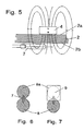
- Fig. 3
- eine Draufsicht auf einen zur Betätigung vorgesehenen Dauermagneten;
- Fig. 4
- einen senkrechten Schnitt durch den Dauermagneten nach Fig. 3;
- Fig. 5
- eine schematische Ansicht der Funktion der erfindungsgemäß ausgeführten Schaltvorrichtung;
- Fig. 6
- eine Zeichnung zur Erläuterung des Betätigungsbereiches eines Reedkontaktes;
- Fig. 7
- eine ähnliche Ansicht wie in Fig. 6, jedoch mit einem Abschirmblech zur Einschränkung des Betätigungsbereiches;
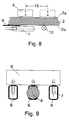
- Fig. 8
- eine schematische Ansicht zur Erläuterung des eingegrenzten Betätigungsbereiches entsprechend Fig. 7; und
- Fig. 9
- eine schematische Darstellung von nebeneinander angeordneten Betätigungsfeldern unter Verwendung eines gemeinsamen Bleches zum Einschränken der Betätigungsbereiche.
- In Fig. 1 ist schematisch eine Einrichtung für Feuchträume gezeigt, insbesondere eine Bade- oder Whirlpoolwanne 1 im senkrechten Schnitt. Unterhalb des Wannenrandes ist eine Schaltvorrichtung 3 vorgesehen, die über einen Dauermagneten 4 betätigt werden kann. Die Wandung der Wanne 1 wird allgemein als Trennwand 2 bezeichnet und schließt den Wannenrand ein. Zur klaren Unterscheidung ist die Feuchtraumseite der Wanne 1 als Außenseite 2a und die auf der Trennwand 2 gegenüberliegende Seite als Innenseite 2b bezeichnet. Die Schaltvorrichtung 3 ist also auf der Innenseite 2b angeordnet, während die Betätigung von der Außenseite 2a her mittels des Dauermagneten 4 erfolgt.
- Fig. 2 zeigt einen Ausschnitt aus dem Wannenrand nach Fig. 1. Es ist zu erkennen, daß auf der Oberfläche 5 mehrere Betätigungsfelder 6 angedeutet sind, unterhalb denen magnetisch betätigbare Schaltelemente 7 in Form von Reedkontakten angeordnet sind. Durch Aufsetzen des Dauermagneten 4 auf eines der Betätigungsfelder 6 wird der zugeordnete Reedkontakt 7 betätigt.
- Neben den Betätigungsfeldern 6 ist noch ein Ablagefeld 16 vorgesehen, um den Dauermagneten 4 bei Nichtgebrauch hierauf abzulegen. Unterhalb dieses Ablagefeldes 16 ist auf der Innenseite 2b ein Eisenblech 12 befestigt, so daß der Dauermagnet im Bereich des Ablagefeldes 16 magnetisch gehaltert wird.
- Fig. 5 zeigt nun, wie durch den Dauermagneten 4 von der Außenseite 2a her durch die Trennwand 2 hindurch der auf der Innenseite 2b angeordnete Reedkontakt 7 magnetisch beeinflußt und somit betätigt werden kann. Hierzu ist es selbstverständlich erforderlich, daß die Trennwand aus magnetisch durchlässigem Material besteht, z.B. Kunststoff, insbesondere Acrylglas. Es ist weiter zu sehen, daß der Dauermagnet 4 in senkrechter Richtung zur Oberfläche 5 der Trennwand 2 polarisiert ist.
- Fig. 6 zeigt nun die Betätigungsbereiche, in denen der Reedkontakt 7 durch Annähern bzw. Aufsetzen des Dauermagneten 4 betätigt werden kann. Die schraffierten Flächen bilden die Form einer Acht, was bedeutet, daß etwa im mittleren Bereich des Reedkontaktes 7 keine Betätigung möglich ist. Es ist also erforderlich, daß zur Betätigung des Reedkontaktes 7 der Dauermagnet 4 im Bereich der schraffierten Betätigungsbereiche 8 bzw. 8a aufgesetzt wird. Um die Bedienungspersonen der Schaltvorrichtung nicht zu irritieren, ist es bei einer solchen achtförmigen Form des Betätigungsbereiches 8, 8a sinnvoll, nur die eine Hälfte, z.B. 8, durch Betatigungsfelder 6 auf der Oberfläche 5 der Trennwand 2 zu markieren, damit die Bedienungsperson den Dauermagneten 4 nicht fälschlicherweise im mittleren Bereich aufsetzt und somit keine sichere Schaltfunktion auslöst. In Fig. 2 sind die nicht mit Betätigungsfeldern 6 markierten Betätigungsbereiche 8a gestrichelt angedeutet.
- Eine bevorzugte Lösung des vorstehend beschriebenen Problems besteht jedoch darin, daß die eine Hälfte der Betätigungsbereiche 8, 8a durch ein magnetisch leitendes Abschirmblech 9 abgedeckt wird, siehe hierzu die Fig. 7 und 8. Somit ergibt sich ein etwa kreisförmiger wirksamer Betätigungsbereich 8, innerhalb dessen der Dauermagnet 4 zwecks Betätigung leicht positioniert werden kann. In Fig. 8 ist außerdem dargestellt, daß der Dauermagnet 4 zwischen der ausgezogenen Position und der gestrichelten Position positioniert werden kann, ohne daß die Schaltsicherheit darunter leidet. Dieser maximale Bereich ist durch das Bezugszeichen 13 angedeutet und die Breite und Länge der Betätigungsfelder 6 (siehe Fig. 2 und 9) werden durch diesen Abstand 13 bestimmt.
- In Fig. 8 ist auch eine jedem Schaltelement 7 zugeordnete Leuchte 10 schematisch angedeutet, die von der Schaltvorrichtung gesteuert, ein Quittungssignal für die Betätigung des zugeordneten Kontaktes 7 liefert. Diese Leucht kann entweder eine Glühlampe oder eine Leuchtdiode sein.
- Fig. 9 zeigt eine bevorzugte Ausführungsform mit drei Reedkontakten 7 und entsprechend drei Betätigungsfeldern 6. Die eine Hälfte der Betätigungsbereiche ist durch ein allen Schaltelementen gemeinsames Abschirmblech 9 abgedeckt, so daß nur eine Hälfte der achförmigen Betätigungsbereiche 8, 8a (siehe Fig. 6 und 7) wirksam ist.
- Die praktische Erprobung hat ergeben, daß die Breite des Betätigungsbereiches 13 (siehe Fig. 8) bei einer Materialstärke der Trennwand 2 von 8 mm etwa 20 mm beträgt, so daß eine unkritische Betätigung der Schaltelemente durch den Dauermagneten 4 möglich ist. Die Reedkontakte 7 steuern vorzugsweise eine Entprellungschaltung in der Schaltvorrichtung an, um durch Kontaktprellungen keine Fehlschaltvorgänge auszulösen. Die Schaltvorrichtung arbeitet vorzugsweise derart, daß der Schaltzustand der gesteuerten elektrischen Geräte bei jeder Betätigung gewechselt wird, d.h., die durch das ansprechende Schaltelement ausgelöste Stellung wird gespeichert.
- In den Fig. 3 und 4 ist gezeigt, daß der Dauermagnet 4 eingekapselt ist, was mit Umspritzen durch Kunststoff 11 erfolgt. Auf diese Weise wird verhindert, daß die feuchten Umgebungsbedingungen das Material des Dauermagneten 4 angreifen bzw. diesen oxidieren lassen.
Claims (6)
- Schaltvorrichtung an Einrichtungen in Feuchträumen, insbesondere Bade- oder Whirlpoolwannen usw., mit mehreren auf der dem Feuchtraum abgekehrten Seite (Innenseite) einer magnetisch durchlässigen Trennwand (2) angeordneten, magnetisch betätigbaren Reedkontakten (7) die durch die Trennwand (2) hindurch von der Feuchtraumseite (Außenseite) her durch Annähern bzw. Aufsetzen eines Dauermagneten (4) an die Betätigungsbereiche der einzelnen Reedkontakte (7) wahlweise betätigbar sind,
dadurch gekennzeichnet,
daß die Betätigungsbereiche (8) der einzelnen Schaltelemente (7) direkt auf der Oberfläche (5) der Trennwand (2) durch entsprechende Betätigungsfelder (6) markiert sind,
daß die Reedkontakte (7) parallel zur Trennwand (2) angeordnet sind und der Dauermagnet (4), in der Betätigungsstellung gesehen, senkrecht zur Oberfläche (5) der Trennwand (2) polarisiert ist,
daß etwa die Hälfte (8a) des Betätigungsbereiches (8, 8a) der Reedkontakte (7) durch ein zwischen den Reedkontakten (7) und der Trennwand (2) angeordnetes Abschirmblech (9) aus magnetisch leitendem Material abgedeckt ist und nur der verbleibende Betätigungsbereich (8) durch ein entsprechendes Betätigungsfeld (6) markiert ist, und daß die markierten Betätigungsfelder (6) sowie die darunter auf der Innenseite angeordneten Reedkontakte (7) einen solchen seitlichen Abstand voneinander haben, daß eine eindeutige wahlweise Betätigung ohne gegenseitige Beeinflussung möglich ist. - Schaltvorrichtung nach Anspruch 1,
dadurch gekennzeichnet, daß die Betätigungsfelder (6) auf der Oberfläche (5) der Trennwand (2) durch Siebdruck oder eine aufgeklebte Folie markiert sind. - Schaltvorrichtung nach Anspruch 1 oder 2,
dadurch gekennzeichnet, daß die Trennwand (2) durch die Wandung einer Bade- oder Whirlpoolwanne (1) gebildet wird, insbesondere durch den oberen Flanschrand der Wanne. - Schaltvorrichtung nach einem der vorstehenden Ansprüche,
dadurch gekennzeichnet, daß auf der Außenseite (2a) der Trennwand (2) außerhalb der Betätigungsfelder (6) ein Ablagefeld (16) zur Ablage des Dauermagneten (4) vorgesehen ist, und daß auf der Innenseite (2b) der Trennwand (2) ein Eisenblech (12) unterhalb dieses Ablagefeldes (16) angeordnet ist. - Schaltvorrichtung nach einem der vorstehenden Ansprüche,
dadurch gekennzeichnet, daß der Dauermagnet (4) hermetisch eingekapselt, vorzugsweise von Kunststoff (11) umspritzt ist. - Schaltvorrichtung nach einem der vorstehenden Ansprüche,
dadurch gekennzeichnet, daß die Trennwand (2) aus durchsichtigem oder durchscheinendem Material besteht und daß unterhalb und im Bereich der Betätigungsfelder (6) auf der Innenseite (2b) Leuchten (10) zur Quittierung der Betätigung der zugeordneten Reedkontakte (7) angeordnet sind.
Applications Claiming Priority (2)
| Application Number | Priority Date | Filing Date | Title |
|---|---|---|---|
| DE4023244 | 1990-07-21 | ||
| DE4023244A DE4023244A1 (de) | 1990-07-21 | 1990-07-21 | Schaltvorrichtung an einrichtungen in feuchtraeumen, insbesondere bade- oder whirlpoolwannen usw. |
Publications (2)
| Publication Number | Publication Date |
|---|---|
| EP0468291A1 EP0468291A1 (de) | 1992-01-29 |
| EP0468291B1 true EP0468291B1 (de) | 1995-06-14 |
Family
ID=6410764
Family Applications (1)
| Application Number | Title | Priority Date | Filing Date |
|---|---|---|---|
| EP91111543A Expired - Lifetime EP0468291B1 (de) | 1990-07-21 | 1991-07-11 | Schaltvorrichtung an Einrichtungen in Feuchträumen, insbesondere Bade- oder Whirlpoolwannen usw. |
Country Status (3)
| Country | Link |
|---|---|
| EP (1) | EP0468291B1 (de) |
| AT (1) | ATE123901T1 (de) |
| DE (2) | DE4023244A1 (de) |
Families Citing this family (3)
| Publication number | Priority date | Publication date | Assignee | Title |
|---|---|---|---|---|
| DE9412140U1 (de) * | 1994-07-27 | 1995-08-24 | Wamsler Großküchentechnik GmbH, 80687 München | Friteuse |
| DE102005063070B4 (de) * | 2005-12-30 | 2012-06-14 | Robert Seuffer Gmbh & Co. Kg | Vorrichtung zum Steuern eines Betriebsparameters eines elektrischen Geräts |
| US10072832B2 (en) | 2015-02-18 | 2018-09-11 | Zodiac Pool Systems Llc | Lighting assemblies |
Family Cites Families (8)
| Publication number | Priority date | Publication date | Assignee | Title |
|---|---|---|---|---|
| DE1827465U (de) * | 1960-10-15 | 1961-03-02 | Siemens Ag | Magnetisch betaetigter endschalter. |
| DE1948380U (de) * | 1966-08-31 | 1966-10-27 | Heinz Baldamus | Elektroschalter fuer indirekte betaetigung. |
| DE2123424A1 (de) * | 1971-05-12 | 1972-11-23 | Blaser, Ernst, 4330 Mülheim | Anordnung zur Übertragung mechanischer Bewegungen aus Druck- oder Vakuumräumen für Mess-, Steuer- und Regeltechnik |
| JPS51119976A (en) * | 1975-04-15 | 1976-10-20 | Futaba Denshi Kogyo Kk | Switching device for reed switch |
| DE2804952A1 (de) * | 1978-02-06 | 1979-08-09 | Siemens Ag | Vorrichtung zur betaetigung eines magnetisch beeinflussbaren schalters |
| US4560838A (en) * | 1984-01-20 | 1985-12-24 | Water Jet Corporation | Apparatus for integrating a plurality of audio systems |
| JPS6343553U (de) * | 1986-09-09 | 1988-03-23 | ||
| EP0283781B1 (de) * | 1987-03-10 | 1993-01-20 | Kabushiki Kaisha Toshiba | Schalteinrichtung |
-
1990
- 1990-07-21 DE DE4023244A patent/DE4023244A1/de not_active Withdrawn
-
1991
- 1991-07-11 EP EP91111543A patent/EP0468291B1/de not_active Expired - Lifetime
- 1991-07-11 DE DE59105688T patent/DE59105688D1/de not_active Expired - Fee Related
- 1991-07-11 AT AT91111543T patent/ATE123901T1/de not_active IP Right Cessation
Also Published As
| Publication number | Publication date |
|---|---|
| EP0468291A1 (de) | 1992-01-29 |
| DE59105688D1 (de) | 1995-07-20 |
| ATE123901T1 (de) | 1995-06-15 |
| DE4023244A1 (de) | 1992-01-30 |
Similar Documents
| Publication | Publication Date | Title |
|---|---|---|
| DE2842622C2 (de) | Bedienungspult | |
| DE3632491A1 (de) | Luftspaltschalterbaugruppe | |
| FR2609320B1 (fr) | Valve a trois voies/deux positions a commande electromagnetique | |
| DE10035592A1 (de) | Anordnung zur Steuerung von elektrisch ansteuerbaren Geräten, insbesondere Elektrowärmegeräten | |
| EP0468291B1 (de) | Schaltvorrichtung an Einrichtungen in Feuchträumen, insbesondere Bade- oder Whirlpoolwannen usw. | |
| DE20007687U1 (de) | Beleuchtungsvorrichtung | |
| EP3232428B1 (de) | Anzeigeelement, anzeigevorrichtung mit einem solchen anzeigeelement und elektrogerät mit einer solchen anzeigevorrichtung | |
| EP0188789A2 (de) | Magnetfeldsensor | |
| DE4404229C2 (de) | Kühlgerät mit einem Schrank und einer Tür, Bedienungs- und/oder Informationselementen in der Tür und elektrischen Einrichtungen im Schrank | |
| DE3822311A1 (de) | Verfahren und vorrichtung zur stromlosen fernbedienung eines schalters in einer elektrischen schaltung sowie fernschalter hierfuer | |
| DE2031015A1 (de) | Kontroll-, insbesondere Alarmanlage | |
| DE10118120C1 (de) | Beleuchtungssystem für Handhaben | |
| DE2537628A1 (de) | Betaetigungswerk einer tastatur zur eingabe von daten und/oder befehlen | |
| EP0152510A1 (de) | Gerät zur Entfeuchtung von Mauerwerk | |
| DE2638613C3 (de) | Einrichtung zur optischen Anzeige | |
| DE69316094T2 (de) | Vorrichtung zum Erkennen der Anwesenheit und/oder die Temperatur eines Lebensmittelzubereitungsgefässes auf einer Glasskeramik-Kochmulde | |
| DE2211061B2 (de) | Elektroinstallation für Räume mit vorgefertigten Wänden | |
| DE3843345C2 (de) | ||
| DE1911814A1 (de) | Anzeigevorrichtung | |
| EP0348667B1 (de) | Fahrradschloss mit Permutationsschliessvorrichtung | |
| DE3843343C2 (de) | ||
| EP0143263A1 (de) | Schlüsselschalter | |
| DE2625780B2 (de) | Elektrischer Schalter mit Beleuchtungseinrichtung | |
| DE3843344C1 (en) | Film-viewing device | |
| DE8530957U1 (de) | Magnetfeldbetätigte Sicherheits-Kontakteinrichtung |
Legal Events
| Date | Code | Title | Description |
|---|---|---|---|
| PUAI | Public reference made under article 153(3) epc to a published international application that has entered the european phase |
Free format text: ORIGINAL CODE: 0009012 |
|
| AK | Designated contracting states |
Kind code of ref document: A1 Designated state(s): AT BE CH DE DK ES FR GB GR IT LI LU NL SE |
|
| 17P | Request for examination filed |
Effective date: 19920504 |
|
| 17Q | First examination report despatched |
Effective date: 19940422 |
|
| GRAA | (expected) grant |
Free format text: ORIGINAL CODE: 0009210 |
|
| AK | Designated contracting states |
Kind code of ref document: B1 Designated state(s): AT BE CH DE DK ES FR GB GR IT LI LU NL SE |
|
| PG25 | Lapsed in a contracting state [announced via postgrant information from national office to epo] |
Ref country code: GR Free format text: LAPSE BECAUSE OF FAILURE TO SUBMIT A TRANSLATION OF THE DESCRIPTION OR TO PAY THE FEE WITHIN THE PRESCRIBED TIME-LIMIT Effective date: 19950614 Ref country code: ES Free format text: THE PATENT HAS BEEN ANNULLED BY A DECISION OF A NATIONAL AUTHORITY Effective date: 19950614 Ref country code: DK Effective date: 19950614 Ref country code: BE Effective date: 19950614 |
|
| REF | Corresponds to: |
Ref document number: 123901 Country of ref document: AT Date of ref document: 19950615 Kind code of ref document: T |
|
| ET | Fr: translation filed | ||
| REF | Corresponds to: |
Ref document number: 59105688 Country of ref document: DE Date of ref document: 19950720 |
|
| PG25 | Lapsed in a contracting state [announced via postgrant information from national office to epo] |
Ref country code: LU Free format text: LAPSE BECAUSE OF NON-PAYMENT OF DUE FEES Effective date: 19950731 |
|
| GBT | Gb: translation of ep patent filed (gb section 77(6)(a)/1977) |
Effective date: 19950713 |
|
| ITF | It: translation for a ep patent filed | ||
| PG25 | Lapsed in a contracting state [announced via postgrant information from national office to epo] |
Ref country code: SE Effective date: 19950914 |
|
| PLBE | No opposition filed within time limit |
Free format text: ORIGINAL CODE: 0009261 |
|
| STAA | Information on the status of an ep patent application or granted ep patent |
Free format text: STATUS: NO OPPOSITION FILED WITHIN TIME LIMIT |
|
| 26N | No opposition filed | ||
| REG | Reference to a national code |
Ref country code: GB Ref legal event code: IF02 |
|
| PGFP | Annual fee paid to national office [announced via postgrant information from national office to epo] |
Ref country code: GB Payment date: 20020902 Year of fee payment: 12 Ref country code: AT Payment date: 20020902 Year of fee payment: 12 |
|
| PGFP | Annual fee paid to national office [announced via postgrant information from national office to epo] |
Ref country code: FR Payment date: 20020910 Year of fee payment: 12 |
|
| PGFP | Annual fee paid to national office [announced via postgrant information from national office to epo] |
Ref country code: NL Payment date: 20020930 Year of fee payment: 12 |
|
| PGFP | Annual fee paid to national office [announced via postgrant information from national office to epo] |
Ref country code: CH Payment date: 20021029 Year of fee payment: 12 |
|
| PG25 | Lapsed in a contracting state [announced via postgrant information from national office to epo] |
Ref country code: GB Free format text: LAPSE BECAUSE OF NON-PAYMENT OF DUE FEES Effective date: 20030711 Ref country code: AT Free format text: LAPSE BECAUSE OF NON-PAYMENT OF DUE FEES Effective date: 20030711 |
|
| PG25 | Lapsed in a contracting state [announced via postgrant information from national office to epo] |
Ref country code: LI Free format text: LAPSE BECAUSE OF NON-PAYMENT OF DUE FEES Effective date: 20030731 Ref country code: CH Free format text: LAPSE BECAUSE OF NON-PAYMENT OF DUE FEES Effective date: 20030731 |
|
| PG25 | Lapsed in a contracting state [announced via postgrant information from national office to epo] |
Ref country code: NL Free format text: LAPSE BECAUSE OF NON-PAYMENT OF DUE FEES Effective date: 20040201 |
|
| GBPC | Gb: european patent ceased through non-payment of renewal fee |
Effective date: 20030711 |
|
| REG | Reference to a national code |
Ref country code: CH Ref legal event code: PL |
|
| PG25 | Lapsed in a contracting state [announced via postgrant information from national office to epo] |
Ref country code: FR Free format text: LAPSE BECAUSE OF NON-PAYMENT OF DUE FEES Effective date: 20040331 |
|
| NLV4 | Nl: lapsed or anulled due to non-payment of the annual fee |
Effective date: 20040201 |
|
| REG | Reference to a national code |
Ref country code: FR Ref legal event code: ST |
|
| PGFP | Annual fee paid to national office [announced via postgrant information from national office to epo] |
Ref country code: DE Payment date: 20040928 Year of fee payment: 14 |
|
| PG25 | Lapsed in a contracting state [announced via postgrant information from national office to epo] |
Ref country code: IT Free format text: LAPSE BECAUSE OF NON-PAYMENT OF DUE FEES;WARNING: LAPSES OF ITALIAN PATENTS WITH EFFECTIVE DATE BEFORE 2007 MAY HAVE OCCURRED AT ANY TIME BEFORE 2007. THE CORRECT EFFECTIVE DATE MAY BE DIFFERENT FROM THE ONE RECORDED. Effective date: 20050711 |
|
| PG25 | Lapsed in a contracting state [announced via postgrant information from national office to epo] |
Ref country code: DE Free format text: LAPSE BECAUSE OF NON-PAYMENT OF DUE FEES Effective date: 20060201 |