EP0468610A2 - Methode und Gerät zur Geräuschunterdrückung in Kopfhörern - Google Patents
Methode und Gerät zur Geräuschunterdrückung in Kopfhörern Download PDFInfo
- Publication number
- EP0468610A2 EP0468610A2 EP91250205A EP91250205A EP0468610A2 EP 0468610 A2 EP0468610 A2 EP 0468610A2 EP 91250205 A EP91250205 A EP 91250205A EP 91250205 A EP91250205 A EP 91250205A EP 0468610 A2 EP0468610 A2 EP 0468610A2
- Authority
- EP
- European Patent Office
- Prior art keywords
- transducer
- input
- output
- noise
- ear canal
- Prior art date
- Legal status (The legal status is an assumption and is not a legal conclusion. Google has not performed a legal analysis and makes no representation as to the accuracy of the status listed.)
- Granted
Links
Images



Classifications
-
- H—ELECTRICITY
- H04—ELECTRIC COMMUNICATION TECHNIQUE
- H04R—LOUDSPEAKERS, MICROPHONES, GRAMOPHONE PICK-UPS OR LIKE ACOUSTIC ELECTROMECHANICAL TRANSDUCERS; ELECTRIC HEARING AIDS; PUBLIC ADDRESS SYSTEMS
- H04R1/00—Details of transducers, loudspeakers or microphones
- H04R1/10—Earpieces; Attachments therefor ; Earphones; Monophonic headphones
- H04R1/1083—Reduction of ambient noise
-
- G—PHYSICS
- G10—MUSICAL INSTRUMENTS; ACOUSTICS
- G10K—SOUND-PRODUCING DEVICES; METHODS OR DEVICES FOR PROTECTING AGAINST, OR FOR DAMPING, NOISE OR OTHER ACOUSTIC WAVES IN GENERAL; ACOUSTICS NOT OTHERWISE PROVIDED FOR
- G10K11/00—Methods or devices for transmitting, conducting or directing sound in general; Methods or devices for protecting against, or for damping, noise or other acoustic waves in general
- G10K11/16—Methods or devices for protecting against, or for damping, noise or other acoustic waves in general
- G10K11/175—Methods or devices for protecting against, or for damping, noise or other acoustic waves in general using interference effects; Masking sound
- G10K11/178—Methods or devices for protecting against, or for damping, noise or other acoustic waves in general using interference effects; Masking sound by electro-acoustically regenerating the original acoustic waves in anti-phase
- G10K11/1781—Methods or devices for protecting against, or for damping, noise or other acoustic waves in general using interference effects; Masking sound by electro-acoustically regenerating the original acoustic waves in anti-phase characterised by the analysis of input or output signals, e.g. frequency range, modes, transfer functions
- G10K11/17821—Methods or devices for protecting against, or for damping, noise or other acoustic waves in general using interference effects; Masking sound by electro-acoustically regenerating the original acoustic waves in anti-phase characterised by the analysis of input or output signals, e.g. frequency range, modes, transfer functions characterised by the analysis of the input signals only
- G10K11/17825—Error signals
-
- G—PHYSICS
- G10—MUSICAL INSTRUMENTS; ACOUSTICS
- G10K—SOUND-PRODUCING DEVICES; METHODS OR DEVICES FOR PROTECTING AGAINST, OR FOR DAMPING, NOISE OR OTHER ACOUSTIC WAVES IN GENERAL; ACOUSTICS NOT OTHERWISE PROVIDED FOR
- G10K11/00—Methods or devices for transmitting, conducting or directing sound in general; Methods or devices for protecting against, or for damping, noise or other acoustic waves in general
- G10K11/16—Methods or devices for protecting against, or for damping, noise or other acoustic waves in general
- G10K11/175—Methods or devices for protecting against, or for damping, noise or other acoustic waves in general using interference effects; Masking sound
- G10K11/178—Methods or devices for protecting against, or for damping, noise or other acoustic waves in general using interference effects; Masking sound by electro-acoustically regenerating the original acoustic waves in anti-phase
- G10K11/1783—Methods or devices for protecting against, or for damping, noise or other acoustic waves in general using interference effects; Masking sound by electro-acoustically regenerating the original acoustic waves in anti-phase handling or detecting of non-standard events or conditions, e.g. changing operating modes under specific operating conditions
-
- G—PHYSICS
- G10—MUSICAL INSTRUMENTS; ACOUSTICS
- G10K—SOUND-PRODUCING DEVICES; METHODS OR DEVICES FOR PROTECTING AGAINST, OR FOR DAMPING, NOISE OR OTHER ACOUSTIC WAVES IN GENERAL; ACOUSTICS NOT OTHERWISE PROVIDED FOR
- G10K11/00—Methods or devices for transmitting, conducting or directing sound in general; Methods or devices for protecting against, or for damping, noise or other acoustic waves in general
- G10K11/16—Methods or devices for protecting against, or for damping, noise or other acoustic waves in general
- G10K11/175—Methods or devices for protecting against, or for damping, noise or other acoustic waves in general using interference effects; Masking sound
- G10K11/178—Methods or devices for protecting against, or for damping, noise or other acoustic waves in general using interference effects; Masking sound by electro-acoustically regenerating the original acoustic waves in anti-phase
- G10K11/1785—Methods, e.g. algorithms; Devices
- G10K11/17853—Methods, e.g. algorithms; Devices of the filter
-
- G—PHYSICS
- G10—MUSICAL INSTRUMENTS; ACOUSTICS
- G10K—SOUND-PRODUCING DEVICES; METHODS OR DEVICES FOR PROTECTING AGAINST, OR FOR DAMPING, NOISE OR OTHER ACOUSTIC WAVES IN GENERAL; ACOUSTICS NOT OTHERWISE PROVIDED FOR
- G10K11/00—Methods or devices for transmitting, conducting or directing sound in general; Methods or devices for protecting against, or for damping, noise or other acoustic waves in general
- G10K11/16—Methods or devices for protecting against, or for damping, noise or other acoustic waves in general
- G10K11/175—Methods or devices for protecting against, or for damping, noise or other acoustic waves in general using interference effects; Masking sound
- G10K11/178—Methods or devices for protecting against, or for damping, noise or other acoustic waves in general using interference effects; Masking sound by electro-acoustically regenerating the original acoustic waves in anti-phase
- G10K11/1785—Methods, e.g. algorithms; Devices
- G10K11/17857—Geometric disposition, e.g. placement of microphones
-
- G—PHYSICS
- G10—MUSICAL INSTRUMENTS; ACOUSTICS
- G10K—SOUND-PRODUCING DEVICES; METHODS OR DEVICES FOR PROTECTING AGAINST, OR FOR DAMPING, NOISE OR OTHER ACOUSTIC WAVES IN GENERAL; ACOUSTICS NOT OTHERWISE PROVIDED FOR
- G10K11/00—Methods or devices for transmitting, conducting or directing sound in general; Methods or devices for protecting against, or for damping, noise or other acoustic waves in general
- G10K11/16—Methods or devices for protecting against, or for damping, noise or other acoustic waves in general
- G10K11/175—Methods or devices for protecting against, or for damping, noise or other acoustic waves in general using interference effects; Masking sound
- G10K11/178—Methods or devices for protecting against, or for damping, noise or other acoustic waves in general using interference effects; Masking sound by electro-acoustically regenerating the original acoustic waves in anti-phase
- G10K11/1785—Methods, e.g. algorithms; Devices
- G10K11/17861—Methods, e.g. algorithms; Devices using additional means for damping sound, e.g. using sound absorbing panels
-
- G—PHYSICS
- G10—MUSICAL INSTRUMENTS; ACOUSTICS
- G10K—SOUND-PRODUCING DEVICES; METHODS OR DEVICES FOR PROTECTING AGAINST, OR FOR DAMPING, NOISE OR OTHER ACOUSTIC WAVES IN GENERAL; ACOUSTICS NOT OTHERWISE PROVIDED FOR
- G10K11/00—Methods or devices for transmitting, conducting or directing sound in general; Methods or devices for protecting against, or for damping, noise or other acoustic waves in general
- G10K11/16—Methods or devices for protecting against, or for damping, noise or other acoustic waves in general
- G10K11/175—Methods or devices for protecting against, or for damping, noise or other acoustic waves in general using interference effects; Masking sound
- G10K11/178—Methods or devices for protecting against, or for damping, noise or other acoustic waves in general using interference effects; Masking sound by electro-acoustically regenerating the original acoustic waves in anti-phase
- G10K11/1787—General system configurations
- G10K11/17879—General system configurations using both a reference signal and an error signal
- G10K11/17881—General system configurations using both a reference signal and an error signal the reference signal being an acoustic signal, e.g. recorded with a microphone
-
- G—PHYSICS
- G10—MUSICAL INSTRUMENTS; ACOUSTICS
- G10K—SOUND-PRODUCING DEVICES; METHODS OR DEVICES FOR PROTECTING AGAINST, OR FOR DAMPING, NOISE OR OTHER ACOUSTIC WAVES IN GENERAL; ACOUSTICS NOT OTHERWISE PROVIDED FOR
- G10K11/00—Methods or devices for transmitting, conducting or directing sound in general; Methods or devices for protecting against, or for damping, noise or other acoustic waves in general
- G10K11/16—Methods or devices for protecting against, or for damping, noise or other acoustic waves in general
- G10K11/175—Methods or devices for protecting against, or for damping, noise or other acoustic waves in general using interference effects; Masking sound
- G10K11/178—Methods or devices for protecting against, or for damping, noise or other acoustic waves in general using interference effects; Masking sound by electro-acoustically regenerating the original acoustic waves in anti-phase
- G10K11/1787—General system configurations
- G10K11/17885—General system configurations additionally using a desired external signal, e.g. pass-through audio such as music or speech
-
- H—ELECTRICITY
- H04—ELECTRIC COMMUNICATION TECHNIQUE
- H04R—LOUDSPEAKERS, MICROPHONES, GRAMOPHONE PICK-UPS OR LIKE ACOUSTIC ELECTROMECHANICAL TRANSDUCERS; ELECTRIC HEARING AIDS; PUBLIC ADDRESS SYSTEMS
- H04R3/00—Circuits for transducers
- H04R3/005—Circuits for transducers for combining the signals of two or more microphones
-
- A—HUMAN NECESSITIES
- A61—MEDICAL OR VETERINARY SCIENCE; HYGIENE
- A61F—FILTERS IMPLANTABLE INTO BLOOD VESSELS; PROSTHESES; DEVICES PROVIDING PATENCY TO, OR PREVENTING COLLAPSING OF, TUBULAR STRUCTURES OF THE BODY, e.g. STENTS; ORTHOPAEDIC, NURSING OR CONTRACEPTIVE DEVICES; FOMENTATION; TREATMENT OR PROTECTION OF EYES OR EARS; BANDAGES, DRESSINGS OR ABSORBENT PADS; FIRST-AID KITS
- A61F11/00—Methods or devices for treatment of the ears or hearing sense; Non-electric hearing aids; Methods or devices for enabling ear patients to achieve auditory perception through physiological senses other than hearing sense; Protective devices for the ears, carried on the body or in the hand
- A61F11/06—Protective devices for the ears
- A61F11/14—Protective devices for the ears external, e.g. earcaps or earmuffs
- A61F11/145—Protective devices for the ears external, e.g. earcaps or earmuffs electric, e.g. for active noise reduction
-
- B—PERFORMING OPERATIONS; TRANSPORTING
- B60—VEHICLES IN GENERAL
- B60G—VEHICLE SUSPENSION ARRANGEMENTS
- B60G2400/00—Indexing codes relating to detected, measured or calculated conditions or factors
- B60G2400/60—Load
- B60G2400/61—Load distribution
-
- B—PERFORMING OPERATIONS; TRANSPORTING
- B60—VEHICLES IN GENERAL
- B60G—VEHICLE SUSPENSION ARRANGEMENTS
- B60G2800/00—Indexing codes relating to the type of movement or to the condition of the vehicle and to the end result to be achieved by the control action
- B60G2800/01—Attitude or posture control
- B60G2800/012—Rolling condition
-
- G—PHYSICS
- G10—MUSICAL INSTRUMENTS; ACOUSTICS
- G10K—SOUND-PRODUCING DEVICES; METHODS OR DEVICES FOR PROTECTING AGAINST, OR FOR DAMPING, NOISE OR OTHER ACOUSTIC WAVES IN GENERAL; ACOUSTICS NOT OTHERWISE PROVIDED FOR
- G10K2210/00—Details of active noise control [ANC] covered by G10K11/178 but not provided for in any of its subgroups
- G10K2210/10—Applications
- G10K2210/108—Communication systems, e.g. where useful sound is kept and noise is cancelled
-
- G—PHYSICS
- G10—MUSICAL INSTRUMENTS; ACOUSTICS
- G10K—SOUND-PRODUCING DEVICES; METHODS OR DEVICES FOR PROTECTING AGAINST, OR FOR DAMPING, NOISE OR OTHER ACOUSTIC WAVES IN GENERAL; ACOUSTICS NOT OTHERWISE PROVIDED FOR
- G10K2210/00—Details of active noise control [ANC] covered by G10K11/178 but not provided for in any of its subgroups
- G10K2210/10—Applications
- G10K2210/108—Communication systems, e.g. where useful sound is kept and noise is cancelled
- G10K2210/1081—Earphones, e.g. for telephones, ear protectors or headsets
-
- G—PHYSICS
- G10—MUSICAL INSTRUMENTS; ACOUSTICS
- G10K—SOUND-PRODUCING DEVICES; METHODS OR DEVICES FOR PROTECTING AGAINST, OR FOR DAMPING, NOISE OR OTHER ACOUSTIC WAVES IN GENERAL; ACOUSTICS NOT OTHERWISE PROVIDED FOR
- G10K2210/00—Details of active noise control [ANC] covered by G10K11/178 but not provided for in any of its subgroups
- G10K2210/30—Means
- G10K2210/301—Computational
- G10K2210/3013—Analogue, i.e. using analogue computers or circuits
-
- G—PHYSICS
- G10—MUSICAL INSTRUMENTS; ACOUSTICS
- G10K—SOUND-PRODUCING DEVICES; METHODS OR DEVICES FOR PROTECTING AGAINST, OR FOR DAMPING, NOISE OR OTHER ACOUSTIC WAVES IN GENERAL; ACOUSTICS NOT OTHERWISE PROVIDED FOR
- G10K2210/00—Details of active noise control [ANC] covered by G10K11/178 but not provided for in any of its subgroups
- G10K2210/30—Means
- G10K2210/301—Computational
- G10K2210/3019—Cross-terms between multiple in's and out's
-
- G—PHYSICS
- G10—MUSICAL INSTRUMENTS; ACOUSTICS
- G10K—SOUND-PRODUCING DEVICES; METHODS OR DEVICES FOR PROTECTING AGAINST, OR FOR DAMPING, NOISE OR OTHER ACOUSTIC WAVES IN GENERAL; ACOUSTICS NOT OTHERWISE PROVIDED FOR
- G10K2210/00—Details of active noise control [ANC] covered by G10K11/178 but not provided for in any of its subgroups
- G10K2210/30—Means
- G10K2210/301—Computational
- G10K2210/3045—Multiple acoustic inputs, single acoustic output
-
- G—PHYSICS
- G10—MUSICAL INSTRUMENTS; ACOUSTICS
- G10K—SOUND-PRODUCING DEVICES; METHODS OR DEVICES FOR PROTECTING AGAINST, OR FOR DAMPING, NOISE OR OTHER ACOUSTIC WAVES IN GENERAL; ACOUSTICS NOT OTHERWISE PROVIDED FOR
- G10K2210/00—Details of active noise control [ANC] covered by G10K11/178 but not provided for in any of its subgroups
- G10K2210/30—Means
- G10K2210/321—Physical
- G10K2210/3214—Architectures, e.g. special constructional features or arrangements of features
-
- H—ELECTRICITY
- H04—ELECTRIC COMMUNICATION TECHNIQUE
- H04R—LOUDSPEAKERS, MICROPHONES, GRAMOPHONE PICK-UPS OR LIKE ACOUSTIC ELECTROMECHANICAL TRANSDUCERS; ELECTRIC HEARING AIDS; PUBLIC ADDRESS SYSTEMS
- H04R1/00—Details of transducers, loudspeakers or microphones
- H04R1/10—Earpieces; Attachments therefor ; Earphones; Monophonic headphones
- H04R1/1008—Earpieces of the supra-aural or circum-aural type
-
- H—ELECTRICITY
- H04—ELECTRIC COMMUNICATION TECHNIQUE
- H04R—LOUDSPEAKERS, MICROPHONES, GRAMOPHONE PICK-UPS OR LIKE ACOUSTIC ELECTROMECHANICAL TRANSDUCERS; ELECTRIC HEARING AIDS; PUBLIC ADDRESS SYSTEMS
- H04R5/00—Stereophonic arrangements
- H04R5/033—Headphones for stereophonic communication
Definitions
- This invention relates to electroacoustic devices for performing noise cancellation, communication interfacing, sound filtering, and headphone functions for the human ear.
- an incoming noise (a sound wave) is sensed and an opposing sound wave is generated which has the same amplitude and frequency but which is 180° out of phase with the incoming wave. The result is that the incoming wave is cancelled when it meets the opposing wave.
- Sensing of the incoming wave is typically performed by an input transducer which converts the incoming noise into a corresponding electrical signal.
- the electrical signal is then typically phase shifted by 180° (inverted) by electrical circuitry.
- An output transducer then typically converts the phase shifted electrical signal into the opposing sound wave.
- U.S. Patent Number 4,455,675 issued to Bose et al. discloses a headphone which uses a donut-like shaped sound attenuating cushion to form a cavity in a volume bounded by the cushion, the user's ear canal, and the headphone.
- This cavity contains one output transducer and one input transducer.
- the input transducer is located facing the ear between the output transducer diaphragm and the entrance to the ear canal.
- the cushion is made from a material which attenuates middle range frequencies around 2kHz so that the cavity is somewhat acoustically isolated from the outside environment.
- U.S. Patent Number 4,644,581 issued to Sapiejewski also discloses a headphone in which a donut-shaped cushion made of a damping material seals with a user's ear pinna to create a cavity continuous with the ear canal.
- an additional piece of damping material is used. This additional piece of damping material, which attenuates high frequency resonances, is positioned to further separate the cavity into a headphone cavity containing the transducers and an ear canal cavity.
- Sapiejewski shows the input transducer and the output transducer oriented perpendicular to each other inside the headphone cavity. The pickup surface of the input transducer does not face the ear cavity.
- An earlier invention involves a composite transducer assembly with an input transducer and an output transducer.
- the input transducer is oriented facing out from the ear and toward the source of noise to be cancelled.
- the output transducer is oriented to face in the opposite direction toward the ear canal of the user.
- Transducers are not ideal. Specifically, input transducers such as small electret microphones have a different phase response from output transducers such as small headphone type speakers. Similarly, output transducers such as a small headphone type speakers have a characteristic roll-off in output amplitude versus frequency of the input electrical signal. This roll-off occurs at low frequencies.
- electret microphones have a reasonably flat amplitude versus frequency response over a wide range of the audio frequency spectrum (eg. +/- 3Db 20Hz - 16KHz). Due to the way an electret microphone is made, several problems exist in making it the ideal input device for use with an output transducer such as a small headphone type speaker.
- An electret microphone element is basically a variable capacitor with a FET semiconductor to convert the changing capacitance into an electrical signal. As sound pressure is applied to the input diaphragm of the electret microphone, it changes capacitance in relation to the varying pressure. This capacitance variation is converted into a corresponding electrical signal by the FET semiconductor. The FET requires a DC voltage to operate. The output of the FET is then presented to the input of a preamplifier for further amplification to raise the signal to a usable level.
- the phase of the signal output by the FET may not be the same as the phase of the signal that would be output by an output transducer such as a small headphone type speaker.
- This different phase relationships of the input transducer and the output transducer produce an error in the desired exact 180° phase shift desired between the input and output transducers. This error then does not allow complete cancellation of the source signal that reaches the ear canal.
- Another problem that causes a phase shift difference between the input transducer and the output transducer is the use of a coupling capacitor between the electret microphone and its preamplifier.
- IC integrated circuit
- This maximum supply voltage also dictates the maximum output signal that can be generated by the IC. With a supply voltage of +/- 18VDC, the maximum signal swing that could be generated would be 36 volts. To amplify the signal from the input transducer to a usable level, amplification factors or gains of 500 to 1000 are needed. Since the electret microphone requires a DC voltage in the range of 2 to 10 volts to operate, the preamplifier IC would need to produce an output signal of 1000 to 2000 volts. This is of course not possible, so the DC supply voltage for the electret microphone can not be presented to the preamplifier for amplification. A capacitor is therefore used to block the DC voltage from the input to the preamplifier.
- This capacitor introduces a phase shift in the signal, thereby adding an error between the input transducer and the output transducer phase coherence.
- Some ICs can be offset by a given amount which corrects this problem, but the phase and the frequency response of the preamplifier IC working at the required gains is then altered resulting in another source of phase error. If an IC was capable of offsetting the supply voltage to the input transducer and amplifying the signal to the required level with flat amplitude and phase versus frequency response, it would be the ideal device for a preamplifier.
- the output transducer also has problems that introduce error in the desired processed signal output.
- a output transducer such as a speaker does not have a flat amplitude versus frequency response over the same audio spectrum as the input transducer. This results in an error in the amplitude summation of the original source signal and the signal output by the output transducer. If the signals are not the exact same amplitude and 180° out of phase, complete cancellation is not achieved.
- Output transducers such as small headphone type speakers roll-off at the lower frequencies. This does not allow complete cancellation of all frequencies.
- the low frequency response of the output transducer can be increased with the use of an enclosure to the back side of the output transducer much like a stereo loudspeaker uses to extend its low frequency response.
- the enclosure has to have a certain internal volume of air and would be bulky and heavy.
- the intent of the composite transducer is to be as small and light weight as possible. It is possible, however, for an enclosure to be put on the composite transducer which extends the low frequency response using materials such as plastic for weight reasons. If an enclosure is used to extend the response, it is still necessary for the original source signal to reach the input transducer at the same time as it reaches the ear canal.
- the less than ideal characteristics of the transducers affect the noise cancellation as the frequency of the input noise changes. If the gain and phase of the amplifier amplifying the output from the input transducer is changed so that the low frequency noise is cancelled, an incorrect electrical signal will then drive the speaker for high frequency noise. The low frequency components of the noise would be better cancelled but the high frequency components would not.
- This invention adds a second input transducer to the composite transducer disclosed in the earlier invention.
- the second input transducer is oriented in the opposite direction from the first input transducer.
- the second transducer lies in the plane of the input and output transducers of the parent application, but faces the ear canal cavity so that it detects the residual uncancelled noise present inside the ear canal cavity.
- the second input transducer After detecting the residual noise, the second input transducer outputs a signal to the electrical circuitry in the control unit of the invention so that an opposing sound wave 180° out of phase with the residual noise will be input into the ear canal cavity by the output transducer.
- the second input transducer because it is oriented to transduce acoustic waves in the ear canal cavity, also picks up the cancelling opposing sound waves being generated by the output transducer. These opposing waves are cancelling noise as desired and therefore should not themselves be cancelled. Because the residual input transducer should only provide cancelling of a part of the frequency range due to imperfections in the amplitude and phase response of the first transducer versus the output transducer, the output of the residual second input transducer is filtered. Accordingly, the portion of the electrical output from the second transducer which is due to the opposing sound waves generated by the output transducer is filtered from the portion of the electrical output due to the residual noise to be cancelled.
- This invention is an "open air" type device in that an ear muff need not provided, nor is a attenuating ear-cavity-forming foam cushion required. Rather, a non-attenuating open cell foam cushion covers the surface of the composite transducer. When the composite transducer is placed against the ear in use, the foam provides a cushion, windscreen, and spacer between the ear pinna of the user and the rest of the composite transducer assembly of the headphone.
- the electrical circuitry of the control unit of the present invention is similar to the circuitry disclosed in the parent application except that it has an input for receiving the electrical output from the second input transducer. It therefore drives the diaphragm of the output transducer based on both the noise detected by the first input transducer and also the residual noise detected by the second input transducer.
- the electronics of the present invention merely inverts the incoming noise to generate a cancelling 180° phase shifted acoustic wave into the ear canal.
- the composite transducer is, however, an "open air" device. Noise to be cancelled therefore travels from the noise source, around the sound-blocking composite transducer, through the foam between the composite transducer and the ear, and into the ear canal.
- the path of the noise from the noise source, through the electronics, and into ear canal is a shorter distance.
- the path from the noise source, through the device, and into the ear canal has a still shorter effective distance when compared to the path of the noise to be cancelled.
- the present invention therefore adds a baffle between the noise source and the electronics, around which the noise picked up by the electronics must first travel.
- the baffle therefore, increases the distance the noise travels before it is picked up and processed by the electronics. Accordingly, with the use of the baffle, the "open air" device of the present invention is able to utilize simple inverting circuitry and still output cancelling acoustic waves which are 180° out of phase with respect to the noise to be cancelled.
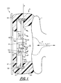
- FIGURE 1 is side cross sectional view showing the composite transducer assembly 100 of the electroacoustic device when in use on the ear pinna 1 of a user.
- First input transducer 34 is oriented so that it receives noise sound waves through conical horn 62.
- Conical horn 62 is provided to avoid standing sound waves of resonances from forming in what would otherwise be a cylindrical tube.
- the incoming noise sound waves received by the first input transducer 34 are depicted as arrow 11.
- Second input transducer 35 is oriented facing in the opposite direction facing ear canal cavity 2 so that it receives residual noise sound waves inside ear canal cavity 2.
- the acoustic waves propagating from the ear canal are depicted emanating in direction 12.
- Both the first and second input transducers 34 and 35 are fixed to frame structure 47 so that the surfaces of the input transducers upon which the sound waves are incident lie in substantially the same plane P.
- Fixing the input transducers in the same plane is accomplished in the embodiment of Figure 1 by first securing the input transducers 34 and 35 to a center disc 43 with glue 43A.
- This glue forms an airtight seal between the ear-facing side of the transducer assembly and the outward-facing side of the transducer assembly.
- Numerous compounds can be used to fix the transducers to center disc 43. Silicon sealant and epoxy glue have been found to be suitable.
- Center disc 43 is then fixed to the frame structure 47. Center disc 43 is not required, however, and the input transducers 34 and 35 can be directly fixed to the frame structure 47 without any such center disc 43.
- Diaphragm 44 of output transducer 36 is oriented to face inwardly toward ear pinna 1 in the same direction that second input transducer 35 faces. Output transducer 36 therefore produces acoustic waves which propagate in the direction of the ear pinna 1 and ear canal cavity 2 as depicted by arrows O.
- Vent ports 58 are provided for equalizing air pressure differences between the ear-facing side of the output transducer diaphragm 44 and the space between diaphragm 44 and frame structure 47 of the composite transducer structure 100.
- Output transducer 36 is operated by coil windings 54 wound on coil form 52 and an associated magnet structure 50.
- a thin profile output transducer is used so that the entire composite transducer assembly has as thin a profile as possible.
- the ear-facing side of the composite transducer is provided with a cushion 30.
- this cushion is made of an open cell foam which does not appreciably attenuate acoustic energy, the cushion does function as a wind screen to impede air flow parallel to plane P between diaphragm 44 and the ear canal cavity 2.
- the cushion 30 also maintains the composite transducer a distance away from the ear pinna 1 in a desired orientation relative to the ear canal cavity 2. Accordingly, both the first input transducer 34 and the second input transducer 35 are disposed adjacent the ear canal cavity 2 and output transducer diaphragm 44 is disposed substantially perpendicular to the direction E of the ear canal.
- cushion 30 serves to space a disc-shaped baffle 64 a distance away from the pickup surface of input transducer 34.
- Baffle 64 serves to impede noise from travelling directly from a source of noise to the input transducer in direction 11. Before noise can reach the pickup surface of the input transducer 34, baffle 64 forces the noise to travel a longer distance around the baffle and through foam 30.
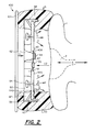
- FIGURE 2 is a side cross sectional view of another composite transducer assembly according the present invention.
- Figure 1 shows the composite transducer assembly using electret type microphones as input transducers
- Figure 2 shows dynamic voice coil type microphones as inputs transducers.
- Figure 1 shows coil form 52, coil windings 54, and the associated magnet structure 50 located at the inner rim 441 of diaphragm 44
- Figure 2 shows coil form 52, coil windings 54, and the associated magnet structure 50 located halfway between inner rim 441 and outer rim 440 of diaphragm 44.
- Figure 1 shows cushion 30 extending only over the outer rim portion of frame structure 47
- Figure 2 shows cushion 30 covering the entire outward-facing side of frame structure 47.
- FIGURE 3 shows the ear-facing side of the composite transducer assembly with the foam cushion 30 and the baffle 64 removed.
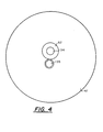
- FIGURE 4 shows the outward-facing side of the composite transducer assembly with the foam cushion 30 and the baffle 64 removed.
- FIGURE 5 is a schematic block diagram of the circuitry of the control unit according to the presently preferred embodiment. The functioning of this circuitry is much the same as the functioning of the circuitry of Figure 4 of the parent application, except for the addition of circuitry associated with the second input transducer 35.
- the first input transducer outputs to a preamplifier 110L which in turn outputs to the positive input of differential mixer amplifier 112L.
- the output of mixer amplifier 112L is inverted by amplifier 112AL which drives output transducer 36L, here denoted as "Speaker". Due to the 180° phase shift in preamplifier 110L, and the subsequent inversion of amplifier 112AL, the inputs the speaker 36L must be reversed so that the speaker itself introduces an additional 180° phase shift.
- the opposing sound waves generated by the output transducer 36L cancel the incoming noise which travels past the plane of the first input transducer. This cancellation occurs over a wide frequency of incoming noise signals using very inexpensive operational amplifier circuitry due to the coplanarity of the input and output transducers.
- Second input transducer 35L transduces residual noise in the ear canal 2 and outputs a corresponding electrical signal to preamplifier 111 L.
- the output of preamplifier 111 proceeds through low pass filter 111AL and into the negative feedback input of mixer amplifier 112L.
- the phase of the acoustic wave incident on the second input transducer 35L is inverted 180° from the phase of the acoustic wave output from speaker 36L.
- the second input transducer is utilized only to cancel low frequency components of the residual noise detected in the ear canal cavity 2.
- Low pass filter 111AL therefore prevents the electrical signal corresponding to any high frequency sound in the ear canal cavity from being supplied to the negative feedback input of mixer 112L.
- the portion of the schematic block diagram of Figure 5 surrounded by the dashed line and labelled "optional" is used to establish a communication link with the user of the invention.
- This portion of the circuitry allows the user to hear himself/herself speak. It also allows the user to listen to intelligence signals input the auxiliary signal input 120L.
- the type of communication link provided is suitable for use in multiple applications such as in aviation.
- the electrical intelligence signal to which the user is to listen is input onto the summing node 112SN via auxiliary signal input 120L and preamplifier 1118L. Because the summing node 112SN is connected to the positive input of mixer 112L, the intelligence signal from the auxiliary signal input is transferred to the speaker 36L for the user to hear.
- a boom microphone 22 is also provided for the communication link so that the user can hear himself/herself speaking and so that speech of the user can be transmitted onto the communication link.
- Boom microphone 22 outputs to preamplifier 134A which outputs to an isolation amplifier 134L which also sums into the summing node 112SN. Accordingly, acoustic waves input into the boom microphone 22 are transferred to speaker 36L so that the user can hear himself/herself speaking.
- the communication link provides an auxiliary signal output 22A for outputting to the communication link an electrical signal indicative of the voice of the user.
- Boom microphone 22 picks up the user's voice and preamplifier 134A outputs the signal to isolation amplifier 134B which drives the corresponding electrical signal out the auxiliary signal output 22A.
- the coplanar positioning of the input transducers and output transducer allows the control circuitry to be simple, inexpensive, and realizable in fast analog circuitry which introduces only a negligible phase shift.
- This analog circuitry is realized with relatively few, inexpensive, readily available monolithic amplifier parts. No special frequency variable delay circuitry is needed to compensate for the differing phase shifts introduced at different noise frequencies which would otherwise be required if the transducers were not oriented in the same plane.
- FIGURE 6 shows a digital alternative to the analog circuit of Figure 5 without the optional communication interface circuitry.
- DSP/aP digital signal processor/micro-processor
- First input transducer 34L and second input transducer 35L output their electrical signals to preamplifier circuits 110L and 111 L, respectively.
- a multiplexing sample and hold and analog- to-digital (A/D) converter chip 200 then sequentially digitizes the electrical signals from preamplifiers 110L and 111 L.
- DSP/tiP 201 reads the digitized values and performs any desired filtering, phase shifting, or mixing with other communications signals.
- the DSP/ ⁇ P then writes to demultiplexing digital-to-analog (D/A) converter 202 so that the filtering output is supplied to amplifier 112AL and to output transducer 36L.
- D/A digital-to-analog
- the digital circuitry of Figure 6 can be presently realized with a high speed sample and hold circuit and A/D converter, digital signal processor, and D/A converter.
- a codec such as the TCM2913 available from Texas Instruments may be used as the A/D converter and the D/A converter.
- a high speed digital signal processor such as the TMS3210 available from Texas Instruments may be used as the DSP/aP.
- Any number of digital filters commonly known in the digital filtering arts could be executed inside DSP/ ⁇ P 201.
- the DSP/ ⁇ P 201 may also be programmed with commonly known filters which have known phase delay versus frequency characteristics. Such filters could be used to delay signal components of specific frequencies to compensate for the non-linear phase versus frequency characteristics of the non-ideal input and output transducers.
- FIGURE 7 shows how disc-shaped baffle 64 of the present invention serves to allow inverting electronics to supply cancelling acoustic waves into the ear canal which are 180° out of phase with respect to the noise to be cancelled.
- the path of the noise to be cancelled is traced from noise source 4 by path D0, past baffle 64, through foam 30, around the solid inside portions of the composite transducer, and to ear canal 2 via path D1.
- This noise travelling path DO plus D1 has a first distance.
- the path of sound to the electronics of the composite transducer and from the electronics to ear canal 2 would be that of dashed path D3 and path D4. Because this is a shorter path than that of the path followed by the noise to be cancelled, 180° inverting electronics would output cancelling acoustic waves which may not be 180° out of phase with respect to the noise entering ear canal 2.
- baffle 64 is added. With this baffle 64, the path of noise which is converted into cancelling acoustic waves can be lengthened. Due to this lengthening, the phase of the acoustic waves output by the electronics into the ear canal can be brought to be 180° out of phase with respect to a broad frequency range of noise entering the ear canal.
- the path of the noise converted into cancelling acoustic waves is traced from noise source 4 by path D0, around baffle 64, through foam 30 to the electronics by path D2, and from the electronics to ear canal 2 by path D4. Accordingly, it is recognized that the phase of the cancelling acoustic waves can be maintained 180° out of phase with respect to the noise entering the ear canal for a broad range of noise frequencies.
Landscapes
- Physics & Mathematics (AREA)
- Engineering & Computer Science (AREA)
- Acoustics & Sound (AREA)
- Multimedia (AREA)
- Health & Medical Sciences (AREA)
- General Health & Medical Sciences (AREA)
- Signal Processing (AREA)
- Otolaryngology (AREA)
- Audiology, Speech & Language Pathology (AREA)
- Life Sciences & Earth Sciences (AREA)
- Biophysics (AREA)
- Psychology (AREA)
- Biomedical Technology (AREA)
- Heart & Thoracic Surgery (AREA)
- Vascular Medicine (AREA)
- Animal Behavior & Ethology (AREA)
- Public Health (AREA)
- Veterinary Medicine (AREA)
- Soundproofing, Sound Blocking, And Sound Damping (AREA)
- Headphones And Earphones (AREA)
- Circuit For Audible Band Transducer (AREA)
Applications Claiming Priority (2)
| Application Number | Priority Date | Filing Date | Title |
|---|---|---|---|
| US558342 | 1990-07-27 | ||
| US07/558,342 US5134659A (en) | 1990-07-10 | 1990-07-27 | Method and apparatus for performing noise cancelling and headphoning |
Publications (3)
| Publication Number | Publication Date |
|---|---|
| EP0468610A2 true EP0468610A2 (de) | 1992-01-29 |
| EP0468610A3 EP0468610A3 (en) | 1992-12-23 |
| EP0468610B1 EP0468610B1 (de) | 1996-02-07 |
Family
ID=24229177
Family Applications (1)
| Application Number | Title | Priority Date | Filing Date |
|---|---|---|---|
| EP91250205A Expired - Lifetime EP0468610B1 (de) | 1990-07-27 | 1991-07-25 | Methode und Gerät zur Geräuschunterdrückung in Kopfhörern |
Country Status (6)
| Country | Link |
|---|---|
| US (1) | US5134659A (de) |
| EP (1) | EP0468610B1 (de) |
| JP (1) | JP3149220B2 (de) |
| AT (1) | ATE134102T1 (de) |
| CA (1) | CA2047855A1 (de) |
| DE (1) | DE69116948T2 (de) |
Cited By (9)
| Publication number | Priority date | Publication date | Assignee | Title |
|---|---|---|---|---|
| GB2265790A (en) * | 1992-04-02 | 1993-10-06 | Polural Limited | Earphone apparatus with active noise reduction |
| GB2267411A (en) * | 1992-05-26 | 1993-12-01 | Mark John Snee | Noise reducing earphone with combined microphone/loudspeaker |
| EP0590869A1 (de) * | 1992-09-30 | 1994-04-06 | AT&T Corp. | Fernsprechhandapparat mit Rauschunterdrückung |
| EP0582404A3 (en) * | 1992-08-03 | 1995-12-06 | American Telephone & Telegraph | Telephonic headset structure for reducing ambient noise |
| EP0661903A3 (de) * | 1993-12-29 | 1996-04-10 | Nec Corp | Telefongerät mit Hintergrundgeräuschunterdrückungsfunktion. |
| EP0967592A3 (de) * | 1993-06-23 | 2000-03-15 | Noise Cancellation Technologies, Inc. | Aktive Lärmunterdruckungsanordnung mit variabler Verstärkung und verbesserter Restlärmmessung |
| WO2006128768A1 (en) * | 2005-06-03 | 2006-12-07 | Thomson Licensing | Loudspeaker driver with integrated microphone |
| WO2011061483A3 (en) * | 2009-11-23 | 2011-08-11 | Incus Laboratories Limited | Production of ambient noise-cancelling earphones |
| GB2462759B (en) * | 2007-05-04 | 2012-04-25 | Mi Sport Global Ltd | Headphones |
Families Citing this family (53)
| Publication number | Priority date | Publication date | Assignee | Title |
|---|---|---|---|---|
| US5327506A (en) * | 1990-04-05 | 1994-07-05 | Stites Iii George M | Voice transmission system and method for high ambient noise conditions |
| US5844984A (en) * | 1992-03-19 | 1998-12-01 | Pan Communications, Inc. | Two-way communications earset with filter |
| US5251263A (en) * | 1992-05-22 | 1993-10-05 | Andrea Electronics Corporation | Adaptive noise cancellation and speech enhancement system and apparatus therefor |
| US5448637A (en) * | 1992-10-20 | 1995-09-05 | Pan Communications, Inc. | Two-way communications earset |
| US5673325A (en) * | 1992-10-29 | 1997-09-30 | Andrea Electronics Corporation | Noise cancellation apparatus |
| US5732143A (en) * | 1992-10-29 | 1998-03-24 | Andrea Electronics Corp. | Noise cancellation apparatus |
| US5715321A (en) * | 1992-10-29 | 1998-02-03 | Andrea Electronics Coporation | Noise cancellation headset for use with stand or worn on ear |
| US7103188B1 (en) | 1993-06-23 | 2006-09-05 | Owen Jones | Variable gain active noise cancelling system with improved residual noise sensing |
| US5497426A (en) * | 1993-11-15 | 1996-03-05 | Jay; Gregory D. | Stethoscopic system for high-noise environments |
| US5526419A (en) * | 1993-12-29 | 1996-06-11 | At&T Corp. | Background noise compensation in a telephone set |
| US5485515A (en) * | 1993-12-29 | 1996-01-16 | At&T Corp. | Background noise compensation in a telephone network |
| US5524058A (en) * | 1994-01-12 | 1996-06-04 | Mnc, Inc. | Apparatus for performing noise cancellation in telephonic devices and headwear |
| US5467775A (en) * | 1995-03-17 | 1995-11-21 | University Research Engineers & Associates | Modular auscultation sensor and telemetry system |
| US5740258A (en) * | 1995-06-05 | 1998-04-14 | Mcnc | Active noise supressors and methods for use in the ear canal |
| US5675658A (en) * | 1995-07-27 | 1997-10-07 | Brittain; Thomas Paige | Active noise reduction headset |
| USD392290S (en) | 1995-10-27 | 1998-03-17 | Andrea Electronics Corporation | Combined boom microphone headset and stand |
| US5740257A (en) * | 1996-12-19 | 1998-04-14 | Lucent Technologies Inc. | Active noise control earpiece being compatible with magnetic coupled hearing aids |
| US5826582A (en) * | 1997-05-22 | 1998-10-27 | Natus Medical Inc. | Ear phone assembly for use with a hearing screener |
| US6272360B1 (en) | 1997-07-03 | 2001-08-07 | Pan Communications, Inc. | Remotely installed transmitter and a hands-free two-way voice terminal device using same |
| US6321070B1 (en) * | 1998-05-14 | 2001-11-20 | Motorola, Inc. | Portable electronic device with a speaker assembly |
| DE19846821B4 (de) * | 1998-10-10 | 2004-04-15 | Daimlerchrysler Ag | Audiokommunikationssystem |
| US6363345B1 (en) | 1999-02-18 | 2002-03-26 | Andrea Electronics Corporation | System, method and apparatus for cancelling noise |
| US6532292B1 (en) * | 1999-03-03 | 2003-03-11 | Sony Corporation | Method and apparatus to transmit audio into the human ear |
| US6597792B1 (en) | 1999-07-15 | 2003-07-22 | Bose Corporation | Headset noise reducing |
| US6594367B1 (en) | 1999-10-25 | 2003-07-15 | Andrea Electronics Corporation | Super directional beamforming design and implementation |
| USD454344S1 (en) | 2000-10-19 | 2002-03-12 | Ume Voice, Inc. | Noise cancellation device for use with recording devices |
| US6826287B2 (en) * | 2001-04-09 | 2004-11-30 | Cabot Safety Intermediate Corporation | Earmuff with controlled leak |
| US7499555B1 (en) * | 2002-12-02 | 2009-03-03 | Plantronics, Inc. | Personal communication method and apparatus with acoustic stray field cancellation |
| US7466838B1 (en) | 2003-12-10 | 2008-12-16 | William T. Moseley | Electroacoustic devices with noise-reducing capability |
| US20050157899A1 (en) * | 2004-01-15 | 2005-07-21 | Gabriel Raviv | Molded earpiece assembly for auditory testing |
| US7412070B2 (en) * | 2004-03-29 | 2008-08-12 | Bose Corporation | Headphoning |
| US7367422B2 (en) * | 2004-05-21 | 2008-05-06 | Brookstone Purchasing. Inc. | System and method for providing passive noise reduction |
| US8077872B2 (en) * | 2005-04-05 | 2011-12-13 | Logitech International, S.A. | Headset visual feedback system |
| US20060269090A1 (en) * | 2005-05-27 | 2006-11-30 | Roman Sapiejewski | Supra-aural headphone noise reducing |
| US8571227B2 (en) | 2005-11-11 | 2013-10-29 | Phitek Systems Limited | Noise cancellation earphone |
| GB2437772B8 (en) | 2006-04-12 | 2008-09-17 | Wolfson Microelectronics Plc | Digital circuit arrangements for ambient noise-reduction. |
| US8249265B2 (en) * | 2006-09-15 | 2012-08-21 | Shumard Eric L | Method and apparatus for achieving active noise reduction |
| US8666085B2 (en) * | 2007-10-02 | 2014-03-04 | Phitek Systems Limited | Component for noise reducing earphone |
| US20090136052A1 (en) * | 2007-11-27 | 2009-05-28 | David Clark Company Incorporated | Active Noise Cancellation Using a Predictive Approach |
| US20090175463A1 (en) * | 2008-01-08 | 2009-07-09 | Fortune Grand Technology Inc. | Noise-canceling sound playing structure |
| US20110317858A1 (en) * | 2008-05-28 | 2011-12-29 | Yat Yiu Cheung | Hearing aid apparatus |
| EP2129114A3 (de) * | 2008-05-29 | 2011-11-02 | Phitek Systems Limited | Medienerweiterungsmodul |
| US20110002474A1 (en) * | 2009-01-29 | 2011-01-06 | Graeme Colin Fuller | Active Noise Reduction System Control |
| EP2226902A3 (de) * | 2009-03-06 | 2013-03-13 | Phitek Systems Limited | Bordunterhaltungssystemverbinder |
| US20110075331A1 (en) * | 2009-05-04 | 2011-03-31 | Nigel Greig | Media Player Holder |
| US20110188668A1 (en) * | 2009-09-23 | 2011-08-04 | Mark Donaldson | Media delivery system |
| US9818394B2 (en) | 2009-11-30 | 2017-11-14 | Graeme Colin Fuller | Realisation of controller transfer function for active noise cancellation |
| BR112012028245B1 (pt) | 2010-05-17 | 2021-04-20 | Phitek Systems, Ltd. | unidade de suporte do módulo e unidade de exibição de vídeo |
| US9487295B2 (en) | 2010-11-15 | 2016-11-08 | William James Sim | Vehicle media distribution system using optical transmitters |
| JP2014533444A (ja) | 2011-06-01 | 2014-12-11 | フィテック システムズ リミテッドPhitek Systems Limited | 能動騒音低減を組み込むインイヤー型装置 |
| SE537957C2 (sv) * | 2012-06-21 | 2015-12-08 | Hellberg Safety Ab | Hörselskydd |
| US8588453B1 (en) * | 2012-09-04 | 2013-11-19 | Eastern Technologies Holding Limited | Reverse-direction co-axial earphone |
| US9949030B2 (en) * | 2016-06-06 | 2018-04-17 | Bose Corporation | Acoustic device |
Citations (2)
| Publication number | Priority date | Publication date | Assignee | Title |
|---|---|---|---|---|
| GB1530814A (en) | 1977-06-20 | 1978-11-01 | British Aircraft Corp Ltd | Hearing protection devices |
| US4644581A (en) | 1985-06-27 | 1987-02-17 | Bose Corporation | Headphone with sound pressure sensing means |
Family Cites Families (3)
| Publication number | Priority date | Publication date | Assignee | Title |
|---|---|---|---|---|
| GB8517716D0 (en) * | 1985-07-13 | 1985-08-21 | Plessey Co Plc | Noise reduction arrangements |
| FR2595498B1 (fr) * | 1986-03-07 | 1989-06-02 | Centre Nat Rech Scient | Procedes et dispositifs pour attenuer les bruits d'origine externe parvenant au tympan et ameliorer l'intelligibilite des communications electro-acoustiques |
| GB8717043D0 (en) * | 1987-07-20 | 1987-08-26 | Plessey Co Plc | Noise reduction systems |
-
1990
- 1990-07-27 US US07/558,342 patent/US5134659A/en not_active Expired - Fee Related
-
1991
- 1991-07-25 DE DE69116948T patent/DE69116948T2/de not_active Expired - Fee Related
- 1991-07-25 CA CA002047855A patent/CA2047855A1/en not_active Abandoned
- 1991-07-25 AT AT91250205T patent/ATE134102T1/de not_active IP Right Cessation
- 1991-07-25 EP EP91250205A patent/EP0468610B1/de not_active Expired - Lifetime
- 1991-07-29 JP JP27902991A patent/JP3149220B2/ja not_active Expired - Fee Related
Patent Citations (2)
| Publication number | Priority date | Publication date | Assignee | Title |
|---|---|---|---|---|
| GB1530814A (en) | 1977-06-20 | 1978-11-01 | British Aircraft Corp Ltd | Hearing protection devices |
| US4644581A (en) | 1985-06-27 | 1987-02-17 | Bose Corporation | Headphone with sound pressure sensing means |
Cited By (10)
| Publication number | Priority date | Publication date | Assignee | Title |
|---|---|---|---|---|
| GB2265790A (en) * | 1992-04-02 | 1993-10-06 | Polural Limited | Earphone apparatus with active noise reduction |
| GB2267411A (en) * | 1992-05-26 | 1993-12-01 | Mark John Snee | Noise reducing earphone with combined microphone/loudspeaker |
| EP0582404A3 (en) * | 1992-08-03 | 1995-12-06 | American Telephone & Telegraph | Telephonic headset structure for reducing ambient noise |
| EP0590869A1 (de) * | 1992-09-30 | 1994-04-06 | AT&T Corp. | Fernsprechhandapparat mit Rauschunterdrückung |
| EP0967592A3 (de) * | 1993-06-23 | 2000-03-15 | Noise Cancellation Technologies, Inc. | Aktive Lärmunterdruckungsanordnung mit variabler Verstärkung und verbesserter Restlärmmessung |
| EP0661903A3 (de) * | 1993-12-29 | 1996-04-10 | Nec Corp | Telefongerät mit Hintergrundgeräuschunterdrückungsfunktion. |
| US5748725A (en) * | 1993-12-29 | 1998-05-05 | Nec Corporation | Telephone set with background noise suppression function |
| WO2006128768A1 (en) * | 2005-06-03 | 2006-12-07 | Thomson Licensing | Loudspeaker driver with integrated microphone |
| GB2462759B (en) * | 2007-05-04 | 2012-04-25 | Mi Sport Global Ltd | Headphones |
| WO2011061483A3 (en) * | 2009-11-23 | 2011-08-11 | Incus Laboratories Limited | Production of ambient noise-cancelling earphones |
Also Published As
| Publication number | Publication date |
|---|---|
| EP0468610B1 (de) | 1996-02-07 |
| JP3149220B2 (ja) | 2001-03-26 |
| JPH06121386A (ja) | 1994-04-28 |
| CA2047855A1 (en) | 1992-01-28 |
| DE69116948T2 (de) | 1996-09-12 |
| DE69116948D1 (de) | 1996-03-21 |
| US5134659A (en) | 1992-07-28 |
| ATE134102T1 (de) | 1996-02-15 |
| EP0468610A3 (en) | 1992-12-23 |
Similar Documents
| Publication | Publication Date | Title |
|---|---|---|
| US5134659A (en) | Method and apparatus for performing noise cancelling and headphoning | |
| US5138663A (en) | Method and apparatus for performing noise cancelling and headphoning | |
| JP2989843B2 (ja) | アクティブ雑音減少システム | |
| US5001763A (en) | Electroacoustic device for hearing needs including noise cancellation | |
| EP0412902B1 (de) | Elektroakustische Anordnung für Hörgeräte mit Lärmunterdrückung | |
| US7043037B2 (en) | Hearing aid having acoustical feedback protection | |
| KR0129766B1 (ko) | 소음저감수화기장치 | |
| EP0951802B1 (de) | Digitales hörhilfegerät unter verwendung von differenzsignaldarstellungen | |
| JPH0520959B2 (de) | ||
| US6714654B2 (en) | Hearing aid operative to cancel sounds propagating through the hearing aid case | |
| USH417H (en) | Headset for ambient noise suppression | |
| US20030138111A1 (en) | Noise-suppressing receiver | |
| US5335282A (en) | Signal summing non-microphonic differential microphone | |
| CN113286216B (zh) | 音频系统和音频方法 | |
| US20230026002A1 (en) | Non-acoustic sensor for active noise cancellation | |
| JP3391616B2 (ja) | 補聴器 | |
| GB2479359A (en) | Virtual feedback circuit arrangement for ambient noise-cancelling (ANC) earphones | |
| JPH11289591A (ja) | 音響電気信号変換装置 | |
| JPH02231900A (ja) | ヘッドホン装置 | |
| JPH0413900B2 (de) |
Legal Events
| Date | Code | Title | Description |
|---|---|---|---|
| PUAI | Public reference made under article 153(3) epc to a published international application that has entered the european phase |
Free format text: ORIGINAL CODE: 0009012 |
|
| AK | Designated contracting states |
Kind code of ref document: A2 Designated state(s): AT BE CH DE DK ES FR GB GR IT LI LU NL SE |
|
| PUAL | Search report despatched |
Free format text: ORIGINAL CODE: 0009013 |
|
| AK | Designated contracting states |
Kind code of ref document: A3 Designated state(s): AT BE CH DE DK ES FR GB GR IT LI LU NL SE |
|
| 17P | Request for examination filed |
Effective date: 19930604 |
|
| 17Q | First examination report despatched |
Effective date: 19941107 |
|
| GRAA | (expected) grant |
Free format text: ORIGINAL CODE: 0009210 |
|
| AK | Designated contracting states |
Kind code of ref document: B1 Designated state(s): AT BE CH DE DK ES FR GB GR IT LI LU NL SE |
|
| PG25 | Lapsed in a contracting state [announced via postgrant information from national office to epo] |
Ref country code: LI Effective date: 19960207 Ref country code: GR Free format text: LAPSE BECAUSE OF FAILURE TO SUBMIT A TRANSLATION OF THE DESCRIPTION OR TO PAY THE FEE WITHIN THE PRESCRIBED TIME-LIMIT Effective date: 19960207 Ref country code: DK Effective date: 19960207 Ref country code: CH Effective date: 19960207 Ref country code: ES Free format text: THE PATENT HAS BEEN ANNULLED BY A DECISION OF A NATIONAL AUTHORITY Effective date: 19960207 Ref country code: BE Effective date: 19960207 Ref country code: AT Effective date: 19960207 Ref country code: NL Free format text: LAPSE BECAUSE OF FAILURE TO SUBMIT A TRANSLATION OF THE DESCRIPTION OR TO PAY THE FEE WITHIN THE PRESCRIBED TIME-LIMIT Effective date: 19960207 |
|
| REF | Corresponds to: |
Ref document number: 134102 Country of ref document: AT Date of ref document: 19960215 Kind code of ref document: T |
|
| REF | Corresponds to: |
Ref document number: 69116948 Country of ref document: DE Date of ref document: 19960321 |
|
| ET | Fr: translation filed | ||
| ITF | It: translation for a ep patent filed | ||
| PG25 | Lapsed in a contracting state [announced via postgrant information from national office to epo] |
Ref country code: SE Effective date: 19960507 |
|
| NLV1 | Nl: lapsed or annulled due to failure to fulfill the requirements of art. 29p and 29m of the patents act | ||
| PG25 | Lapsed in a contracting state [announced via postgrant information from national office to epo] |
Ref country code: LU Free format text: LAPSE BECAUSE OF NON-PAYMENT OF DUE FEES Effective date: 19960731 |
|
| REG | Reference to a national code |
Ref country code: CH Ref legal event code: PL |
|
| PLBE | No opposition filed within time limit |
Free format text: ORIGINAL CODE: 0009261 |
|
| STAA | Information on the status of an ep patent application or granted ep patent |
Free format text: STATUS: NO OPPOSITION FILED WITHIN TIME LIMIT |
|
| 26N | No opposition filed | ||
| REG | Reference to a national code |
Ref country code: GB Ref legal event code: IF02 |
|
| PGFP | Annual fee paid to national office [announced via postgrant information from national office to epo] |
Ref country code: DE Payment date: 20030916 Year of fee payment: 13 |
|
| PGFP | Annual fee paid to national office [announced via postgrant information from national office to epo] |
Ref country code: FR Payment date: 20040617 Year of fee payment: 14 |
|
| PG25 | Lapsed in a contracting state [announced via postgrant information from national office to epo] |
Ref country code: DE Free format text: LAPSE BECAUSE OF NON-PAYMENT OF DUE FEES Effective date: 20050201 |
|
| PG25 | Lapsed in a contracting state [announced via postgrant information from national office to epo] |
Ref country code: IT Free format text: LAPSE BECAUSE OF NON-PAYMENT OF DUE FEES;WARNING: LAPSES OF ITALIAN PATENTS WITH EFFECTIVE DATE BEFORE 2007 MAY HAVE OCCURRED AT ANY TIME BEFORE 2007. THE CORRECT EFFECTIVE DATE MAY BE DIFFERENT FROM THE ONE RECORDED. Effective date: 20050725 |
|
| PG25 | Lapsed in a contracting state [announced via postgrant information from national office to epo] |
Ref country code: FR Free format text: LAPSE BECAUSE OF NON-PAYMENT OF DUE FEES Effective date: 20060331 |
|
| REG | Reference to a national code |
Ref country code: FR Ref legal event code: ST Effective date: 20060331 |
|
| PGFP | Annual fee paid to national office [announced via postgrant information from national office to epo] |
Ref country code: GB Payment date: 20100706 Year of fee payment: 20 |
|
| REG | Reference to a national code |
Ref country code: GB Ref legal event code: PE20 Expiry date: 20110724 |
|
| PG25 | Lapsed in a contracting state [announced via postgrant information from national office to epo] |
Ref country code: GB Free format text: LAPSE BECAUSE OF EXPIRATION OF PROTECTION Effective date: 20110724 |