EP0468652B1 - Verfahren und Einrichtung zur Bildverarbeitung - Google Patents
Verfahren und Einrichtung zur Bildverarbeitung Download PDFInfo
- Publication number
- EP0468652B1 EP0468652B1 EP91306033A EP91306033A EP0468652B1 EP 0468652 B1 EP0468652 B1 EP 0468652B1 EP 91306033 A EP91306033 A EP 91306033A EP 91306033 A EP91306033 A EP 91306033A EP 0468652 B1 EP0468652 B1 EP 0468652B1
- Authority
- EP
- European Patent Office
- Prior art keywords
- sampling
- pels
- pattern
- sampling pattern
- rows
- Prior art date
- Legal status (The legal status is an assumption and is not a legal conclusion. Google has not performed a legal analysis and makes no representation as to the accuracy of the status listed.)
- Expired - Lifetime
Links
- 238000000034 method Methods 0.000 title claims description 17
- 238000005070 sampling Methods 0.000 claims description 165
- 239000011159 matrix material Substances 0.000 description 5
- 238000005516 engineering process Methods 0.000 description 3
- 238000010586 diagram Methods 0.000 description 2
- 238000003491 array Methods 0.000 description 1
- 230000007547 defect Effects 0.000 description 1
- 239000004973 liquid crystal related substance Substances 0.000 description 1
Images



Classifications
-
- G—PHYSICS
- G09—EDUCATION; CRYPTOGRAPHY; DISPLAY; ADVERTISING; SEALS
- G09G—ARRANGEMENTS OR CIRCUITS FOR CONTROL OF INDICATING DEVICES USING STATIC MEANS TO PRESENT VARIABLE INFORMATION
- G09G5/00—Control arrangements or circuits for visual indicators common to cathode-ray tube indicators and other visual indicators
- G09G5/22—Control arrangements or circuits for visual indicators common to cathode-ray tube indicators and other visual indicators characterised by the display of characters or indicia using display control signals derived from coded signals representing the characters or indicia, e.g. with a character-code memory
- G09G5/24—Generation of individual character patterns
- G09G5/28—Generation of individual character patterns for enhancement of character form, e.g. smoothing
Definitions
- the invention relates to image processing apparatus and method for generating a grayscale output image from a binary input image.
- Bi-level, binary or ON/OFF image representation has been used in cathode ray tube display devices, a plasma display devices, a liquid crystal display devices and various printers to display or print dot matrix patterns of characters.
- a binary value is assigned to each picture element (pel or pixel).
- each pel in the matrix has either a first binary value or a second binary value and therefore can represent black or white.
- the bi-level representation in the matrix raises a stair-step appearance along non-vertical and non-horizontal lines. As the resolution of a displayed or printed image becomes low, the stepped edges become larger and increasingly displeasing to the viewer.
- Fig. 7 shows the concept of the display utilizing the different gray-scale levels.
- a character pattern of a high resolution, such as 88 x 88 dots/character box is stored in a font memory. It is assumed that the character pattern is displayed on a display device of a resolution of 11 x 11 dots/character. In this case a sampling pattern 21 having 8 x 8 sampling windows is used.
- the number of black pels of a portion of the original character image surrounded by one sampling window are counted, and one of eight levels of gray-scale is assigned in accordance with the number of black pels within the sampling window, so that a grayscale pattern 29 is generated. It is used to control the levels of luminance of the display device.
- the display utilizing the grayscale levels solves the stepped edge problem, it raises a new problem when a relatively complicated character, such as the Kanjii character including many horizontal and vertical lines is displayed.
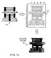
- a Kanji character 51 of high resolution stored in a font memory is shown.
- a sampling pattern having 16 x 16 sampling windows is used.
- the grayscale value is assigned to the number of black pels counted in each sampling window to generate a grayscale pattern 52 representing the original Kanji character 51.
- the grayscale pattern 52 is supplied to the display device. It is apparent that a displayed pattern using the grayscale pattern 52 is of poor quality, includes horizontal lines of the same gray levels contacting each other and has inferior readability.
- the present invention provides an image processing apparatus for generating a grayscale output image from a binary input image, the input image being comprised of a plurality of pels each having one of two possible values associated therewith, the apparatus comprising: means for sampling the input image to assign grayscale values to a number of sampling windows, said sampling windows forming a sampling pattern each sampling window corresponding to a plurality of pels of the input image; characterised by means for determining a position, with respect to the binary input image, for the sampling pattern such that the total number of pels having one of the two possible values associated therewith and falling into a predetermined portion of the sampling pattern is maximised, said assignment being made with the sampling pattern at the determined position.
- the determining means can comprise means for counting said pels having one of the two possible values associated therewith with the sampling pattern at a number of positions with respect to the input image and means for comparing the counted numbers of pels to determine the position at which the counted number is a maximum.
- the sampling windows can be arranged in rows and columns to form the sampling pattern
- the determining means comprising: means for determining, along the column direction, a position for the sampling pattern such that the sum of the number of pels having said one of the values associated therewith falling in a predetermined portion of each row of the sampling pattern is maximised; means for determining, along the row direction, a position for the sampling pattern such that the sum of the number of pels having said one of the values associated therewith falling in a predetermined portion of each column of the sampling pattern is maximised.
- the binary input image is an image of a character and the sampling pattern substantially covers the character.
- an advantageous form of the invention further includes means for detecting rows and/or columns having a greater number of pels having said one of the values associated therewith than the rows and/or colums adjacent thereto; means for determining an optimum position, with respect to the input image, for each said detected row and/or column such that the number of pels having said one of the value associated therewith falling into at least a portion thereof is maximised, the assignment of grayscale values for the sampling windows comprising said detected rows and/or columns being made with said rows and/or columns at their respective optimum positions, the assignment of grayscale values for sampling windows comprising other rows and/or columns being made at said determined position for the sampling pattern.
- a method for generating a grayscale output image from a binary input image the input image being comprised of a plurality of pels each having one of two possible values associated therewith, by sampling the input image to assign grayscale values to a number of sampling windows, said sampling windows forming a sampling pattern
- the method comprising the step of: determining a position, with respect to the binary input image, for the sampling pattern such that the total number of pels having one of two possible values associated therewith falling into at least a portion of the sampling pattern is maximised, said assignment being made with the sampling pattern at the determined position.
- the present invention thus enables the quality and readability of a grayscale pattern generated from a high-resolution character image to be improved.
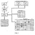
- FIG. 1 a block diagram of the pattern generating system performing the operation in accordance with the present invention is shown.
- a font memory 1 stores a set of original character images or patterns of high resolution. It is assumed that the resolution of the original character image is 88 x 88 dots/character box, and the original character image is converted to a gray-scale pattern of 8 x 8 dots/character box or 8 x 8 pels/character box.
- the pattern generating system can be incorporated in a printer or a display apparatus, and the original character patterns are loaded from a processor to the font memory 1.
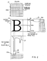
- One of the original character patterns such as image of character B, of 88 x 88 dots resolution is fetched from the font memory 1 to a buffer memory 2 under the control of the microprocessor 3, as shown in Fig. 2.
- the size of the buffer memory 2 shown in the Fig. 1 is equal to the size of one original character box.
- the microprocessor 3 generates a grid-like sampling pattern 21 of 8 x 8 windows, as shown in Fig. 2 based upon the resolution of the original character pattern, i.e. 88 x 88 dots, and the resolution of the gray-scale pattern, i.e. 8 x 8 dots, to be displayed on a display screen.
- the size of the sampling pattern 21 is equal to the size of one character box.
- the microprocessor 3 performs the image converting processes of an algorithm shown in Fig. 3.
- the microprocessor 3 counts the number of black pels in all pel lines in X direction and Y direction of the original character image to generate a histogram 26 in the X direction and a histogram 27 in the Y direction, as shown in the Fig. 2, and stores the histograms 26 and 27 in a histogram buffer memory 4 in the Fig. 1.
- the operation proceeds to a block 32 in the Fig. 3, wherein the microprocessor 3 positions the sampling pattern 21 at an initial position, at which an upper-left corner 22 of the sampling pattern 21 is positioned at an upper-left corner 23 of the dot matrix or character box of the original character image.
- the pel lines 1 through 11 represent the pel lines of the original character image.
- the microprocessor 3 selects a group of pel lines 4, 5, 6, 7 and 8 for each row of the sampling pattern 21.
- the pel line 6 is positioned at a center of the width of row, as shown in the Fig. 4A.
- the microprocessor 3 counts the number of black pels on the group of pel lines 4, 5, 6, 7 and 8 of the original character image of the rows 1 through 8, by referring to the histogram 26 in the histogram buffer memory 4. And, the microprocessor 3 sums up the number of black pels in each row to generate the total number of horizontal black pels of the sampling pattern 21 at the initial position, and stores the total number into a memory position 0 of Y direction of the register 5.
- the microprocessor 3 generates the total number of vertical black pels of the sampling pattern 21 at the initial position. More particularly, Fig. 5A shows an enlarged figure of a portion 28 in the Fig. 2.
- the pel lines 1 through 11 represent the pel lines of the original character image.
- the microprocessor 3 selects a group of pel lines 4, 5, 6 7 and 8 for each column of the sampling pattern 21.
- the pel line 6 is positioned at a center of the width of column, as shown in the Fig. 5A.
- the microprocessor 3 counts the number of black pels on the group of pel lines 4, 5, 6, 7 and 8 of the original character image of the columns 1 through 8, by referring to the histogram 27 in the histogram buffer memory 4. And, the microprocessor 3 sums up the number of black pels in each column to generate the total number of vertical black pels of the sampling pattern 21 at the initial position, and stores the total number into a memory position 0 of X direction of the register 5.
- the operation proceeds to a block 33 in the Fig. 3, wherein the microprocessor 3 sequentially shifts the sampling pattern 21 from the initial position by ⁇ 1 pel line, ⁇ 2 pel lines and ⁇ 3 pel lines in the X and Y directions, respectively, and counts the total number of black pels at each position, in the same manner as that described in the initial position.
- the sampling pattern 21 is upwardly shifted by one pel line.
- the sampling window 25A in the Fig. 4B shows the upward shift of the sampling pattern 21 by one pel line.
- the microprocessor 3 selects a group of pel lines 3, 4, 5, 6 and 7 of the original character image for each row of the sampling pattern 21.
- the microprocessor 3 generates the total number of horizontal black pels of the sampling pattern 21 at the +1 position, and stores the total number into a memory position +1 of Y direction of the register 5.
- the microprocessor 3 selects the pel lines 2, 3, 4, 5 and 6 for the +2 position, the pel lines 1, 2, 3, 4 ad 5 for the +3 position, the pel lines 5, 6, 7, 8 and 9 for the -1 position, the pel lines 6, 7, 8, 9 and 10 for the -2 position, and the pel lines 7, 8, 9, 10 and 11 for the -3 position, respectively. And, the microprocessor 3 generates the total number of horizontal black pels of the sampling pattern 21 at each position, and stores them in the respective memory position of Y direction of the register 5.
- the microprocessor 3 sequentially shifts the sampling pattern 21 from the initial position to the ⁇ 1, ⁇ 2 and ⁇ 3 pel lines in the Y direction, as shown in Fig. 5B.
- the microprocessor 3 selects the pel lines 5, 6, 7, 8 and 9 for the +1 position, the pel lines 6, 7, 8. 9 and 10 for the +2 position, the pel lines 7, 8, 9, 10 and 11 for the +3 position, the pel lines 3, 4, 5, 6 and 7 for the 1 position, the pel lines 2, 3, 4, 5 and 6 for the -2 position, and the pel lines 1, 2, 3, 4 and 5 for the -3 position, respectively.
- the microprocessor 3 generates the total number of vertical black pels of the sampling pattern 21 at each position, and stores them in the respective memory position of X direction of the register 5.
- a range of the shift position in the positive direction or the negative direction is represented by the following formula.
- the +1, +2 and +3 shift positions are selected in the positive direction, and the -1, -2 and -3 shift positions are selected in the negative direction.
- the microprocessor 3 in a block 34 of the Fig. 3, compares the total number stored in each of the memory positions +3, +2, +1, 0, -1, -2 and -3 of the Y direction of the register 5, identifies one position at which the largest value is stored and selects the identified position as a calibrated position of the sampling pattern 21 in the Y direction. It is assumed that the distance between the initial position and the calibrated position of the sampling pattern in the Y direction is Sy, as shown in Fig. 6.
- the microprocessor 3 also compares the total number stored in each of the memory positions +3, +2, +1, 0, -1, -2 and -3 of the X direction of the register 5, identifies one position at which the largest value is stored, and selects the identified position as a calibrated position of the sampling pattern 21 in the X direction. It is assumed that the distance between the initial position and the calibrated position of the sampling pattern 21 in the X direction is Sx, as shown in the Fig. 6.
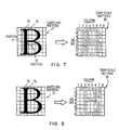
- Fig. 7 shows a gray-scale pattern 29 generated by prior technology using the sampling pattern 21 positioned at the initial position shown in the Fig. 6 without the calibrating operation.
- Fig. 8 shows a gray-scale pattern 30 generated by using the sampling pattern 21 positioned at the calibrated position Sx, Sy shown in the Fig. 6 in accordance with the present invention.
- the portion 71 is represented, in the gray-scale pattern 29, by the gray-scale value 2 in the column 2 and the gray-scale values 5 and 6 in the column 3, while, in the gray-scale pattern 30, the portion 71 is represented by the gray-scale value 7 in the column 3.
- the portion 72 is represented, in the gray-scale pattern 29, by the gray-scale values 2 and 1 in the column 4 and the gray-scale values 4 and 2 in the column 5, while, in the gray-scale pattern 30, the portion 71 is represented by the gray-scale values 3 and 4 in the row 4. It is apparent that the gray-scale pattern 30 generated in accordance with the present invention is of excellent readability in comparison with the gray-scale pattern 29 in the prior art.
- the purpose of the operations performed in the blocks 31, 32, 33 and 34 in the Fig. 3 is to entirely shift or move the sampling pattern 21 on the original character image of the high resolution.
- the border lines of the sampling windows which pass, at the initial position, within the black lines of the character are shifted so as to position the major portion of the black line(s) of the character between the border lines of the sampling windows.
- a border line 73 passes within the portion 71 which is the vertical line of the character B before the entire shift of the sampling pattern 21, as shown in the Fig. 7, whereby the portion 71 is of inferior readability, as shown by the gray-scale pattern 29.
- the portion 71 of the character B is positioned between the border lines 73 and 74 of the sampling pattern 21, as shown in the Fig. 8, so that the portion 71 is of excellent readability, as shown by the gray-scale pattern 30.
- the position of the entire sampling pattern is shifted on the original character image to detect an optimum or calibrated position in the X and/or Y direction at which the total number of black pels on a group of pel lines at the center portion of each of all rows and/or all columns is the largest value.
- the characters are roughly categorized into first group of characters, e.g. alphanumeric, including few horizontal and vertical lines and second group of characters, e.g. Japanese Kanji characters, including many horizontal and vertical lines.
- the entire shift of the sampling pattern 21 performed by the operations in the blocks 31 through 34 in the Fig. 3 improves the readability of the first group of characters, and the readability of the second group of characters, such as Kanji characters, is further improved by the next operation described with referring to Figs. 9 - 13, in addition to the operation in the blocks 31 through 34.
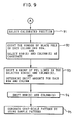
- a block 35 in the Fig. 3 determines as to whether the character being processed is the second group of characters, such as Kanji character, or not.
- the answer of the block 35 is NO, and the operation proceeds to a block 36, wherein the microprocessor 3 positions the sampling pattern 21 at the calibrated position Sx, Sy on the original character pattern, as shown in the Fig. 6, counts the number of black pels surrounded by each sampling window of the sampling pattern 21, and assigns one of the different gray-scale levels or values 0 - 7 to the number of black pels of each sampling window, whereby the gray-scale pattern 30 shown in the Fig. 8 representing the original character B is generated. And, the gray-scale pattern 30 is stored in a buffer memory 6 in the Fig. 1, and is supplied to the display apparatus or the printer.
- the operation proceeds to a block 92, wherein the microprocessor 3 selects the group of pel lines passing through the center portion of each row and column of the sampling pattern 21, and counts the number of black pels on the five pel lines for each row and column of the sampling pattern 21 at the calibrated position Sx, Sy.
- the number of black pels detected in each row and column is shown in the Fig. 10.
- the microprocessor 3 compares the number of black pels in N row with the number of black pels in N-1 row and with the number of black pels in N+1 row respectively, and compares the number of black pels in N column with the number of black pels in N-1 column and with the number of black pels in N+1 column, respectively, to detect the column or row having the number of black pels larger than that of the adjacent ones.
- the microprocessor 3 detects the rows 1, 4 and 7 and the columns 2 and 7, as shown by arrows in the Fig. 10.
- the row 1 has the value 150, i.e. the number of black pels, which is larger than the value zero of an upper adjacent row outside the sampling pattern 21 and the value 60 in the row 2.
- the row 4 has the value 100 which is larger than the value 60 in the row 3 and the value 60 in the row 5.
- the row 7 has the value 110 which is larger than the value 60 in the row 6 and the value 30 in the row 8.
- the column 2 has the value 260 which is larger than the value 0 in the column 1 and the value 70 in the column 3.
- the column 7 has the value 240 which is larger than the value 70 in the column 6 and the value 0 in the column 8. Therefore, the microprocessor 3 selects the columns 2 and 7 and the rows 1, 4 and 7 as candidate row(s) and column(s) to be shifted.
- the operation proceeds to a block 93 in the Fig. 9, wherein the microprocessor 3 shifts the position of the selected rows 1, 4 and 7 and the columns 2 and 7 selected in the block 92.
- the microprocessor 3 performs the shift operation by shifting the position of the five pel lines on the original character image from the position 0 passing through the center of column or row to the +1, +2, -1 and -2 positions, and counts the number of black pels on the five pel lines at each shift position.
- the Fig. 11 shows the sampling windows at columns 2 and 3 in the row 1 of the sampling pattern 21 shown in the Fig. 10. Referring to the column 2 in the Fig. 11, a group of pel lines, i.e.
- the five pel lines is initially located at the position 0 and shifted to the positions +1, +2, -1 and -2, respectively, and the number of black pels on the five pel lines in each of the positions +2, +1, 0, -1, -2 are counted, and stored in the register 7 in the Fig. 1.
- the maximum values for the column 2 are obtained in the shift positions +1 and +2.
- the position +1 nearest to the original position 0 is selected, and stored in the register 7.
- the microprocessor 3 finds out that the shift position -2 generates the maximum value, and stores the column 7 and the position -2 in the register 7.
- the process for the row 1 is described with referring to the Fig. 11, again. It is apparent in the Fig. 11 that the shift position -2 generates the maximum value for the row 1.
- the position -2 for the row 1 is stored in the register 7.
- the microprocessor 3 finds out the maximum value at the positions 0 and -1 for the row 4, and finds out the maximum value at the shift positions -1, 0 and +1 for the row 7.
- the original position 0 is selected when the original position 0 generates the maximum value, so that the microprocessor 3 stores the position 0 into the memory positions labelled "SHIFT" for the rows 4 and 7 of the register 7, as shown in the Fig. 1.
- the microprocessor 3 shifts a group of pel lines within the row and/or column, which is selected in the block 92, of the sampling pattern 21, counts the number of black pels in each position to determine the shift amounts of the row or column.
- shift amounts 0 in the rows 4 and 7 represent that these rows 4 and 7 are not shifted.
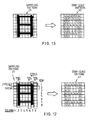
- the operation proceeds to a block 94, wherein the microprocessor 3 shifts the row 1, the column 2 and the column 7 in accordance with the shift values in the register 7 in the Fig. 1. More particularly, the microprocessor 3 shifts the row 1 of the sampling pattern 21 by two pel lines in the downward direction, and shifts the adjacent row 2 by one pel line in the downward direction, as shown in the Fig. 12. The microprocessor 3 shifts the column 2 by one pel line in the rightward direction, as shown in the Fig. 12. The microprocessor 3 shifts the column 7 by two pel lines in the leftward direction, and shifts the adjacent columns 6 and 8 in the leftward direction, as shown in the Fig. 12. The purpose of shifting the adjacent row or column in the same direction is to reduce a distortion of the character image.
- the operation proceeds to a block 95 in the Fig. 9, wherein the microprocessor 3 positions the sampling pattern 21 at the calibrated position Sx, Sy on the original character image decided in the block 34 in the Fig. 3 and shifts the rows and column of the sampling pattern 21, as shown in the Fig. 12, counts the number of black pels surrounded by each sampling window, and assigns one of the different gray-scale levels or values 0 - 7 to the number of black pels of each sampling window, whereby the gray-scale pattern 41 representing the original Kanji character image is generated, as shown in the Fig. 12. And, the gray-scale pattern 41 is stored in the buffer memory 6 in the Fig. 1, and is supplied to the display apparatus or the printer.
- Fig. 13 shows the gray-scale pattern 42 which is generated by using the sampling pattern 21 which is positioned at the calibrated position Sx, Sy detected in the block 34 in the Fig. 3, without the shift of the particular row(s) and column(s) shown in the Fig. 12.
- the position of the selected row(s) and/or column(s) of the sampling pattern at the calibrated position is shifted to the position at which the number of black pels in the selected row and/or column is the largest value.
- a method for generating a low resolution gray-scale pattern representing a high resolution original character image comprises steps of: generating a sampling pattern having plural sampling windows arranged in columns and rows, the number of said columns and rows being determined by a ratio of said low resolution to said high resolution; sequentially positioning said sampling pattern at plural positions separated by a predetermined distance along a column direction on said original character image to count, at each position, the total number of black pels of all rows which is a sum of the number of black pels in a predetermined portion of each row of said sampling pattern; comparing the total number of black pels counted in each of said positions to detect a position at which the largest number of black pels is detected; positioning said sampling pattern at said detected position on said original character pattern; and counting the number of black pels in each sampling window of said sampling pattern to assign one of different gray-scale values to each sampling window.
- a group of pel lines located at a centre portion of said sampling window is used to count the number of black pels in said row.
- said sampling pattern is sequentially positioned at plural positions separated by one pel line.
- the method for generating a low resolution gray-scale pattern representing high resolution original character image in accordance with the present invention comprises steps of: generating a sampling pattern having plural sampling windows arranged in columns and rows, the number of said columns and rows being determined by a ratio of said low resolution to said high resolution; sequentially positioning said sampling pattern at plural positions separated by a predetermined distance along a column direction and a row direction on said original character image to count, at each position, the total number of black pels of all rows which is a sum of the number of black pels in a predetermined portion of each row and the total number of black pels of all columns which is a sum of the number of black pels in a predetermined portion of each column of said sampling pattern; comparing the total number of black pels counted at each of said positions to detect a position in a row direction at which the largest total number of black pels of said all columns is detected and a position in a column direction at which the largest total number of black pels of said all rows is detected; positioning said sampling
- the method for generating a low resolution gray-scale pattern representing a high resolution original character image in accordance with the present invention comprises steps of: generating a sampling pattern having plural sampling windows arranged in columns and rows, the number of said columns and rows being determined by a ratio of said low resolution to said high resolution; sequentially positioning said sampling pattern at plural positions separated by a predetermined distance along a column direction and a row direction on said original character image to count, at each position, the total number of black pels of all rows which is a sum of the number of black pels in a predetermined portion of each row and the total number of black pels of all columns which is a sum of the number of black pels in a predetermined portion of each column of said sampling pattern; comparing the total number of black pels counted at each of said positions to detect a position in a row direction at which the largest total number of black pels of said all columns is detected and a position in a column direction at which the largest total number of black pels of said all rows is detected; positioning
- the invention thus enables the poor quality or inferior readability of the gray-scale pattern generated from the high resolution original character image to be improved.
Landscapes
- Engineering & Computer Science (AREA)
- Physics & Mathematics (AREA)
- Computer Hardware Design (AREA)
- General Physics & Mathematics (AREA)
- Theoretical Computer Science (AREA)
- Controls And Circuits For Display Device (AREA)
- Image Generation (AREA)
Claims (8)
- Einrichtung zur Bildverarbeitung, um ein Graustufenausgangsbild (30) aus einem binären Eingangsbild zu erzeugen, wobei das Eingangsbild eine Vielzahl von Bildelementen enthält, von denen jedes zwei mögliche, damit verbundene Werte hat und die Einrichtung enthält:
Mittel zum Abtasten des Eingangsbilds, um Graustufenwerte einer Anzahl von abgetasteten Fenstern (25A, 25C) zuzuordnen, wobei die abgetasteten Fenster (25A, 25C) ein Abtastmuster (21) bilden und jedes abgetastete Fenster einer Vielzahl von Bildelementen des Eingangsbilds entspricht; gekennzeichnet durch
Mittel zur Bestimmung einer Position bezogen auf das binäre Eingangsbild für das Abtastmuster (21), so daß die Gesamtanzahl von Bildelementen, welche einen Wert von zwei möglichen, damit verbundenen Werten hat und in einen vorbestimmten Teil des Abtastmusters (21) fällt, maximiert wird, wobei die Zuordnung zu dem Abtastmuster (21) in der bestimmten Position erfolgt. - Einrichtung zur Bildverarbeitung wie in Anspruch 1 angemeldet, wobei die Bestimmungsmittel Mittel enthalten, um diese Bildelemente, die einen Wert von zwei möglichen, damit verbundenen Werten haben, zu dem Abtastmuster (21) in einer Anzahl von Positionen bezogen auf das Eingangsbild zu zählen und Mittel, um die gezählten Mengen von Bildelementen zu vergleichen, damit die Position bestimmt werden kann, in welcher die gezählte Menge ein Maximum ergibt.
- Einrichtung zur Bildverarbeitung wie in Anspruch 1 oder 2 angemeldet, wobei die abgetasteten Fenster (25A, 25C) in Reihen und Spalten angeordnet sind, um das Abtastmuster (21) zu bilden, wobei die Bestimmungsmittel enthalten:
Mittel, um entlang der Spalte eine Position für das Abtastmuster (21) zu bestimmen, so daß die Summe der Anzahl von Bildelementen, die einen Wert von den damit verbundenen Werten hat, die in einen vorbestimmten Teil von jeder Reihe des Abtastmusters fällt, maximiert wird;
Mittel, um entlang der Reihe eine Position für das Abtastmuster zu bestimmen, so daß die Summe der Anzahl von Bildelementen, die einen Wert von den damit verbundenen Werten hat, die in einen vorbestimmten Teil von jeder Spalte des Abtastmusters fällt, maximiert wird. - Einrichtung zur Bildverarbeitung wie in Anspruch 3 angemeldet, wobei das binäre Eingangsbild ein Bild eines Zeichens ist und wobei das Abtastmuster (21) hauptsächlich dieses Zeichen abdeckt und die Einrichtung enthält;
Mittel zur Erkennung von Reihen und/oder Spalten, welche eine größere Anzahl von Bildelementen haben, die einen Wert von den damit verbundenen Werten hat, als die daran angrenzenden Reihen und/oder Spalten;
Mittel zur Bestimmung einer optimalen Position in bezug auf das Eingangsbild für jede der erkannten Reihen und/oder Spalten, so daß die Anzahl von Bildelementen, die einen Wert von den damit verbundenen Werten hat, die wenigstens in einen Teil davon fällt, maximiert wird, wobei die Zuordnung der Graustufenwerte für die abgetasteten Fenster (25A, 25C), welche die erkannten Reihen und/oder Spalten enthalten, mit den Reihen und/oder Spalten in ihren jeweiligen optimalen Positionen erstellt wird, wobei die Zuordnung der Graustufenwerte für die abgetasteten Fenster (25A, 25C), welche andere Reihen und/oder Spalten enthalten, in der bestimmten Position für das Abtastmuster erstellt wird. - Ein Verfahren, um ein Graustufenausgangsbild aus einem binären Eingangsbild zu erzeugen, wobei das Eingangsbild eine Vielzahl von Bildelementen enthält, von denen jedes zwei mögliche, damit verbundene Werte hat, indem das Eingangsbild abgetastet wird, um Graustufenwerte einer Anzahl von abgetasteten Fenstern (25A, 25C) zuzuordnen, wobei die abgetasteten Fenster (25A, 25C) ein Abtastmuster (21) bilden und das Verfahren den Schritt
zur Bestimmung (32, 33, 34) einer Position bezogen auf das binäre Eingangsbild für das Abtastmuster enthält, so daß die Gesamtanzahl von Bildelementen, welche einen Wert von zwei möglichen, damit verbundenen Werten hat, wenigstens in einen Teil des Abtastmusters fällt, maximiert wird, wobei die Zuordnung zu dem Abtastmuster in der bestimmten Position erfolgt (36). - Ein Verfahren wie in Anspruch 5 angemeldet, um ein Graustufenmuster mit niedriger Auflösung zu erzeugen, das ein Originalzeichenbild mit hoher Auflösung darstellt, welches Schritte enthält:
zur Erzeugung eines Abtastmusters mit einer Vielzahl von abgetasteten Fenstern, die in Spalten und Reihen angeordnet sind, wobei die Anzahl von Spalten und Reihen durch ein Verhältnis von niedriger Auflösung zu hoher Auflösung bestimmt wird; in welchem der Schritt zur Bestimmung enthält
die sequentielle Positionierung (32, 33) des Abtastmusters in mehreren Positionen, die durch einen vorbestimmten Abstand entlang einer Spalte und einer Reihe in dem Originalzeichenbild getrennt wird, um in jeder Position die Gesamtanzahl von schwarzen Bildelementen in allen Reihen zu zählen, welches eine Summe von der Anzahl von schwarzen Bildelementen in einem vorbestimmten Teil von jeder Reihe ist und die Gesamtanzahl von schwarzen Bildelementen in allen Spalten zu zählen, welches eine Summe von der Anzahl von schwarzen Bildelementen in einem vorbestimmten Teil von jeder Spalte des Abtastmusters ist;
den Vergleich (34) der Gesamtanzahl von schwarzen Bildelementen, die in jeder der Positionen gezählt wurden, um eine Position in einer Reihe zu erkennen, in welcher die größte Gesamtanzahl von schwarzen Bildelementen von allen Spalten erkannt wird, und eine Position in einer Spalte zu erkennen, in welcher die größte Gesamtanzahl von schwarzen Bildelementen von allen Reihen erkannt wird;
die Positionierung des abgetasteten Fensters in der erkannten Position in diesem Originalzeichenmuster; und
das Zählen (36) der Anzahl von schwarzen Bildelementen in jedem abgetasteten Fenster des Abtastmusters, um einen der verschiedenen Graustufenwerte jedem abgetasteten Fenster zuzuordnen. - Ein Verfahren wie in Anspruch 6 angemeldet, wobei eine Gruppe von Bildelementzeilen, welche sich in einem Mittelteil des abgetasteten Fensters befindet, verwendet wird, um die Anzahl von schwarzen Bildelementen in dieser Reihe und Spalte zu zählen.
- Ein Verfahren wie in Anspruch 6 oder Anspruch 7 angemeldet, wobei das Abtastmuster in mehreren Positionen, die durch eine Bildelementzeile getrennt sind, sequentiell positioniert wird.
Applications Claiming Priority (2)
| Application Number | Priority Date | Filing Date | Title |
|---|---|---|---|
| JP2195101A JPH077256B2 (ja) | 1990-07-25 | 1990-07-25 | グレイ・スケール・パターンの発生方法 |
| JP195101/90 | 1990-07-25 |
Publications (3)
| Publication Number | Publication Date |
|---|---|
| EP0468652A2 EP0468652A2 (de) | 1992-01-29 |
| EP0468652A3 EP0468652A3 (en) | 1992-09-30 |
| EP0468652B1 true EP0468652B1 (de) | 1995-05-24 |
Family
ID=16335539
Family Applications (1)
| Application Number | Title | Priority Date | Filing Date |
|---|---|---|---|
| EP91306033A Expired - Lifetime EP0468652B1 (de) | 1990-07-25 | 1991-07-03 | Verfahren und Einrichtung zur Bildverarbeitung |
Country Status (4)
| Country | Link |
|---|---|
| US (1) | US5202936A (de) |
| EP (1) | EP0468652B1 (de) |
| JP (1) | JPH077256B2 (de) |
| DE (1) | DE69109952D1 (de) |
Cited By (2)
| Publication number | Priority date | Publication date | Assignee | Title |
|---|---|---|---|---|
| US7646387B2 (en) | 1999-08-19 | 2010-01-12 | Adobe Systems Incorporated | Device dependent rendering |
| US7719536B2 (en) | 2004-03-31 | 2010-05-18 | Adobe Systems Incorporated | Glyph adjustment in high resolution raster while rendering |
Families Citing this family (16)
| Publication number | Priority date | Publication date | Assignee | Title |
|---|---|---|---|---|
| CA2034617C (en) * | 1990-01-19 | 1996-12-31 | Masayuki Kimura | Data processing system |
| US5506917A (en) * | 1990-07-13 | 1996-04-09 | Nippon Telegraph And Telephone Corporation | Thresholding method for segmenting gray scale image, method for determining background concentration distribution, and image displacement detection method |
| US5459587A (en) * | 1991-05-02 | 1995-10-17 | Minolta Camera Kabushiki Kaisha | Processing apparatus capable of discriminating between pseudo half-tone/non-half-tone image data based upon the number of adjacencies of similar type of pixels within a block |
| US5592572A (en) * | 1993-11-05 | 1997-01-07 | The United States Of America As Represented By The Department Of Health And Human Services | Automated portrait/landscape mode detection on a binary image |
| DE59307951D1 (de) * | 1993-11-18 | 1998-02-12 | Adobe Systems Inc | Verfahren zur Textdarstellung auf Bildschirmgeräten |
| US6023535A (en) * | 1995-08-31 | 2000-02-08 | Ricoh Company, Ltd. | Methods and systems for reproducing a high resolution image from sample data |
| US5929866A (en) * | 1996-01-25 | 1999-07-27 | Adobe Systems, Inc | Adjusting contrast in anti-aliasing |
| US7002597B2 (en) | 2003-05-16 | 2006-02-21 | Adobe Systems Incorporated | Dynamic selection of anti-aliasing procedures |
| US7006107B2 (en) | 2003-05-16 | 2006-02-28 | Adobe Systems Incorporated | Anisotropic anti-aliasing |
| US7580039B2 (en) | 2004-03-31 | 2009-08-25 | Adobe Systems Incorporated | Glyph outline adjustment while rendering |
| US7639258B1 (en) | 2004-03-31 | 2009-12-29 | Adobe Systems Incorporated | Winding order test for digital fonts |
| US7333110B2 (en) | 2004-03-31 | 2008-02-19 | Adobe Systems Incorporated | Adjusted stroke rendering |
| US7602390B2 (en) | 2004-03-31 | 2009-10-13 | Adobe Systems Incorporated | Edge detection based stroke adjustment |
| JP4208200B2 (ja) * | 2004-09-28 | 2009-01-14 | シャープ株式会社 | ポインティングデバイス |
| JP2007028362A (ja) * | 2005-07-20 | 2007-02-01 | Seiko Epson Corp | 背景画像と目的画像が混在する画像データを処理するための装置及び方法 |
| US8132036B2 (en) * | 2008-04-25 | 2012-03-06 | International Business Machines Corporation | Reducing latency in data transfer between asynchronous clock domains |
Family Cites Families (4)
| Publication number | Priority date | Publication date | Assignee | Title |
|---|---|---|---|---|
| US4490851A (en) * | 1982-04-16 | 1984-12-25 | The United States Of America As Represented By The Secretary Of The Army | Two-dimensional image data reducer and classifier |
| US4688088A (en) * | 1984-04-20 | 1987-08-18 | Canon Kabushiki Kaisha | Position detecting device and method |
| US4829587A (en) * | 1987-03-02 | 1989-05-09 | Digital Equipment Corporation | Fast bitonal to gray scale image scaling |
| US4945351A (en) * | 1988-05-23 | 1990-07-31 | Hewlett-Packard Company | Technique for optimizing grayscale character displays |
-
1990
- 1990-07-25 JP JP2195101A patent/JPH077256B2/ja not_active Expired - Lifetime
-
1991
- 1991-07-03 EP EP91306033A patent/EP0468652B1/de not_active Expired - Lifetime
- 1991-07-03 DE DE69109952T patent/DE69109952D1/de not_active Expired - Lifetime
- 1991-07-23 US US07/734,655 patent/US5202936A/en not_active Expired - Lifetime
Cited By (2)
| Publication number | Priority date | Publication date | Assignee | Title |
|---|---|---|---|---|
| US7646387B2 (en) | 1999-08-19 | 2010-01-12 | Adobe Systems Incorporated | Device dependent rendering |
| US7719536B2 (en) | 2004-03-31 | 2010-05-18 | Adobe Systems Incorporated | Glyph adjustment in high resolution raster while rendering |
Also Published As
| Publication number | Publication date |
|---|---|
| EP0468652A2 (de) | 1992-01-29 |
| DE69109952D1 (de) | 1995-06-29 |
| JPH077256B2 (ja) | 1995-01-30 |
| US5202936A (en) | 1993-04-13 |
| JPH0484194A (ja) | 1992-03-17 |
| EP0468652A3 (en) | 1992-09-30 |
Similar Documents
| Publication | Publication Date | Title |
|---|---|---|
| EP0468652B1 (de) | Verfahren und Einrichtung zur Bildverarbeitung | |
| KR950012017B1 (ko) | 도트 매트릭스 프린트 또는 디스플레이 기기의 영상에지향상방법 및 출력에지향상장치 | |
| EP0803842B1 (de) | Vorrichtung zur Erzeugung eines Binärbildes | |
| US4791678A (en) | Image processing system | |
| US6496191B2 (en) | Method and apparatus for character font generation within limitation of character output media and computer readable storage medium storing character font generation program | |
| EP1879375A2 (de) | Halbtonrasterverfahren und -vorrichtung | |
| EP1457957A1 (de) | Bildanzeigevorrichtung und -verfahren mit optischer Skalierung | |
| JP3749282B2 (ja) | 画像処理装置 | |
| EP0663758A2 (de) | Bildverarbeitungsverfahren und -gerät | |
| US5548664A (en) | Automatic determination of blank pages and binary images' bounding boxes | |
| US5134389A (en) | Display terminal device | |
| US4796094A (en) | Method for reconstructing a dither matrix | |
| US6741751B1 (en) | Logic based tagging for hyperacuity rendering of an input image with a 5×5 context | |
| US20060119624A1 (en) | Method of scaling a graphic character | |
| EP0468730A2 (de) | Verfahren zur binären Quantisierung von Bildern | |
| CN109886276B (zh) | 一种表盘滚动数字字符的半字判断方法 | |
| JPH0793563A (ja) | 画像処理装置 | |
| JPS6359272A (ja) | 画像処理装置 | |
| CN116012246B (zh) | 一种提高epd灰度的多灰阶抖点方法 | |
| JP2550867B2 (ja) | 図形混在文書画像の構造解析方法 | |
| US5586233A (en) | Method and apparatus for creating multi-gradation data | |
| AU720754B2 (en) | A method of smoothing bitmapped characters | |
| US7079699B2 (en) | Multi-valued image conversion device, multi-valued image conversion program, and multi-valued image conversion method | |
| KR940010474B1 (ko) | 화질 개선 방법 | |
| EP0150988A2 (de) | Gerät zur Ausgabe von vergrösserten Bildern |
Legal Events
| Date | Code | Title | Description |
|---|---|---|---|
| PUAI | Public reference made under article 153(3) epc to a published international application that has entered the european phase |
Free format text: ORIGINAL CODE: 0009012 |
|
| AK | Designated contracting states |
Kind code of ref document: A2 Designated state(s): DE FR GB |
|
| 17P | Request for examination filed |
Effective date: 19920521 |
|
| PUAL | Search report despatched |
Free format text: ORIGINAL CODE: 0009013 |
|
| AK | Designated contracting states |
Kind code of ref document: A3 Designated state(s): DE FR GB |
|
| 17Q | First examination report despatched |
Effective date: 19940426 |
|
| GRAA | (expected) grant |
Free format text: ORIGINAL CODE: 0009210 |
|
| AK | Designated contracting states |
Kind code of ref document: B1 Designated state(s): DE FR GB |
|
| PG25 | Lapsed in a contracting state [announced via postgrant information from national office to epo] |
Ref country code: FR Effective date: 19950524 |
|
| PGFP | Annual fee paid to national office [announced via postgrant information from national office to epo] |
Ref country code: GB Payment date: 19950622 Year of fee payment: 5 |
|
| REF | Corresponds to: |
Ref document number: 69109952 Country of ref document: DE Date of ref document: 19950629 |
|
| PG25 | Lapsed in a contracting state [announced via postgrant information from national office to epo] |
Ref country code: DE Effective date: 19950825 |
|
| EN | Fr: translation not filed | ||
| PLBE | No opposition filed within time limit |
Free format text: ORIGINAL CODE: 0009261 |
|
| STAA | Information on the status of an ep patent application or granted ep patent |
Free format text: STATUS: NO OPPOSITION FILED WITHIN TIME LIMIT |
|
| 26N | No opposition filed | ||
| PG25 | Lapsed in a contracting state [announced via postgrant information from national office to epo] |
Ref country code: GB Effective date: 19960703 |
|
| GBPC | Gb: european patent ceased through non-payment of renewal fee |
Effective date: 19960703 |