EP0469242B1 - Circuit pour l'émission à impulsion des ondes sonores - Google Patents
Circuit pour l'émission à impulsion des ondes sonores Download PDFInfo
- Publication number
- EP0469242B1 EP0469242B1 EP19910106752 EP91106752A EP0469242B1 EP 0469242 B1 EP0469242 B1 EP 0469242B1 EP 19910106752 EP19910106752 EP 19910106752 EP 91106752 A EP91106752 A EP 91106752A EP 0469242 B1 EP0469242 B1 EP 0469242B1
- Authority
- EP
- European Patent Office
- Prior art keywords
- phase
- max
- circuit arrangement
- converters
- base
- Prior art date
- Legal status (The legal status is an assumption and is not a legal conclusion. Google has not performed a legal analysis and makes no representation as to the accuracy of the status listed.)
- Expired - Lifetime
Links
- 230000005540 biological transmission Effects 0.000 claims description 22
- 230000010363 phase shift Effects 0.000 claims description 12
- 230000001934 delay Effects 0.000 claims description 4
- 230000009467 reduction Effects 0.000 claims description 4
- 230000001419 dependent effect Effects 0.000 claims 1
- 230000008901 benefit Effects 0.000 description 8
- 238000011161 development Methods 0.000 description 6
- 108010076504 Protein Sorting Signals Proteins 0.000 description 4
- 238000005516 engineering process Methods 0.000 description 3
- 230000006870 function Effects 0.000 description 3
- 238000012360 testing method Methods 0.000 description 3
- 230000000712 assembly Effects 0.000 description 2
- 238000000429 assembly Methods 0.000 description 2
- 230000008859 change Effects 0.000 description 2
- 230000003111 delayed effect Effects 0.000 description 2
- 238000010586 diagram Methods 0.000 description 2
- 230000005855 radiation Effects 0.000 description 2
- XLYOFNOQVPJJNP-UHFFFAOYSA-N water Substances O XLYOFNOQVPJJNP-UHFFFAOYSA-N 0.000 description 2
- 230000003213 activating effect Effects 0.000 description 1
- 238000010276 construction Methods 0.000 description 1
- 230000003247 decreasing effect Effects 0.000 description 1
- 238000011156 evaluation Methods 0.000 description 1
- 238000009434 installation Methods 0.000 description 1
- 238000012423 maintenance Methods 0.000 description 1
- 238000004519 manufacturing process Methods 0.000 description 1
- 238000013507 mapping Methods 0.000 description 1
- 239000000463 material Substances 0.000 description 1
- 230000015654 memory Effects 0.000 description 1
- 230000010355 oscillation Effects 0.000 description 1
- 239000000256 polyoxyethylene sorbitan monolaurate Substances 0.000 description 1
- 238000012545 processing Methods 0.000 description 1
- 230000000717 retained effect Effects 0.000 description 1
- 238000009420 retrofitting Methods 0.000 description 1
- 230000007480 spreading Effects 0.000 description 1
- 238000002604 ultrasonography Methods 0.000 description 1
Images

Classifications
-
- G—PHYSICS
- G10—MUSICAL INSTRUMENTS; ACOUSTICS
- G10K—SOUND-PRODUCING DEVICES; METHODS OR DEVICES FOR PROTECTING AGAINST, OR FOR DAMPING, NOISE OR OTHER ACOUSTIC WAVES IN GENERAL; ACOUSTICS NOT OTHERWISE PROVIDED FOR
- G10K11/00—Methods or devices for transmitting, conducting or directing sound in general; Methods or devices for protecting against, or for damping, noise or other acoustic waves in general
- G10K11/18—Methods or devices for transmitting, conducting or directing sound
- G10K11/26—Sound-focusing or directing, e.g. scanning
- G10K11/34—Sound-focusing or directing, e.g. scanning using electrical steering of transducer arrays, e.g. beam steering
- G10K11/341—Circuits therefor
- G10K11/346—Circuits therefor using phase variation
Definitions
- the invention relates to a switching arrangement for the pulsed emission of sound waves of the type mentioned in the preamble.
- a flat base is easier to stabilize in a three-axis, spatially stable manner, especially if the receiving base is too is a flat base.
- sonar systems In ultrasound diagnostics and for mapping the seabed, sonar systems are also used, in which sound waves are emitted and received in a broad sector, and in which it is advantageous to use a flat base for transmitting as well.
- the opening angle at which the sound waves are emitted is determined by the outer dimensions of the base. This opening angle is too small for the tasks of the previously mentioned sonar system.
- a switching arrangement is already known in which the transmission signals are delayed against each other in such a way as if the transducers were not arranged on a flat basis, but on a cylinder base or a circular base.
- a circular section is drawn tangentially to the base, the center of which is the vertex of the sector and the opening angle of which is determined by the position of the outermost transducers on the flat base.
- Radial sections between the flat base and the circular section constructed in this way are determined and divided by the speed of propagation of the sound and provide delay times for the transmission signals of the individual transducers. With this control of the transducers, a sound wave is released from the flat base, the wavefront of which is determined by the curvature of the circular section. These wave fronts would also arise if sending with a circular base the size of the sector.
- the transducers are arranged side by side along a line on the flat base.
- the outermost transducer is controlled with respect to the transducer arranged in the middle with such a phase shift that the wavefront of the sound wave at the outermost boundary of the sector is perpendicular to the sector boundary.
- the sound waves are emitted in pulse form and have a bandwidth that is determined by the length of the transmission pulse. This bandwidth is small compared to the center frequency of the sound pulse, so that it is permissible to use the center frequency to calculate the maximum phase value.
- the phase shift of the transmit signals of the transducers increases quadratically from the center of the base and can be determined by a parabola whose focal point is 1/4 of the maximum phase value ⁇ max and whose abscissa values are the transducer locations.
- the gradient of the phase shift or the phase jump between the transmission signals increases linearly from converter to converter from the center to the side. This ensures that the transducers are evenly distributed over different directions of radiation of the sound waves into the sound-transmitting medium.
- the remaining phase values ⁇ are applied to the transmit signals for the converters. This measure does not change the sound propagation in the water along the virtual spokes, since it only depends on the phase relationships of the transmit signals from neighboring transducers and not on their transit time differences. During the transmission process, all converters radiate the full transmission power without delay.
- the propagation time of the sound wave ensures that the "swallowed" multiples are balanced and there is no difference whether full phase compensation or residual phase compensation is carried out.
- an evaluation of the distance and direction is also possible directly in front of the base in the vicinity, since the impulse spreads along the spokes and the wavefront on each spoke is at the same distance from the transducer location on the base.
- the number of phase rotators and power amplifiers required is considerably reduced, since an individual phase-delaying network no longer needs to be provided or provided for each converter.
- the advantage of the switching arrangement according to the invention according to claim 1 is a considerable reduction in costs and space. For example, with a base with 41 transducers and a natural opening angle of 0.7 °, only 10 transmission signals are available different remaining phases, which are distributed among the 41 transducers, achieved an opening angle of 90 °.
- Another particular advantage of the switching arrangement according to the invention is that not only the hardware expenditure and thus the costs and space required for components, but also the possibility of errors and test work in the circuits are significantly less than in a solution with delay delays. Only as many power amplifiers as residual phase values are required.
- the power amplifiers are housed in an electronic part that is installed in a suitable, accessible location. To the base with the converters, which is usually installed locally elsewhere, only as many cable connections as power amplifiers are to be provided, so that their number is not determined by the large number of converters. Since the electronic part and base, in particular in the case of a watercraft, are not arranged directly next to one another, a reduction in the cables is particularly advantageous since the space requirement and material costs, as well as the technical possibility of crosstalk, are reduced.
- the transducers are connected in the base so that transducers with the same residual phase control are connected to one another and are fed by the same cable connection.
- the residual phase values belonging to a group of transducers are within an interval.
- the advantage of the switching arrangement according to the invention according to claim 3 is in particular that the interval and thus the directional function can be individually determined depending on the task of the sonar system.
- the number of power amplifiers is determined in accordance with the advantageous development of the switching arrangement according to claim 4, which is equal to 0.3 times the value of the complete phase of 360 °, based on the interval and rounded up to an integer.
- the switching arrangement it is particularly advantageous to determine the residual phase values as mean values with a permissible mean spread and to determine the interval therefrom.
- phase rotating elements are used to implement the phase shifts around the residual phase values in conventional circuit technology, which are advantageously also suitable for retrofitting existing systems.
- the phase rotators are constructed with discrete components and are available as assemblies.
- the assemblies for realizing the smallest opening angle are to be constructed several times in the same way and can be switched on and off during operation.
- the advantage lies in the saving in terms of production technology and the reduction in testing costs, since it is not necessary to have individually constructed phase rotators for each opening angle, but multiples of the same assembly.
- the determined residual phase values are stored in a table of values as complex numbers e j ⁇ .
- Complex sinusoidal signals e j ⁇ t are provided in a signal generator and multiplied by the residual phase values e j ⁇ .
- e j ⁇ t ⁇ e j ⁇ e j ⁇ t + ⁇ .
- Real part cos ( ⁇ t + ⁇ ) or imaginary part sin ( ⁇ t + ⁇ ) are used to control the power amplifier.
- the advantage of this signal processing is that the value tables are stored once in a ROM (read-only-memory), for example. A change in operations is unnecessary. The multiplication with the help of microprocessors can be carried out quickly.
- the required computation modules are available as standard with today's state of the art. Controlling them is part of the usual routines. The low amount of hardware and all the associated advantages can also be seen with this solution.
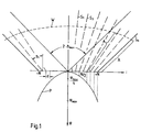
- the 2N + 1 converters are controlled on the basis with transmission signals that are mutually corresponding to phase shifts according to dotted ordinate values from converter location i to parabola P are delayed.
- the slope of the parabola P depends on the opening angle 2 ⁇ max of the sector. The smaller the opening angle 2 ⁇ max is chosen, the smaller the slope.
- the value ⁇ max is larger the larger ⁇ max .
- the slope of the parabola increases 2 ⁇ max for larger opening angles. With larger ordinate values, their focal point lies on the ⁇ axis.
- the spokes S1, S2, ..., S N intersect at one point.
- the sound waves spread from respective transducer location in the direction of the spoke S and after a time reaches the same distances A on the spokes S.
- Their wavefront W is perpendicular to the spokes S.
- the wavefront of a radiated "wave packet" is practically parallel to the base, its curvature increases with greater distances and acts in the far field as if a point-shaped transducer had radiated the pulse wave packet.
- phase values ⁇ i are determined as a function of the opening angle 2 ⁇ max of the sector, the base length, the mean wavelength of the sound waves and the transducer location.
- residual phase values ⁇ are determined from the phase values ⁇ i . Multiples of 2 ⁇ or 360 ° are subtracted from the phase values ⁇ i and combined to form a residual phase value ⁇ if they lie within a predetermined interval.
- the transmission signals are applied with the residual phase values ⁇ .
- the frequency of the sound waves is 100 kHz
- the pulse duration is 100 ms.
- the natural opening angle of the base is 0.4 ° due to its dimensions.
- Table 1 shows the reduced phase values ⁇ * i for each converter i, which are each grouped into residual phase values ⁇ in groups 1 to 20.
- the residual phase values ⁇ are reduced phase values ⁇ * i which lie within a predeterminable interval.
- the converters i belonging to a group 1, 2,..., 20 are electrically connected in the base and subjected to transmission signals, the residual phase values ⁇ of which are given in Table 2 below.
- the residual phase values ⁇ are mean values of the reduced phase values ⁇ * i of Table 1, their scatter ⁇ is given in Table 2.
- each group comprises 10 transducers, only group 1 comprises 11 transducers.
- FIG. 2 shows such a sonar system as a block diagram.
- 201 transducers are arranged equidistantly at a distance d on a flat base 1000 and numbered symmetrically to the base center.
- the 201 converters are interconnected on the basis of 1000 according to Table 1 to groups 1 to 20.
- the residual phase values for an opening angle ph are taken from Table 2.
- the corresponding residual phase values ⁇ are realized by twenty phase rotators 200, in which the residual phase values ⁇ are noted. Signal sequences from a signal generator 210 are applied to them. These signal sequences are, for example 100 kHz oscillations or FM sweeps from 90 kHz to 110 kHz during a specifiable pulse duration.
- the phase rotators 200 are connected by a control unit 220 to twenty power amplifiers 300, which are connected to groups 1 to 20 of the converters on the base 1000 via twenty cable connections 400.
- the control unit 220 controls a switch network with which, when the opening angle is increased from 10 ° to 20 ° or 30 °, corresponding phase rotators with the same residual phase values ⁇ are connected.
- the phase rotators 200 can be implemented in the same way by means of value tables in the form of ROMs (read-only memories) and microprocessors, in which the phase shift of the signal sequences takes place by multiplying complex numbers.
- the residual phase values are stored in the ROMs as a complex number.
- the remaining phase values can be stored again reduced by modulo 2 ⁇ .
- the multiplier is implemented by microprocessors.
- signal sequences are provided as complex numbers in digital form.
- the control part 220 ensures the correct transmission process by program.
- the power amplifiers 300 and cable connections 400 are retained in the same form.
Landscapes
- Physics & Mathematics (AREA)
- Engineering & Computer Science (AREA)
- Acoustics & Sound (AREA)
- Multimedia (AREA)
- Measurement Of Velocity Or Position Using Acoustic Or Ultrasonic Waves (AREA)
Claims (9)
- Montage pour l'émission impulsionnelle d'ondes acoustiques provenant d'une multiplicité (2N+1) de transducteurs électroacoustiques d'une base plane (1000) dans un secteur possédant un angle d'ouverture (2ϑmax) pouvant être prédéterminé, qui est supérieur à l'angle d'ouverture lors de la commande en phase des transducteurs, comportant des réseaux produisant un retard de phase et disposés en amont d'amplificateurs de puissance (300), pour leurs signaux d'émission, les retards étant déterminés par une fonction de conique tangente à la base et dont l'axe de symétrie est la ligne sommitale du secteur, caractérisé par le fait qu'à partir de l'angle d'ouverture (2ϑmax), une valeur de phase maximale (φmax) pour le transducteur situé le plus à l'extérieur est choisie égale à la moitié de la longueur de base (2N.d), rapportée à la longueur d'onde moyenne (λ) des ondes acoustiques, multipliée par π fois le demi-angle d'ouverture (ϑmax) ou le sinus du demi-angle d'ouverture (ϑmax), que les valeurs de phase (φi) pour les transducteurs sont formées de manière à augmenter de façon quadratique depuis le centre de la base (1000) en direction de l'extérieur, conformément à une parabole en tant que fonction de conique et que le foyer de la parabole correspond à 1/4 de la valeur de phase maximale (φmax), et qu'après une réduction, de multiples de 2π, des valeurs de phase pour les différents transducteurs, les valeurs de phase réduite (φi*), qui sont situées dans un intervalle pouvant être prédéterminé, sont réunies pour former une valeur de phase résiduelle (φ), les valeurs de phase résiduelles (φ) étant des retards pour les signaux d'émission et pouvant être appliquées aux signaux d'émission, en tant que déphasage (circuits de rotation de phase 200).
- Montage selon la revendication 1, caractérisé en ce que les transducteurs, dont les valeurs de phase réduites (φi*) sont situées dans l'intervalle, sont rassemblés électriquement au niveau de la base (1000) pour former un groupe.
- Montage selon la revendication 1 ou 2, caractérisé en ce que l'intervalle peut être prédéterminé en fonction d'un affaiblissement désiré de niveau secondaire à l'extérieur du secteur.
- Montage selon la revendication 3, caractérisé en ce que le nombre des amplificateurs de puissance (300) peut être déterminé par l'intervalle prédéterminé.
- Montage selon l'une des revendications 1 à 4, caractérisé en ce que l'intervalle peut être tiré d'une dispersion admissible (σ) autour de la valeur de phase résiduelle respective (φ).
- Montage selon l'une des revendications 1 à 5, caractérisé en ce que pour accroître de façon supplémentaire l'angle d'ouverture de multiples entiers d'un très petit angle d'ouverture (ϑ), on prévoit les mêmes valeurs de phase résiduelle (φ) de façon multiple et on peut les appliquer en tant que déphasages pour les signaux d'émission (circuits de rotation de phase 200).
- Montage selon l'une des revendications 1 à 5, caractérisé en ce qu'il est prévu, comme réseaux produisant un retard de phase, des circuits de rotation de phase (200) servant à réaliser un déphasage correspondant aux valeurs de phase résiduelles (φ) entre le générateur de signaux (210) et l'amplificateur de puissance (300) pour les transducteurs.
- Montage selon les revendications 6 et 7, caractérisé en ce que des multiples des circuits de rotation de phase (200) produisant le même déphasage peuvent être raccordés en supplément.
- Montage selon l'une des revendications 1 à 6, caractérisé en ce que les valeurs de phase résiduelles (φ) peuvent être mémorisées dans un tableau de valeurs, qu'autant de signaux signaux sinusoïdaux qu'il y a de valeurs de phase résiduelles (φ) peuvent être préparés dans un générateur de signaux (210) et que les signaux sinusoïdaux peuvent être appliqués, en étant déphasés par multiplication avec la valeur de phase résiduelle (φ) tirée du tableau de valeurs, à des amplificateurs de puissance (300) pour les transducteurs.
Applications Claiming Priority (2)
| Application Number | Priority Date | Filing Date | Title |
|---|---|---|---|
| DE4024353 | 1990-08-01 | ||
| DE19904024353 DE4024353A1 (de) | 1990-08-01 | 1990-08-01 | Schaltanordnung zum impulsfoermigen abstrahlen von schallwellen |
Publications (3)
| Publication Number | Publication Date |
|---|---|
| EP0469242A2 EP0469242A2 (fr) | 1992-02-05 |
| EP0469242A3 EP0469242A3 (en) | 1992-08-26 |
| EP0469242B1 true EP0469242B1 (fr) | 1995-07-26 |
Family
ID=6411407
Family Applications (1)
| Application Number | Title | Priority Date | Filing Date |
|---|---|---|---|
| EP19910106752 Expired - Lifetime EP0469242B1 (fr) | 1990-08-01 | 1991-04-26 | Circuit pour l'émission à impulsion des ondes sonores |
Country Status (2)
| Country | Link |
|---|---|
| EP (1) | EP0469242B1 (fr) |
| DE (1) | DE4024353A1 (fr) |
Families Citing this family (1)
| Publication number | Priority date | Publication date | Assignee | Title |
|---|---|---|---|---|
| FR2697346B1 (fr) * | 1992-10-26 | 1995-01-27 | Univ Paris Curie | Dispositif de sondage ultrasonore à commande numérique de phase. |
Family Cites Families (11)
| Publication number | Priority date | Publication date | Assignee | Title |
|---|---|---|---|---|
| DE2064588C3 (de) * | 1970-12-30 | 1978-09-21 | Fried. Krupp Gmbh, 4300 Essen | Schaltanordnung zum Abstrahlen von Sendeenergie in einen vorgegebenen Sektor |
| JPS565536B2 (fr) * | 1973-05-21 | 1981-02-05 | ||
| FR2292978A1 (fr) * | 1974-11-28 | 1976-06-25 | Anvar | Perfectionnements aux dispositifs de sondage par ultra-sons |
| FR2317666A1 (fr) * | 1975-07-07 | 1977-02-04 | Inst Francais Du Petrole | Dispositif emetteur-recepteur d'ondes acoustiques |
| CH608103A5 (fr) * | 1975-12-01 | 1978-12-15 | Hoffmann La Roche | |
| US4180792A (en) * | 1978-03-09 | 1979-12-25 | General Electric Company | Transmit-receive transducer array and ultrasonic imaging system |
| DE3010210A1 (de) * | 1980-03-17 | 1981-09-24 | Siemens AG, 1000 Berlin und 8000 München | Ultraschall-array |
| DE3151028A1 (de) * | 1981-12-23 | 1983-07-28 | Fried. Krupp Gmbh, 4300 Essen | Akustische unterwasserantenne |
| US4454597A (en) * | 1982-05-03 | 1984-06-12 | The United States Of America As Represented By The Secretary Of The Navy | Conformal array compensating beamformer |
| FR2542884B1 (fr) * | 1983-03-18 | 1986-12-26 | Cgr Ultrasonic | Procede d'imagerie par ultrasons a partir d'un alignement d'elements transducteurs |
| JPS6052784A (ja) * | 1983-08-31 | 1985-03-26 | Yokogawa Medical Syst Ltd | 方位角適応型フエ−ズド・アレイ・ソ−ナ− |
-
1990
- 1990-08-01 DE DE19904024353 patent/DE4024353A1/de active Granted
-
1991
- 1991-04-26 EP EP19910106752 patent/EP0469242B1/fr not_active Expired - Lifetime
Also Published As
| Publication number | Publication date |
|---|---|
| DE4024353A1 (de) | 1992-02-13 |
| DE4024353C2 (fr) | 1993-01-21 |
| EP0469242A3 (en) | 1992-08-26 |
| EP0469242A2 (fr) | 1992-02-05 |
Similar Documents
| Publication | Publication Date | Title |
|---|---|---|
| DE19648203C2 (de) | Mehrstrahliges Kraftfahrzeug-Radarsystem | |
| DE112008000513B4 (de) | Elektronisch abtastendes Radarsystem | |
| DE69715297T2 (de) | Logarithmische spiralförmige Wandleranordnung | |
| EP0028969B1 (fr) | Circuit de formation d'un faisceau somme et différence à lobe latéral omnidirectionel pour un réseau d'antenne à éléments multiples et procédé de détermination des poids de celui-ci | |
| DE3689143T2 (de) | Ultraschallabbildungssystem mit einer dynamisch fokussierten phasengesteuerten linearen Wandleranordnung. | |
| DE69720483T2 (de) | Zweidimensionale wandleranordnung mit strahlformer | |
| DE2265692C2 (fr) | ||
| DE69020505T2 (de) | 2-Dimensionales, mit phasengesteuertem Array ausgestattetes Ultraschallabbildungssystem mit verteilter Phasierung. | |
| DE3586294T2 (de) | Mit phasengesteuerter wandleranordnung ausgestattetes akustisches abbildungssystem. | |
| DE2604048C2 (de) | Strahlergruppe, deren Strahler in zu einer Symmetrieachse koaxialen, axial beabstandeten Ringen angeordnet sind | |
| DE2621211A1 (de) | Mit amplitudenmodulation arbeitende strahlschwenkanordnung | |
| DE1591056B1 (de) | Impulsradargeraet mit elevationsgestaffelten Antennenstrahlern zur phasengesteuerten Strahlschwenkung | |
| DE1541462C3 (de) | Richtantennensystem für Radargeräte | |
| DE69314412T2 (de) | Antenne mit Nebenkeulenunterdrückung | |
| DE3151028C2 (fr) | ||
| DE3854303T2 (de) | Ultraschall-diagnosegerät. | |
| EP0469242B1 (fr) | Circuit pour l'émission à impulsion des ondes sonores | |
| DE19648327B4 (de) | Verfahren zur Richtstrahlbildung in Peilanlagen und Vorrichtung zur Durchführung des Verfahrens | |
| DE3807114A1 (de) | Richtantenne mit einer vielzahl von wandlern, insbesondere fuer sonaranwendungen | |
| DE69421313T2 (de) | Verfahren zur Strahlungskeulenkompression von Radarantennendiagrammen | |
| EP0450191B1 (fr) | Arrangement de transducteurs | |
| DE10153443C1 (de) | Verfahren zur passiven Ortung von schallabstrahlenden Zielen | |
| EP0433492A1 (fr) | Dispositif ultrasonore pour la réduction virtuelle de la division arrangée d'un alignement de transducteur raccordé | |
| EP0263314B1 (fr) | Disposition de transducteurs | |
| DE1766059A1 (de) | Verteilersystem fuer Mikrowellengeraete |
Legal Events
| Date | Code | Title | Description |
|---|---|---|---|
| PUAI | Public reference made under article 153(3) epc to a published international application that has entered the european phase |
Free format text: ORIGINAL CODE: 0009012 |
|
| AK | Designated contracting states |
Kind code of ref document: A2 Designated state(s): FR GB IT NL SE |
|
| RAP1 | Party data changed (applicant data changed or rights of an application transferred) |
Owner name: ATLAS ELEKTRONIK GMBH |
|
| PUAL | Search report despatched |
Free format text: ORIGINAL CODE: 0009013 |
|
| AK | Designated contracting states |
Kind code of ref document: A3 Designated state(s): FR GB IT NL SE |
|
| 17P | Request for examination filed |
Effective date: 19920819 |
|
| 17Q | First examination report despatched |
Effective date: 19940330 |
|
| RAP1 | Party data changed (applicant data changed or rights of an application transferred) |
Owner name: STN ATLAS ELEKTRONIK GMBH |
|
| GRAA | (expected) grant |
Free format text: ORIGINAL CODE: 0009210 |
|
| AK | Designated contracting states |
Kind code of ref document: B1 Designated state(s): FR GB IT NL SE |
|
| PG25 | Lapsed in a contracting state [announced via postgrant information from national office to epo] |
Ref country code: IT Free format text: LAPSE BECAUSE OF FAILURE TO SUBMIT A TRANSLATION OF THE DESCRIPTION OR TO PAY THE FEE WITHIN THE PRESCRIBED TIME-LIMIT;WARNING: LAPSES OF ITALIAN PATENTS WITH EFFECTIVE DATE BEFORE 2007 MAY HAVE OCCURRED AT ANY TIME BEFORE 2007. THE CORRECT EFFECTIVE DATE MAY BE DIFFERENT FROM THE ONE RECORDED. Effective date: 19950726 Ref country code: NL Free format text: LAPSE BECAUSE OF FAILURE TO SUBMIT A TRANSLATION OF THE DESCRIPTION OR TO PAY THE FEE WITHIN THE PRESCRIBED TIME-LIMIT Effective date: 19950726 |
|
| ET | Fr: translation filed | ||
| GBT | Gb: translation of ep patent filed (gb section 77(6)(a)/1977) |
Effective date: 19950814 |
|
| PG25 | Lapsed in a contracting state [announced via postgrant information from national office to epo] |
Ref country code: SE Effective date: 19951026 |
|
| NLV1 | Nl: lapsed or annulled due to failure to fulfill the requirements of art. 29p and 29m of the patents act | ||
| PLBE | No opposition filed within time limit |
Free format text: ORIGINAL CODE: 0009261 |
|
| STAA | Information on the status of an ep patent application or granted ep patent |
Free format text: STATUS: NO OPPOSITION FILED WITHIN TIME LIMIT |
|
| 26N | No opposition filed | ||
| PGFP | Annual fee paid to national office [announced via postgrant information from national office to epo] |
Ref country code: GB Payment date: 19980312 Year of fee payment: 8 |
|
| PGFP | Annual fee paid to national office [announced via postgrant information from national office to epo] |
Ref country code: FR Payment date: 19980317 Year of fee payment: 8 |
|
| PG25 | Lapsed in a contracting state [announced via postgrant information from national office to epo] |
Ref country code: GB Free format text: LAPSE BECAUSE OF NON-PAYMENT OF DUE FEES Effective date: 19990426 |
|
| GBPC | Gb: european patent ceased through non-payment of renewal fee |
Effective date: 19990426 |
|
| PG25 | Lapsed in a contracting state [announced via postgrant information from national office to epo] |
Ref country code: FR Free format text: LAPSE BECAUSE OF NON-PAYMENT OF DUE FEES Effective date: 19991231 |
|
| REG | Reference to a national code |
Ref country code: FR Ref legal event code: ST |