EP0469376A1 - Zweiwalzenmaschine, insbesondere Rollenpresse - Google Patents
Zweiwalzenmaschine, insbesondere Rollenpresse Download PDFInfo
- Publication number
- EP0469376A1 EP0469376A1 EP91111822A EP91111822A EP0469376A1 EP 0469376 A1 EP0469376 A1 EP 0469376A1 EP 91111822 A EP91111822 A EP 91111822A EP 91111822 A EP91111822 A EP 91111822A EP 0469376 A1 EP0469376 A1 EP 0469376A1
- Authority
- EP
- European Patent Office
- Prior art keywords
- lever
- arms
- rollers
- torsion shaft
- roller
- Prior art date
- Legal status (The legal status is an assumption and is not a legal conclusion. Google has not performed a legal analysis and makes no representation as to the accuracy of the status listed.)
- Granted
Links
- 230000005540 biological transmission Effects 0.000 description 2
Images
Classifications
-
- B—PERFORMING OPERATIONS; TRANSPORTING
- B02—CRUSHING, PULVERISING, OR DISINTEGRATING; PREPARATORY TREATMENT OF GRAIN FOR MILLING
- B02C—CRUSHING, PULVERISING, OR DISINTEGRATING IN GENERAL; MILLING GRAIN
- B02C4/00—Crushing or disintegrating by roller mills
- B02C4/28—Details
- B02C4/42—Driving mechanisms; Roller speed control
- B02C4/426—Torque counterbalancing mechanisms
Definitions
- the invention relates to a two-roll machine, in particular a roller press, consisting of two rolls which are rotatably mounted in a housing and are driven in opposite directions, with gears plugged onto the drive pins of the rolls, which are provided with torque supports for receiving the reaction moments, which are designed as lever plates with two arms and on the one hand with the gearboxes are firmly connected and, on the other hand, are rotatably connected to a torsion shaft via lever arms and levers.
- a roller press consisting of two rolls which are rotatably mounted in a housing and are driven in opposite directions, with gears plugged onto the drive pins of the rolls, which are provided with torque supports for receiving the reaction moments, which are designed as lever plates with two arms and on the one hand with the gearboxes are firmly connected and, on the other hand, are rotatably connected to a torsion shaft via lever arms and levers.
- the gearboxes attached to the drive pins of the rollers are provided with torque supports to absorb the reaction moments, which consist of lever plates with two diametrically opposed arms of the same length, each of which is firmly connected to the gearbox .
- the above-mentioned lever plates are also provided with two equally long, diametrically opposed arms and, on the one hand, are firmly connected to the gears and, on the other hand, are rotatable via a lever and lever arms with a torsion shaft connected.
- This configuration and arrangement of the torque supports ensures that the gearbox is supported without lateral force when the two-roll machine is in operation, but only one gearbox can be arranged on one side of the two-roll machine for reasons of space. This in turn is associated with an increased space requirement.
- the object of the invention is a further improvement of the two-roll machines mentioned at the outset, in particular in terms of design and in their mode of operation.
- lever plate arms rotatably connected to the torsion shaft via linkages and lever arms are of unequal length. Due to this unequal length of the lever plate arms, both gears for the rollers can very advantageously be arranged on one side of the two-roller machine, which not only achieves a considerably more compact design of the two-roller machine overall, but also without obstructing the evasive movement of the idler roller relative to the fixed roller both the roller bearings and the machine frame are kept free of lateral forces.
- the lever arms connected to the torsion shaft are of different lengths. Due to this unequal length of the lever arms, which are connected to the torsion shaft, the bearing of the shaft can be relieved partially or even completely of the weight of the transmission and the motor.
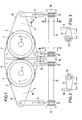
- the two-roll machine consists of two, in a housing, not shown in the drawing, rotatably mounted, counter-rotating rollers (1 and 2) with gears (5 and 6) attached to the drive pins (3 and 4) of the rollers ).
- the gearboxes (5 and 6) are provided with torque supports to absorb the reaction moments, which are designed with two arms as lever plates (7 and 8) and are firmly connected on the one hand to the gearboxes (5 and 6) and on the other hand via linkages (9, 10) and lever arms (11, 12) are rotatably connected to a torsion shaft (13).
- the linkages (9, 10) and lever arms (11, 12) engaging on the lever plate (7) are identical in design to the linkages and lever arms engaging on the lever plate (8), they have been given the same reference numbers in the drawing for the sake of simplicity Mistake.
- the torsion shaft (13) shown on the right in the drawing is rotatably supported in the machine frame (15) independently of the torsion shaft (14) shown on the left in the drawing.
- the lever plate arms (16 and 17) which are rotatably connected to the respective torsion shaft (13 and 14) via the linkages (9, 10) and lever arms (11, 12) are of different lengths.
Landscapes
- Engineering & Computer Science (AREA)
- Food Science & Technology (AREA)
- Rolls And Other Rotary Bodies (AREA)
- Press Drives And Press Lines (AREA)
- Paper (AREA)
- Yarns And Mechanical Finishing Of Yarns Or Ropes (AREA)
- Crushing And Grinding (AREA)
Abstract
Description
- Die Erfindung bezieht sich auf eine Zweiwalzenmaschine, insbesondere Rollenpresse, bestehend aus zwei in einem Gehäuse drehbar gelagerten, gegenläufig angetriebenen Walzen mit auf den Antriebszapfen der Walzen aufgesteckten Getrieben, die zur Aufnahme der Reaktionsmomente mit Drehmomentenstützen versehen sind, die als Hebelplatten zweiarmig ausgebildet und einerseits mit den Getrieben fest ver bunden sind und andererseits über Hebelarme und Hebel mit einer Torsionswelle drehbeweglich verbunden sind.
- Bei einer Zweiwalzenmaschine gemäß der deutschen Patentanmeldung P 39 01 060.0 sind die auf den Antriebszapfen der Walzen aufgesteckten Getriebe zur Aufnahme der Reaktionsmomente mit Drehmomentenstützen versehen, die aus Hebelplatten mit zwei diametral gegenüberliegenden, gleich lang ausgebildeten Armen bestehen, welche jeweils mit dem Getriebe fest verbunden sind.
- Gemäß der aus dem KHD Humboldt Wedag-Prospekt 11-304d bekannten Rollenpresse HW-RP sind diese oben erwähnten Hebelplatten ebenfalls mit zwei gleich langen, einander diametral gegenüberliegenden Armen versehen und einerseits mit den Getrieben fest verbunden und andererseits über Hebel und Hebelarme mit einer Torsionswelle drehbeweglich verbunden. Durch diese Ausbildung und Anordnung der Drehmomentenstützen wird bei einem Betrieb der Zweiwalzenmaschine eine querkraftfreie Abstützung der Getriebe erreicht, jedoch kann aus Platzgründen jeweils nur ein Getriebe an einer Seite der Zweiwalzenmaschine angeordnet werden. Dies ist wiederum mit einem erhöhten Platzbedarf verbunden.
- Die Aufgabe der Erfindung besteht in einer weitergehenden Verbesserung der eingangs angeführten Zweiwalzenmaschinen, insbesondere in konstruktiver Hinsicht und in ihrer Wirkungsweise.
- Diese Aufgabe wird dadurch gelöst, daß die über Gestänge und Hebelarme mit der Torsionswelle drehbeweglich verbundenen Hebelplattenarme ungleich lang ausgebildet sind. Durch diese ungleich lange Ausbildung der Hebelplattenarme können sehr vorteilhaft beide Getriebe für die Walzen auf einer Seite an der Zweiwalzenmaschine nebeneinander angeordnet werden, wodurch nicht nur eine erheblich kompaktere Bauweise der Zweiwalzenmaschine insgesamt erreicht wird, sondern wodurch auch ohne Behinderung der Ausweichbewegung der Loswalze gegenüber der Festwalze sowohl die Walzenlager als auch der Maschinenrahmen von Querkräften freigehalten wird.
- Gemäß einer weiteren vorteilhaften Ausgestaltung der Erfindung sind die mit der Torsionswelle in Verbindung stehenden Hebelarme ungleich lang ausgebildet. Durch diese ungleich lange Ausbildung der Hebelarme, die mit der Torsionswelle in Verbindung stehen, kann sehr vorteilhaft das Lager der Welle vom Gewicht des Getriebes und des Motors teilweise oder sogar vollständig entlastet werden.
- Weitere Einzelheiten, Merkmale und Vorteile der Erfindung werden nachfolgend anhand eines in Zeichnungsfiguren schematisch näher dargestellten Ausführungsbeispiels erläutert.
- Es zeigt:
- Fig. 1 eine mit ungleich langen Hebelplattenarmen ausgebildete Drehmomentenstützenanordnung gemäß der Erfindung bei einer Walzenpresse in Seitenansicht;
- Fig. 2 einen Schnitt nach der Linie 11-11 in Fig. 1;
- Fig. 3 einen Schnitt nach der Linie 111-111 in Fig. 1;
- Wie Fig. 1 zeigt, besteht die Zweiwalzenmaschine aus zwei, in einem in der Zeichnung nicht näher dargestellten Gehäuse, drehbar gelagerten, gegenläufig angetriebenen Walzen (1 und 2) mit auf den Antriebszapfen (3 und 4) der Walzen aufgesteckten Getrieben (5 und 6). Die Getriebe (5 und 6) sind zur Aufnahme der Reaktionsmomente mit Drehmomentenstützen versehen, die als Hebelplatten (7 und 8) zweiarmig ausgebildet und einerseits mit den Getrieben (5 und 6) fest verbunden sind und andererseits über Gestänge (9, 10) und Hebelarme (11, 12) mit einer Torsionswelle (13) drehbeweglich verbunden sind. Da die an der Hebelplatte (7) angreifenden Gestänge (9, 10) und Hebelarme (11, 12) identisch gleich ausgebildet sind, wie die an der Hebelplatte (8) angreifenden Gestänge und Hebelarme, wurden sie der einfachheithalber in der Zeichnung mit denselben Bezugsziffern versehen. Die in der Zeichnung auf der rechten Seite dargestellte Torsionswelle (13) ist jedoch unabhängig von der in der Zeichnung auf der linken Seite dargestellten Torsionswelle (14) im Maschinenrahmen (15) drehbar gelagert. Gemäß der Erfindung sind die über die Gestänge (9, 10) und Hebelarme (11, 12) mit der jeweiligen Torsionswelle (13 bzw. 14) drehbeweglich verbundenen Hebelplattenarme (16 und 17) ungleich lang ausgebildet. Diese ungleichlange Ausbildung der als Drehmomentenstützen dienenden Hebelplattenarme (16, 17) ermöglicht sehr vorteilhaft eine äußerst platzsparende Anordnung der Aufsteckgetriebe (5 und 6) an einer Seite der Zweiwalzenmaschine und dadurch eine sehr kompakte, raumsparende Bauweise der Zweiwalzenmaschine insgesamt. Ferner sind hierbei, wie insbesondere die Figuren 2 und 3 zeigen, die mit der Torsionswelle (13 bzw. 14) in Verbindung stehenden Hebelarme (11 und 12) ungleich lang ausgebildet, und zwar weist der Hebelarm (11), der über das Gestänge (9) mit dem äußeren länger ausgebildeten Hebelplattenarm (16) verbunden ist, eine kürzere Hebelarmlänge (r) auf als der Hebelarm (12) mit der Hebelarmlänge (R), welcher über das Gestänge (10) mit den kurz ausgebildeten Hebelplattenarm (17) gelenkig verbunden ist. Durch diese ungleichlange Ausbildung der Hebelarme (11 und 12) kann sehr vorteilhaft das Lager der Welle vom Eigengewicht des Getriebes und des Antriebsmotors teilweise oder vollständig entlastet werden. Dabei wird durch die im Betrieb der Zweiwalzenmaschine auftretenden Reaktionsmomente (Pfeil 18) das Gestänge (9) auf Druck und das Gestänge (10) auf Zug beansprucht. Durch diese erfindungsgemäße ungleichlange Ausbildung der Hebelplattenarme (16 und 17), die zur Aufnahme der von den Steckgetrieben (5 und 6) ausgehenden Reaktionsmomente über die Gestänge (9, 10) und Hebelarme (11 und 12) mit der Torsionswelle (13 bzw. 14) drehbeweglich verbunden sind, wird nicht nur eine in ihrem konstruktiven Aufbau sehr einfache und besonders platzsparende Drehmomentenabstützung erreicht, sondern auch eine stets funktionstüchtige querkraftfreie Arbeitsweise gewährleistet. Auch können diese erfindungsgemäß ausgebildeten Drehmomentenstützen bei bereits bestehenden Zweiwalzenmaschinen, insbesondere bei Rollenpressen, noch nachträglich sehr leicht angebracht werden.
Claims (2)
Applications Claiming Priority (2)
| Application Number | Priority Date | Filing Date | Title |
|---|---|---|---|
| DE4024109 | 1990-07-30 | ||
| DE4024109A DE4024109A1 (de) | 1990-07-30 | 1990-07-30 | Zweiwalzenmaschine, insbesondere rollenpresse |
Publications (2)
| Publication Number | Publication Date |
|---|---|
| EP0469376A1 true EP0469376A1 (de) | 1992-02-05 |
| EP0469376B1 EP0469376B1 (de) | 1994-08-31 |
Family
ID=6411270
Family Applications (1)
| Application Number | Title | Priority Date | Filing Date |
|---|---|---|---|
| EP91111822A Expired - Lifetime EP0469376B1 (de) | 1990-07-30 | 1991-07-16 | Zweiwalzenmaschine, insbesondere Rollenpresse |
Country Status (5)
| Country | Link |
|---|---|
| US (1) | US5192030A (de) |
| EP (1) | EP0469376B1 (de) |
| AT (1) | ATE110589T1 (de) |
| DE (2) | DE4024109A1 (de) |
| DK (1) | DK0469376T3 (de) |
Cited By (5)
| Publication number | Priority date | Publication date | Assignee | Title |
|---|---|---|---|---|
| EP0667186A1 (de) * | 1994-02-14 | 1995-08-16 | Krupp Polysius Ag | Walzenmühle |
| EP0775525A1 (de) * | 1995-11-21 | 1997-05-28 | A. Friedr. Flender Ag | Drehmomentabstützung |
| DE10018271A1 (de) * | 2000-04-13 | 2001-10-18 | Kloeckner Humboldt Wedag | Zweiwalzenmaschine mit Schwenkrahmen |
| CN103691510A (zh) * | 2013-12-05 | 2014-04-02 | 铜陵晟王铁路装备股份有限公司 | 重力加载型高压对辊挤压磨机 |
| CN106269056A (zh) * | 2015-06-02 | 2017-01-04 | 中国有色(沈阳)冶金机械有限公司 | 一种高压辊磨机用扭矩支撑装置 |
Families Citing this family (12)
| Publication number | Priority date | Publication date | Assignee | Title |
|---|---|---|---|---|
| GB2252517A (en) * | 1991-02-07 | 1992-08-12 | Smidth & Co As F L | Roller press with torque counter balancing |
| SK283611B6 (sk) * | 1997-04-15 | 2003-10-07 | Fcb | Zdokonalenie drviča s prstencovitým bubnom a s drviacim valcom |
| DE102007059073A1 (de) * | 2007-12-07 | 2009-06-10 | Khd Humboldt Wedag Gmbh | Rollenpresse mit symmetrischer Walzenzentrierung |
| SE532690C2 (sv) * | 2008-06-30 | 2010-03-16 | Metso Brasil Ind E Com Ltda | Lagerarrangemang |
| US8632028B2 (en) | 2010-09-02 | 2014-01-21 | Flsmidth A/S | Device for the comminution of material |
| CN102228848B (zh) * | 2011-06-29 | 2014-04-16 | 成都利君实业股份有限公司 | 一种辊压机(高压辊磨机)用独立扭矩支承系统 |
| DE102015223694A1 (de) * | 2015-11-30 | 2017-06-01 | Takraf Gmbh | Getriebehalter für eine Rollenpresse und Verfahren zum Ausbau des Getriebes einer Rollenpresse |
| DE102016211276B4 (de) | 2016-06-23 | 2018-03-15 | Takraf Gmbh | Zerkleinerungsvorrichtung zur druckbehandlung eines körnigen aufgabeguts |
| ES2831032T3 (es) * | 2018-03-08 | 2021-06-07 | Flender Gmbh | Dispositivo de soporte para un par de giro de engranajes y aplicación industrial |
| EP3965938A4 (de) * | 2019-05-09 | 2023-08-23 | Metso Outotec USA Inc. | Zerkleinerungsvorrichtung |
| SE543582C2 (en) * | 2019-06-25 | 2021-04-06 | Valmet Oy | A torque reaction arrangement for pulp washers and a pulp washer including the arrangement |
| DE102020103823B3 (de) * | 2020-02-13 | 2021-01-21 | Matthews International GmbH | Drehmomentstütze zum Abfangen von Antriebsmomenten und Walzenanordnung mit einer Drehmomentstütze |
Citations (3)
| Publication number | Priority date | Publication date | Assignee | Title |
|---|---|---|---|---|
| AT347212B (de) * | 1975-04-03 | 1978-12-11 | Voest Ag | Walzenbrecher |
| EP0280897A2 (de) * | 1987-03-05 | 1988-09-07 | Krupp Polysius Ag | Walzenmühle |
| DE3723605A1 (de) * | 1987-07-17 | 1989-01-26 | Kloeckner Humboldt Deutz Ag | Zweiwalzenmaschine, wie z. b. walzenpresse |
Family Cites Families (2)
| Publication number | Priority date | Publication date | Assignee | Title |
|---|---|---|---|---|
| NL101060C (de) * | 1952-03-14 | |||
| US4519188A (en) * | 1984-03-02 | 1985-05-28 | Sperry Corporation | Linkage for equalizing conditioning roll pressure |
-
1990
- 1990-07-30 DE DE4024109A patent/DE4024109A1/de not_active Withdrawn
-
1991
- 1991-07-16 EP EP91111822A patent/EP0469376B1/de not_active Expired - Lifetime
- 1991-07-16 AT AT91111822T patent/ATE110589T1/de not_active IP Right Cessation
- 1991-07-16 DK DK91111822.2T patent/DK0469376T3/da active
- 1991-07-16 DE DE59102725T patent/DE59102725D1/de not_active Expired - Fee Related
- 1991-07-30 US US07/737,681 patent/US5192030A/en not_active Expired - Lifetime
Patent Citations (3)
| Publication number | Priority date | Publication date | Assignee | Title |
|---|---|---|---|---|
| AT347212B (de) * | 1975-04-03 | 1978-12-11 | Voest Ag | Walzenbrecher |
| EP0280897A2 (de) * | 1987-03-05 | 1988-09-07 | Krupp Polysius Ag | Walzenmühle |
| DE3723605A1 (de) * | 1987-07-17 | 1989-01-26 | Kloeckner Humboldt Deutz Ag | Zweiwalzenmaschine, wie z. b. walzenpresse |
Cited By (7)
| Publication number | Priority date | Publication date | Assignee | Title |
|---|---|---|---|---|
| EP0667186A1 (de) * | 1994-02-14 | 1995-08-16 | Krupp Polysius Ag | Walzenmühle |
| EP0775525A1 (de) * | 1995-11-21 | 1997-05-28 | A. Friedr. Flender Ag | Drehmomentabstützung |
| DE10018271A1 (de) * | 2000-04-13 | 2001-10-18 | Kloeckner Humboldt Wedag | Zweiwalzenmaschine mit Schwenkrahmen |
| CN103691510A (zh) * | 2013-12-05 | 2014-04-02 | 铜陵晟王铁路装备股份有限公司 | 重力加载型高压对辊挤压磨机 |
| CN103691510B (zh) * | 2013-12-05 | 2016-05-11 | 铜陵迈臣机电科技有限责任公司 | 重力加载型高压对辊挤压磨机 |
| CN106269056A (zh) * | 2015-06-02 | 2017-01-04 | 中国有色(沈阳)冶金机械有限公司 | 一种高压辊磨机用扭矩支撑装置 |
| CN106269056B (zh) * | 2015-06-02 | 2019-01-22 | 中国有色(沈阳)冶金机械有限公司 | 一种高压辊磨机用扭矩支撑装置 |
Also Published As
| Publication number | Publication date |
|---|---|
| DK0469376T3 (da) | 1994-10-03 |
| ATE110589T1 (de) | 1994-09-15 |
| DE4024109A1 (de) | 1992-02-06 |
| US5192030A (en) | 1993-03-09 |
| DE59102725D1 (de) | 1994-10-06 |
| EP0469376B1 (de) | 1994-08-31 |
Similar Documents
| Publication | Publication Date | Title |
|---|---|---|
| EP0469376B1 (de) | Zweiwalzenmaschine, insbesondere Rollenpresse | |
| DE2901208C2 (de) | Verstellbarer Sitz, insbesondere Fahrzeugsitz | |
| DE2413200B2 (de) | Baggergreifer | |
| CH642303A5 (de) | Antrieb fuer rollenrotations-offsetdruckmaschine. | |
| DE2507677B2 (de) | Walze für ein walzwerk | |
| DE2345004C3 (de) | Antriebsvorrichtung für langsam umlaufende Wellen | |
| DE3901060A1 (de) | Zweiwalzenmaschine, insbesondere walzenbrecher | |
| DE102021213069B3 (de) | Antrieb für eine Lenkachse eines Flurförderzeugs, Lenkachse und Flurförderzeug | |
| DE3723605A1 (de) | Zweiwalzenmaschine, wie z. b. walzenpresse | |
| DE1752666B2 (de) | Blechplattenbiegemaschine | |
| CH687244A5 (de) | Vorrichtung zum Verfahren von zwei auf Schlitten befestigten Lagerboecken. | |
| EP0615841B1 (de) | Druckmaschine | |
| EP0775525B1 (de) | Drehmomentabstützung | |
| DE3639803C2 (de) | ||
| EP0734680A1 (de) | Presse für Reinigungsgeräte | |
| CH647720A5 (de) | Einrichtung zum andruecken und abheben einer papiertransportwelle an eine bzw. von einer schreibwalze einer schreibmaschine, eines druckers oder dergleichen. | |
| DE2326122B2 (de) | Maschine zum Entwickeln von Offset-Druckplatten | |
| EP1226372A1 (de) | Möbelantrieb | |
| DE2510935C2 (de) | Papierwagenrahmen fuer schreib- oder aehnliche bueromaschinen | |
| DE102005062034A1 (de) | Zahnstangen-Lenkgetriebe | |
| EP1818300A1 (de) | Querfalzeinrichtung eines Falzapparats einer Druckmaschine | |
| DE9312143U1 (de) | Rundballenpresse für landwirtschaftliche Erntegüter | |
| DE649677C (de) | Buchungsschreibmaschine mit Vorsteckeinrichtung | |
| DE2051127A1 (de) | Sitz, insbesondere Kraftfahrzeugsitz | |
| DE4103742A1 (de) | Einstellbare feuchtwerks- oder farbwerkswalze |
Legal Events
| Date | Code | Title | Description |
|---|---|---|---|
| PUAI | Public reference made under article 153(3) epc to a published international application that has entered the european phase |
Free format text: ORIGINAL CODE: 0009012 |
|
| AK | Designated contracting states |
Kind code of ref document: A1 Designated state(s): AT DE DK ES FR GB IT |
|
| 17P | Request for examination filed |
Effective date: 19920919 |
|
| 17Q | First examination report despatched |
Effective date: 19930603 |
|
| GRAA | (expected) grant |
Free format text: ORIGINAL CODE: 0009210 |
|
| AK | Designated contracting states |
Kind code of ref document: B1 Designated state(s): AT DE DK ES FR GB IT |
|
| PG25 | Lapsed in a contracting state [announced via postgrant information from national office to epo] |
Ref country code: GB Effective date: 19940831 Ref country code: ES Free format text: THE PATENT HAS BEEN ANNULLED BY A DECISION OF A NATIONAL AUTHORITY Effective date: 19940831 Ref country code: IT Free format text: LAPSE BECAUSE OF FAILURE TO SUBMIT A TRANSLATION OF THE DESCRIPTION OR TO PAY THE FEE WITHIN THE PRE;WARNING: LAPSES OF ITALIAN PATENTS WITH EFFECTIVE DATE BEFORE 2007 MAY HAVE OCCURRED AT ANY TIME BEFORE 2007. THE CORRECT EFFECTIVE DATE MAY BE DIFFERENT FROM THE ONE RECORDED.SCRIBED TIME-LIMIT Effective date: 19940831 |
|
| REF | Corresponds to: |
Ref document number: 110589 Country of ref document: AT Date of ref document: 19940915 Kind code of ref document: T |
|
| ET | Fr: translation filed | ||
| REG | Reference to a national code |
Ref country code: DK Ref legal event code: T3 |
|
| REF | Corresponds to: |
Ref document number: 59102725 Country of ref document: DE Date of ref document: 19941006 |
|
| GBV | Gb: ep patent (uk) treated as always having been void in accordance with gb section 77(7)/1977 [no translation filed] |
Effective date: 19940831 |
|
| PLBE | No opposition filed within time limit |
Free format text: ORIGINAL CODE: 0009261 |
|
| STAA | Information on the status of an ep patent application or granted ep patent |
Free format text: STATUS: NO OPPOSITION FILED WITHIN TIME LIMIT |
|
| PG25 | Lapsed in a contracting state [announced via postgrant information from national office to epo] |
Ref country code: AT Effective date: 19950716 |
|
| 26N | No opposition filed | ||
| PGFP | Annual fee paid to national office [announced via postgrant information from national office to epo] |
Ref country code: FR Payment date: 19970613 Year of fee payment: 7 |
|
| REG | Reference to a national code |
Ref country code: FR Ref legal event code: CD |
|
| PG25 | Lapsed in a contracting state [announced via postgrant information from national office to epo] |
Ref country code: FR Free format text: LAPSE BECAUSE OF NON-PAYMENT OF DUE FEES Effective date: 19990331 |
|
| REG | Reference to a national code |
Ref country code: FR Ref legal event code: ST |
|
| PGFP | Annual fee paid to national office [announced via postgrant information from national office to epo] |
Ref country code: DK Payment date: 20050712 Year of fee payment: 15 |
|
| PGFP | Annual fee paid to national office [announced via postgrant information from national office to epo] |
Ref country code: DE Payment date: 20050930 Year of fee payment: 15 |
|
| PG25 | Lapsed in a contracting state [announced via postgrant information from national office to epo] |
Ref country code: DK Free format text: LAPSE BECAUSE OF NON-PAYMENT OF DUE FEES Effective date: 20060731 |
|
| PG25 | Lapsed in a contracting state [announced via postgrant information from national office to epo] |
Ref country code: DE Free format text: LAPSE BECAUSE OF NON-PAYMENT OF DUE FEES Effective date: 20070201 |
|
| REG | Reference to a national code |
Ref country code: DK Ref legal event code: EBP |