EP0469452A1 - Vibrationsdämpfungseinrichtung, insbesondere für Skis - Google Patents
Vibrationsdämpfungseinrichtung, insbesondere für Skis Download PDFInfo
- Publication number
- EP0469452A1 EP0469452A1 EP91112408A EP91112408A EP0469452A1 EP 0469452 A1 EP0469452 A1 EP 0469452A1 EP 91112408 A EP91112408 A EP 91112408A EP 91112408 A EP91112408 A EP 91112408A EP 0469452 A1 EP0469452 A1 EP 0469452A1
- Authority
- EP
- European Patent Office
- Prior art keywords
- ski
- rigid
- resilient member
- rigid plate
- spacer
- Prior art date
- Legal status (The legal status is an assumption and is not a legal conclusion. Google has not performed a legal analysis and makes no representation as to the accuracy of the status listed.)
- Granted
Links
- 238000013016 damping Methods 0.000 title claims abstract description 13
- 125000006850 spacer group Chemical group 0.000 claims abstract description 35
- 230000027455 binding Effects 0.000 claims abstract description 7
- 238000009739 binding Methods 0.000 claims abstract description 7
- 230000000670 limiting effect Effects 0.000 claims description 8
- 230000000295 complement effect Effects 0.000 claims description 2
- 230000000284 resting effect Effects 0.000 claims description 2
- 210000002414 leg Anatomy 0.000 description 4
- 230000005540 biological transmission Effects 0.000 description 3
- 230000010355 oscillation Effects 0.000 description 3
- 230000035945 sensitivity Effects 0.000 description 3
- 230000008878 coupling Effects 0.000 description 2
- 238000010168 coupling process Methods 0.000 description 2
- 238000005859 coupling reaction Methods 0.000 description 2
- 230000007257 malfunction Effects 0.000 description 2
- 239000000463 material Substances 0.000 description 2
- 239000006096 absorbing agent Substances 0.000 description 1
- 230000003213 activating effect Effects 0.000 description 1
- 210000003127 knee Anatomy 0.000 description 1
- 238000012986 modification Methods 0.000 description 1
- 230000004048 modification Effects 0.000 description 1
- 238000012856 packing Methods 0.000 description 1
- 238000011084 recovery Methods 0.000 description 1
Images

Classifications
-
- A—HUMAN NECESSITIES
- A63—SPORTS; GAMES; AMUSEMENTS
- A63C—SKATES; SKIS; ROLLER SKATES; DESIGN OR LAYOUT OF COURTS, RINKS OR THE LIKE
- A63C5/00—Skis or snowboards
- A63C5/06—Skis or snowboards with special devices thereon, e.g. steering devices
- A63C5/075—Vibration dampers
-
- A—HUMAN NECESSITIES
- A63—SPORTS; GAMES; AMUSEMENTS
- A63C—SKATES; SKIS; ROLLER SKATES; DESIGN OR LAYOUT OF COURTS, RINKS OR THE LIKE
- A63C17/00—Roller skates; Skate-boards
- A63C17/0046—Roller skates; Skate-boards with shock absorption or suspension system
-
- A—HUMAN NECESSITIES
- A63—SPORTS; GAMES; AMUSEMENTS
- A63C—SKATES; SKIS; ROLLER SKATES; DESIGN OR LAYOUT OF COURTS, RINKS OR THE LIKE
- A63C9/00—Ski bindings
- A63C9/003—Non-swivel sole plate fixed on the ski
-
- A—HUMAN NECESSITIES
- A63—SPORTS; GAMES; AMUSEMENTS
- A63C—SKATES; SKIS; ROLLER SKATES; DESIGN OR LAYOUT OF COURTS, RINKS OR THE LIKE
- A63C9/00—Ski bindings
- A63C9/007—Systems preventing accumulation of forces on the binding when the ski is bending
Definitions
- the present invention relates to a vibration damping device particularly for skis.
- a U.S. patent, no. 3,260,532 discloses a plate having its ends fastened at the central region of a ski; the distance between the plate and the ski can be changed by arranging resilient members therebetween.
- the possible deflection of the ski would consequently entail a deflection of the plate and therefore a variation in the distance between the tip element and the heel element which are associable with said plate for interconnection with the boot.
- a German patent, no. DE 2255406 filed on November 11, 1972, discloses a ski which has, at the central region, a plate which is associated with said central region and can oscillate freely along a plane which is transverse to the ski itself.
- a European patent, no. 0104185 filed on March 25, 1983, claiming the priority of a Swiss patent application no. 1850/82 dated March 25, 1982, is also known and discloses a shock-absorber, for skis, substantially constituted by a plate which is rigidly associated with the underlying ski at its ends, a resilient member being interposed in the central region between said plate and said ski.
- the distance between the ends of the tip element and of the heel element is furthermore altered, varying the boot engagement conditions.
- the aim of the present invention is therefore to eliminate the disadvantages described above in known types by providing a device which allows to optimally absorb the vertical vibrations transmitted by the ski, at the same time allowing the skier to have an optimum and immediate transmission of the efforts from the boot to the ski if the latter is arranged edgeways, thus activating the function of the blades.
- an important object is to provide a device which allows to achieve the above described characteristics together with the possibility of flexing the ski optimally even at the region affected by the bindings.
- Another important object is to provide a device which maintains constant the distance between the heel element and the tip element during the ski deflection step.
- Another object is to provide a device which is structurally simple and easy to industrialize.
- Not least object is to provide a device which is reliable and safe in use, has modest costs and can be obtained with known and conventional facilities.
- a vibration damping device particularly for skis, characterized in that it comprises a rigid plate for supporting ski boot binding means, said plate having at least two holes which act as seats for at least one rigid spacer coaxially to which at least one resilient member is arranged, said at least one spacer interacting with means for interconnection with said ski and for supporting said at least one resilient member, said resilient member having supporting means for said rigid plate.
- said device has means suitable for limiting the axial stroke, with respect to said at least one spacer, of said at least one resilient member.
- the reference numeral 1 indicates a ski with which a vibration damping device, generally indicated by the reference numeral 2, is associable.
- Said device is constituted by a rigid supporting plate 3 for means for coupling to ski boots, which are for example constituted by a tip element 4 and by a heel element 5.
- the rigid plate 3 which is preferably not wider than the ski 1 and has such a length as to affect the central region thereof, has at least two holes, indicated by the numerals 6a and 6b, which act as seats for at least one rigid spacer, indicated by 7.
- more holes may be provided and may be arranged symmetrically, always along an axis which is axial or transverse with respect to the ski.
- Said rigid spacer 7 is preferably constituted by a cylinder which is arranged perpendicular to the underlying ski 1 and interacts with a means for interconnection with said ski which is constituted by a screw 8.
- the diameter of the resilient member 9 is equal to that of the washer 10, said washer keeping its position fixed with respect to the ski.
- the resilient member 9 has supporting means for the rigid plate 3, said means being constituted by an annular seat 11 which is defined transversely to said resilient member 9 approximately halfway along its height.
- Said annular seat 11 naturally has an internal diameter which is slightly smaller than that of the holes 6a and 6b.
- the holes defined at the front or at the rear of the rigid plate 3 can have a slotted shape along an axis which is longitudinal to said rigid plate 3, this allowing the free deflection of the ski 1.
- the hole 6a has a slightly larger circular diameter than the internal diameter of the annular seat 11 so as to avoid longitudinal slidings of the rigid plate 3 with respect to the ski 1.
- the structure thus obtained allows the resilient member 9 to absorb the vertical vibrations which the ski 1 receives as it slides on the snow, said vibrations being transmitted to the resilient member 9 also through the rigid spacer 7 and the washer 10.
- the presence of the rigid spacer 7 furthermore allows to keep unchanged the lateral sensitivity in guiding the ski, since the lateral efforts during edge grip are transmitted rigidly from the leg to the ski through the rigid plate and the rigid spacer.
- the rigidity and non-deformability of the rigid plate 3 furthermore allow to keep constant the distance D 1 between the facing ends of the tip element 4 and of the heel element 5.
- the bindings used with the present invention therefore may not need systems for compensating the distance variation, also known as systems for the elastic recovery of the play between said heel and tip elements, and are therefore structurally simpler and thus less expensive.
- the device furthermore allows to keep unchanged the flexibility characteristics of the ski with which it is associated, allowing the deflection of said ski even in the region affected by the bindings.
- the distance between the facing ends of the heel element and of the tip element is furthermore kept constant, thus avoiding any and every approach thereof during said deflection.
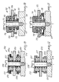
- figure 10 illustrates a different embodiment of the vibration damping device 102, which comprises a T-shaped rigid spacer 107 which is associated with the ski 101 by means of the screw 108 with the interposition of a possible washer 110.
- the rigid spacer 107 interacts with a bush 112 which has the shape of an inverted cup directed toward the ski 101; an opening 113 is defined on the bottom of said bush and is slightly larger in diameter than the opening of said rigid spacer 107.
- the internal diameter of the lateral wall of the bush 112 is instead larger than the outer diameter of the rigid spacer, so as to define a seat for a first resilient member which is constituted by a first spring 114 which is interposed between the bottom of the bush 112 which is adjacent to the head of the screw 108 and the ski 101.
- Said bush 112 has, at its open end which is adjacent to the ski 101, an annular raised portion 115 which defines a resting abutment for the rigid plate 103 which thus has an adapted hole 106.
- a second resilient member constituted by a second spring 117, can be interposed between the rigid plate 103 and the overlying head 116 of the rigid spacer 107.
- the first spring 114 forces the bottom of the bush 112 into contact with the head 116 of the rigid spacer 107, whereas the second spring 117 forces the rigid plate 103 at the annular raised portion 115 of said bush 112.
- the terminal end of the annular raised portion 115 is arranged at a preset distance from the facing surface of the ski 101.
- the distance between the end of the annular raised portion 115 and the surface of the ski 101 advantageously corresponds to the maximum extent of the vibration which can be damped by the first spring 114 so as to prevent said spring from packing during the damping of vibrations, thus yielding.
- the function of the first and second springs is naturally respectively that of damping the vibrations in the direction of the ski and in the direction of the head 116 of the rigid spacer 107.
- figure 11 illustrates a means suitable for limiting the axial stroke of the first spring 114, which is constituted by an internally threaded ring 118 which is associated with a complementary thread defined outside the annular raised portion 115.
- the skier can thus, by rotating the ring 118, preset the maximum extent of the oscillation of the first spring 114, this depending essentially on variables such as the weight of the skier, the type of snow, the rigidity of the ski and the skiing speed.
- FIGS 12 and 13 illustrate a third embodiment for a vibration damping device 202 which again comprises a rigid spacer 207 which is associated with the ski 201 by means of an adapted screw 208 which interacts with an adapted washer 210 which abuts on said rigid spacer.
- the device comprises a first spring 214 and a second spring 217 which are arranged coaxially with respect to the rigid spacer 207 and are respectively interposed between the lower surface of the rigid plate 203 and the facing upper surface of the ski 201 and between the upper surface of the rigid plate 203 and the facing lower surface of the washer 210.
- said washer has, at its perimetric edge, a tab 219 which protrudes toward the ski 201 and allows to contain an end of the second spring 217.
- said second tab 219 can be externally threaded in order to be able to associate therewith a complementarily threaded first ring 218a for adjusting the distance between the terminal end of said tab 219 and the underlying surface of the rigid plate 203.
- first spring 214 In order to obtain a similar adjustment for the first spring 214, it is possible to provide, coaxially to said first spring, a cylinder 220; the end of said cylinder which is adjacent to the rigid plate 203 is threaded externally so as to be able to interact with a complementarily threaded second ring 218b.
Landscapes
- Vibration Prevention Devices (AREA)
- Addition Polymer Or Copolymer, Post-Treatments, Or Chemical Modifications (AREA)
- Footwear And Its Accessory, Manufacturing Method And Apparatuses (AREA)
Applications Claiming Priority (2)
| Application Number | Priority Date | Filing Date | Title |
|---|---|---|---|
| IT08260790A IT1242750B (it) | 1990-07-30 | 1990-07-30 | Dispositivo per l'assorbimento delle vibrazioni, particolarmente per sci |
| IT8260790 | 1990-07-30 |
Publications (2)
| Publication Number | Publication Date |
|---|---|
| EP0469452A1 true EP0469452A1 (de) | 1992-02-05 |
| EP0469452B1 EP0469452B1 (de) | 1995-05-03 |
Family
ID=11319056
Family Applications (1)
| Application Number | Title | Priority Date | Filing Date |
|---|---|---|---|
| EP91112408A Expired - Lifetime EP0469452B1 (de) | 1990-07-30 | 1991-07-24 | Vibrationsdämpfungseinrichtung, insbesondere für Skis |
Country Status (6)
| Country | Link |
|---|---|
| US (1) | US5167424A (de) |
| EP (1) | EP0469452B1 (de) |
| JP (1) | JPH04250181A (de) |
| AT (1) | ATE121959T1 (de) |
| DE (1) | DE69109394T2 (de) |
| IT (1) | IT1242750B (de) |
Cited By (9)
| Publication number | Priority date | Publication date | Assignee | Title |
|---|---|---|---|---|
| EP0490824A1 (de) * | 1990-12-10 | 1992-06-17 | Skis Rossignol S.A. | Skibindung |
| US5431427A (en) * | 1992-07-15 | 1995-07-11 | Fischer Gesellschaft M.B.H. | Ski having a binding mounting plate fitted above the ski body, at least partly at a distance therefrom and in fixed relationship thereto |
| EP0791378A3 (de) * | 1996-02-24 | 1998-06-24 | Franz Völkl GmbH & Co. Ski und Tennis Sportartikelfabrik KG | Tragplatte |
| US5845923A (en) * | 1995-05-17 | 1998-12-08 | Skis Rossignol S.A. | Device for raising a ski binding and ski equipped with such a device |
| EP0854745A4 (de) * | 1995-10-02 | 1998-12-09 | Kaj Gyr | Snowboarbindungssystem |
| WO2000069980A3 (en) * | 1999-05-14 | 2002-10-24 | Milan Trnka | Connector plate for bindings |
| EP2036596A1 (de) * | 2007-09-14 | 2009-03-18 | Daniel Brillat | Dämpfungsvorrichtung für eine Schuhbindung auf einem Snowboard oder Rollerboard und Verfahren zur Umsetzung dieser Vorrichtung |
| WO2009033307A1 (fr) * | 2007-09-14 | 2009-03-19 | Daniel Brillat | Dispositif amortisseur pour une fixation de chaussure sur une planche de glisse ou de roulage et procede de mise en oeuvre de ce dispositif |
| WO2026117803A1 (en) | 2024-12-06 | 2026-06-11 | Segl Jakob Valentin | Suspension device |
Families Citing this family (10)
| Publication number | Priority date | Publication date | Assignee | Title |
|---|---|---|---|---|
| US5803478A (en) * | 1995-06-07 | 1998-09-08 | Gavalis; Richard Clifford | Ski |
| US5785342A (en) * | 1996-07-30 | 1998-07-28 | Bronson; Henry D. | Ski binding dampening assembly |
| US20040100069A1 (en) * | 2002-11-22 | 2004-05-27 | Cumby Brian Furneaux | Snowboard suspension device |
| US7159892B2 (en) * | 2002-12-19 | 2007-01-09 | K-2 Corporation | Snowboard binding with suspension heel loop |
| GB2474417A (en) * | 2009-07-03 | 2011-04-20 | Isis Innovation | A spring and a spring assembly |
| US9526971B1 (en) | 2015-09-18 | 2016-12-27 | Rossland Binding Company | Remote release ski binding |
| US11065529B2 (en) * | 2016-04-22 | 2021-07-20 | Jan Peter Ortwig | Method of and apparatus for changing a shape of a gliding surface of a gliding device |
| US10729968B2 (en) | 2018-05-25 | 2020-08-04 | Rossland Binding Company | Remote release snowboard binding |
| JP7029352B2 (ja) * | 2018-05-30 | 2022-03-03 | 株式会社カーメイト | スノーボード用バインディング |
| CH721263A2 (de) * | 2023-11-01 | 2025-05-15 | Duss Skifederung Ag | Schneegleiter-Bindungsbefestigung |
Citations (4)
| Publication number | Priority date | Publication date | Assignee | Title |
|---|---|---|---|---|
| US3797844A (en) * | 1970-09-28 | 1974-03-19 | Gertsch Ag | Ski binding |
| US4141570A (en) * | 1977-10-17 | 1979-02-27 | Sudmeier James L | Adjustable connection between ski and binding |
| US4565386A (en) * | 1984-02-01 | 1986-01-21 | Design Standards Corporation | Ski |
| FR2637192A1 (fr) * | 1988-09-30 | 1990-04-06 | Varpat Patentverwertung | Systeme d'assemblage, en particulier pour la fixation d'une chaussure de ski a la surface superieure d'un ski |
Family Cites Families (9)
| Publication number | Priority date | Publication date | Assignee | Title |
|---|---|---|---|---|
| US3260532A (en) * | 1965-04-02 | 1966-07-12 | Johan G F Heuvel | Ski binding mounting and runner construction |
| DE2122358A1 (de) * | 1971-05-06 | 1972-11-16 | Klöckner-Humboldt-Deutz AG, 5000 Köln | Elastische Lagerung für Maschinen |
| US3809427A (en) * | 1972-10-03 | 1974-05-07 | Bennett Equipment Corp | Vehicle body mount |
| DE2255406A1 (de) * | 1972-11-11 | 1974-05-16 | Wolf Dieter Hellmann | Vorrichtung zur zuordnung der fussaufstellflaeche zu skiern |
| DE2601951C2 (de) * | 1976-01-20 | 1982-04-22 | Hans 8000 München Meyer | Ski |
| GB1555429A (en) * | 1976-11-15 | 1979-11-07 | Caterpillar Tractor Co | Mouting grommet |
| DE2752206C3 (de) * | 1977-11-23 | 1986-03-27 | Bernhard 5500 Trier Kirsch | Sohlenplatte für Skibindungen |
| CH671887A5 (de) * | 1982-03-25 | 1989-10-13 | Brosi Bettosini | |
| FR2638650A1 (fr) * | 1988-11-04 | 1990-05-11 | Salomon Sa | Dispositif amortisseur de chocs et vibrations entre un ski et la fixation de la chaussure |
-
1990
- 1990-07-30 IT IT08260790A patent/IT1242750B/it active IP Right Grant
-
1991
- 1991-07-24 DE DE69109394T patent/DE69109394T2/de not_active Expired - Fee Related
- 1991-07-24 EP EP91112408A patent/EP0469452B1/de not_active Expired - Lifetime
- 1991-07-24 AT AT91112408T patent/ATE121959T1/de not_active IP Right Cessation
- 1991-07-26 US US07/736,534 patent/US5167424A/en not_active Expired - Fee Related
- 1991-07-30 JP JP91212891A patent/JPH04250181A/ja not_active Withdrawn
Patent Citations (4)
| Publication number | Priority date | Publication date | Assignee | Title |
|---|---|---|---|---|
| US3797844A (en) * | 1970-09-28 | 1974-03-19 | Gertsch Ag | Ski binding |
| US4141570A (en) * | 1977-10-17 | 1979-02-27 | Sudmeier James L | Adjustable connection between ski and binding |
| US4565386A (en) * | 1984-02-01 | 1986-01-21 | Design Standards Corporation | Ski |
| FR2637192A1 (fr) * | 1988-09-30 | 1990-04-06 | Varpat Patentverwertung | Systeme d'assemblage, en particulier pour la fixation d'une chaussure de ski a la surface superieure d'un ski |
Cited By (11)
| Publication number | Priority date | Publication date | Assignee | Title |
|---|---|---|---|---|
| EP0490824A1 (de) * | 1990-12-10 | 1992-06-17 | Skis Rossignol S.A. | Skibindung |
| US5431427A (en) * | 1992-07-15 | 1995-07-11 | Fischer Gesellschaft M.B.H. | Ski having a binding mounting plate fitted above the ski body, at least partly at a distance therefrom and in fixed relationship thereto |
| AT401009B (de) * | 1992-07-15 | 1996-05-28 | Fischer Gmbh | Ski |
| US5845923A (en) * | 1995-05-17 | 1998-12-08 | Skis Rossignol S.A. | Device for raising a ski binding and ski equipped with such a device |
| EP0854745A4 (de) * | 1995-10-02 | 1998-12-09 | Kaj Gyr | Snowboarbindungssystem |
| EP0791378A3 (de) * | 1996-02-24 | 1998-06-24 | Franz Völkl GmbH & Co. Ski und Tennis Sportartikelfabrik KG | Tragplatte |
| WO2000069980A3 (en) * | 1999-05-14 | 2002-10-24 | Milan Trnka | Connector plate for bindings |
| US6659493B1 (en) | 1999-05-14 | 2003-12-09 | Milan Trnka | Connector plate for bindings |
| EP2036596A1 (de) * | 2007-09-14 | 2009-03-18 | Daniel Brillat | Dämpfungsvorrichtung für eine Schuhbindung auf einem Snowboard oder Rollerboard und Verfahren zur Umsetzung dieser Vorrichtung |
| WO2009033307A1 (fr) * | 2007-09-14 | 2009-03-19 | Daniel Brillat | Dispositif amortisseur pour une fixation de chaussure sur une planche de glisse ou de roulage et procede de mise en oeuvre de ce dispositif |
| WO2026117803A1 (en) | 2024-12-06 | 2026-06-11 | Segl Jakob Valentin | Suspension device |
Also Published As
| Publication number | Publication date |
|---|---|
| DE69109394D1 (de) | 1995-06-08 |
| IT9082607A0 (it) | 1990-07-30 |
| EP0469452B1 (de) | 1995-05-03 |
| DE69109394T2 (de) | 1995-09-07 |
| IT9082607A1 (it) | 1992-01-30 |
| IT1242750B (it) | 1994-05-17 |
| JPH04250181A (ja) | 1992-09-07 |
| ATE121959T1 (de) | 1995-05-15 |
| US5167424A (en) | 1992-12-01 |
Similar Documents
| Publication | Publication Date | Title |
|---|---|---|
| US5167424A (en) | Vibration damping device particularly for skis | |
| EP0559179A1 (de) | Einspurrollschuhe | |
| JP2635501B2 (ja) | スキー | |
| US5332253A (en) | Device for the modifying the pressure distribution of a ski along its sliding surface | |
| WO1993012847A1 (en) | Skate with aligned wheels | |
| WO1993008883A1 (en) | Apparatus and method for damping deflections and vibrations in skis | |
| EP0585764B1 (de) | Bremsvorrichtung besonders für Rollschuhe | |
| US4147378A (en) | Device for use with a ski binding | |
| US4979761A (en) | Ski suspension | |
| US20080209768A1 (en) | Sports shoe, in particular an alpine ski shoe | |
| EP0686413B1 (de) | Rollschuhe mit verbessertem Komfort | |
| US20010052687A1 (en) | Alpine ski | |
| US5746439A (en) | Spacer-plate arrangement for ski bindings | |
| US6616171B2 (en) | Device for raising at least one binding element used on a board for gliding | |
| EP0467142B1 (de) | Hintere einstellbare Stützvorrichtung, insbesondere für Skischuhe | |
| US5344180A (en) | Safety ski binding | |
| EP0468170B1 (de) | Flexible Einstellvorrichtung, insbesondere für Skischuhe | |
| US5683095A (en) | Interface between front and rear ski bindings | |
| US6102425A (en) | Device for purposely influencing the longitudinal curvature of a ski | |
| EP0848971A1 (de) | Einspurrollschuhe | |
| US4696117A (en) | Spring structure for ski boot | |
| EP0993326B1 (de) | Ergonomischer rollschuh mit stossdämpfer | |
| US5566968A (en) | Alpine ski binding element equipped with a compensation device | |
| US20020030349A1 (en) | Snowboarding boot | |
| EP0240981A2 (de) | Skistiefel |
Legal Events
| Date | Code | Title | Description |
|---|---|---|---|
| PUAI | Public reference made under article 153(3) epc to a published international application that has entered the european phase |
Free format text: ORIGINAL CODE: 0009012 |
|
| AK | Designated contracting states |
Kind code of ref document: A1 Designated state(s): AT CH DE FR IT LI |
|
| 17P | Request for examination filed |
Effective date: 19920701 |
|
| 17Q | First examination report despatched |
Effective date: 19930901 |
|
| RAP3 | Party data changed (applicant data changed or rights of an application transferred) |
Owner name: NORDICA S.P.A |
|
| GRAA | (expected) grant |
Free format text: ORIGINAL CODE: 0009210 |
|
| AK | Designated contracting states |
Kind code of ref document: B1 Designated state(s): AT CH DE FR IT LI |
|
| REF | Corresponds to: |
Ref document number: 121959 Country of ref document: AT Date of ref document: 19950515 Kind code of ref document: T |
|
| REF | Corresponds to: |
Ref document number: 69109394 Country of ref document: DE Date of ref document: 19950608 |
|
| ITF | It: translation for a ep patent filed | ||
| ET | Fr: translation filed | ||
| PLBE | No opposition filed within time limit |
Free format text: ORIGINAL CODE: 0009261 |
|
| STAA | Information on the status of an ep patent application or granted ep patent |
Free format text: STATUS: NO OPPOSITION FILED WITHIN TIME LIMIT |
|
| 26N | No opposition filed | ||
| PGFP | Annual fee paid to national office [announced via postgrant information from national office to epo] |
Ref country code: CH Payment date: 19960802 Year of fee payment: 6 |
|
| PGFP | Annual fee paid to national office [announced via postgrant information from national office to epo] |
Ref country code: FR Payment date: 19970627 Year of fee payment: 7 |
|
| PGFP | Annual fee paid to national office [announced via postgrant information from national office to epo] |
Ref country code: AT Payment date: 19970724 Year of fee payment: 7 |
|
| PG25 | Lapsed in a contracting state [announced via postgrant information from national office to epo] |
Ref country code: LI Free format text: LAPSE BECAUSE OF NON-PAYMENT OF DUE FEES Effective date: 19970731 Ref country code: CH Free format text: LAPSE BECAUSE OF NON-PAYMENT OF DUE FEES Effective date: 19970731 |
|
| PGFP | Annual fee paid to national office [announced via postgrant information from national office to epo] |
Ref country code: DE Payment date: 19970924 Year of fee payment: 7 |
|
| REG | Reference to a national code |
Ref country code: CH Ref legal event code: PL |
|
| PG25 | Lapsed in a contracting state [announced via postgrant information from national office to epo] |
Ref country code: AT Free format text: LAPSE BECAUSE OF NON-PAYMENT OF DUE FEES Effective date: 19980724 |
|
| PG25 | Lapsed in a contracting state [announced via postgrant information from national office to epo] |
Ref country code: FR Free format text: LAPSE BECAUSE OF NON-PAYMENT OF DUE FEES Effective date: 19990331 |
|
| PG25 | Lapsed in a contracting state [announced via postgrant information from national office to epo] |
Ref country code: DE Free format text: LAPSE BECAUSE OF NON-PAYMENT OF DUE FEES Effective date: 19990501 |
|
| REG | Reference to a national code |
Ref country code: FR Ref legal event code: ST |
|
| PG25 | Lapsed in a contracting state [announced via postgrant information from national office to epo] |
Ref country code: IT Free format text: LAPSE BECAUSE OF NON-PAYMENT OF DUE FEES;WARNING: LAPSES OF ITALIAN PATENTS WITH EFFECTIVE DATE BEFORE 2007 MAY HAVE OCCURRED AT ANY TIME BEFORE 2007. THE CORRECT EFFECTIVE DATE MAY BE DIFFERENT FROM THE ONE RECORDED. Effective date: 20050724 |