EP0469508A1 - Verfahren und Vorrichtung zur Schätzung des magnetischen Induktionsflusses eines Asynchronmotors, insbesondere im Hinblick auf die Steuerung des Motors durch Flussregelung - Google Patents
Verfahren und Vorrichtung zur Schätzung des magnetischen Induktionsflusses eines Asynchronmotors, insbesondere im Hinblick auf die Steuerung des Motors durch Flussregelung Download PDFInfo
- Publication number
- EP0469508A1 EP0469508A1 EP91112698A EP91112698A EP0469508A1 EP 0469508 A1 EP0469508 A1 EP 0469508A1 EP 91112698 A EP91112698 A EP 91112698A EP 91112698 A EP91112698 A EP 91112698A EP 0469508 A1 EP0469508 A1 EP 0469508A1
- Authority
- EP
- European Patent Office
- Prior art keywords
- flux
- motor
- measured
- expression
- flow
- Prior art date
- Legal status (The legal status is an assumption and is not a legal conclusion. Google has not performed a legal analysis and makes no representation as to the accuracy of the status listed.)
- Granted
Links
Images
Classifications
-
- H—ELECTRICITY
- H02—GENERATION; CONVERSION OR DISTRIBUTION OF ELECTRIC POWER
- H02P—CONTROL OR REGULATION OF ELECTRIC MOTORS, ELECTRIC GENERATORS OR DYNAMO-ELECTRIC CONVERTERS; CONTROLLING TRANSFORMERS, REACTORS OR CHOKE COILS
- H02P21/00—Arrangements or methods for the control of electric machines by vector control, e.g. by control of field orientation
- H02P21/14—Estimation or adaptation of machine parameters, e.g. flux, current or voltage
- H02P21/141—Flux estimation
Definitions
- the present invention relates to a method and a device for estimating the magnetic, stator, gap, or rotor induction flow of an asynchronous motor, with a view in particular to controlling this motor by flow regulation.
- Such a control requires a flux measurement, for example of the rotor flux, which has hitherto been carried out either by providing additional turns to the rotor and by deducing this flux from the voltage observed at the terminals of these turns, or by carrying out measurements. of stator voltage and current and by deducting this flow from these measurements and from characteristic parameters of the motor, from the equations defining the operation of the motor.
- the first method has the disadvantage, in addition to posing practical implementation problems, of being unreliable, because the flow sensor, installed directly in the engine, is subjected to a relatively aggressive environment in temperature, humidity, pollution, vibrations, shocks ... etc.
- the second method has the disadvantage of having its reliability affected by variations, as a function of the thermal state of the engine, of at least one of said characteristic parameters of the engine, in particular its stator resistance.
- the present invention relates to a method and a device for estimating the magnetic induction flux of an asynchronous motor making it possible to avoid these drawbacks.
- the flux estimation consists of an rotor flux estimation, the voltages and currents measured then being the voltage and the stator current and said parameter having a predetermined value which can differ notably from its real value being the stator resistance, these two examples differing from each other by the method of calculating the so-called estimated flux.
- V s and I s denote the stator voltage and the stator current measured respectively. These quantities are measured by conventional means which will therefore not be described again here.
- the so-called measured rotor flux ⁇ rmes is defined by: where the symbol * means that the values of the corresponding parameters are predetermined values, which may differ from the actual values depending on the operating point of the engine but which remain very close to these real values in the case of the parameters L, * , L m * , a * and L s * and which can on the other hand differ significantly in the case of the parameter R s , for example in a ratio 2 for a given temperature range of engine operation.
- This measured rotor flux is calculated by conventional calculation means which will therefore not be described again here.
- a so-called estimated flux according to an expression deduced from the engine operating equations and as a function of the measured flux, of characteristic parameters of the motor other than the stator resistance and possibly of the voltage measurements. or motor current.
- I d and I m be the projections of I S according to the vectors ⁇ rmes and ⁇ r , that is to say the components of I s along the direct axis of landmarks linked respectively to the measured rotor flux ⁇ rmes and to the real rotor flux ⁇ r.
- Equation (5) is then written: From where :
- the estimated flow ⁇ r is then defined as representing an approximate value of the real flow ⁇ r , by the relation:
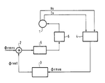
- FIG. 1 a block diagram of a device for controlling an asynchronous motor 1 by slaving of its rotor flux to a set value ⁇ rcons.
- a difference detector 2 detects a possible difference between this set value and the value of the estimated rotor flux flux rest from a calculation means 3 which operates according to one or the other of the methods described above, with starting from a value of measured flux ⁇ rmes itself resulting from a calculation means 4 operating, in a conventional manner, from measured values of the stator voltage V s and of the stator current I s .
- Either one (9) or (16) of the expressions giving the estimated flux ⁇ rest can be calculated by conventional calculation means which therefore do not require any particular description.
- the difference detected by the deviation detector 2 is applied to a regulation means 5, before application to a member 6 for controlling the motor, which is also conventional.
Landscapes
- Engineering & Computer Science (AREA)
- Power Engineering (AREA)
- Control Of Ac Motors In General (AREA)
- Motor And Converter Starters (AREA)
Applications Claiming Priority (2)
| Application Number | Priority Date | Filing Date | Title |
|---|---|---|---|
| FR9009848A FR2665589B1 (fr) | 1990-08-01 | 1990-08-01 | Procede et dispositif d'estimation de flux d'induction magnetique d'un moteur asynchrone, en vue notamment de la commande de ce moteur par regulation de flux. |
| FR9009848 | 1990-08-01 |
Publications (2)
| Publication Number | Publication Date |
|---|---|
| EP0469508A1 true EP0469508A1 (de) | 1992-02-05 |
| EP0469508B1 EP0469508B1 (de) | 1995-01-18 |
Family
ID=9399326
Family Applications (1)
| Application Number | Title | Priority Date | Filing Date |
|---|---|---|---|
| EP91112698A Expired - Lifetime EP0469508B1 (de) | 1990-08-01 | 1991-07-29 | Verfahren und Vorrichtung zur Schätzung des magnetischen Induktionsflusses eines Asynchronmotors, insbesondere im Hinblick auf die Steuerung des Motors durch Flussregelung |
Country Status (6)
| Country | Link |
|---|---|
| US (1) | US5170116A (de) |
| EP (1) | EP0469508B1 (de) |
| AT (1) | ATE117475T1 (de) |
| DE (1) | DE69106808T2 (de) |
| ES (1) | ES2068440T3 (de) |
| FR (1) | FR2665589B1 (de) |
Cited By (1)
| Publication number | Priority date | Publication date | Assignee | Title |
|---|---|---|---|---|
| CN110855205A (zh) * | 2018-07-26 | 2020-02-28 | 西门子歌美飒可再生能源公司 | 评估风力涡轮发电机转子温度 |
Families Citing this family (9)
| Publication number | Priority date | Publication date | Assignee | Title |
|---|---|---|---|---|
| US6870348B2 (en) * | 2003-08-06 | 2005-03-22 | General Motors Corporation | Rotor resistance adaptation for indirect field oriented control of induction machine |
| RU2319160C2 (ru) * | 2005-09-27 | 2008-03-10 | Академический институт прикладной энергетики | Способ контроля магнитного состояния статора погружного асинхронного электродвигателя (пэд) |
| JP4961292B2 (ja) * | 2007-07-27 | 2012-06-27 | 三洋電機株式会社 | モータ制御装置 |
| EP2432114B1 (de) * | 2010-09-16 | 2013-11-20 | ABB Technology AG | Kompensation des Fluss-Offsets für eine elektrische Rotationsmaschine |
| FR2985113B1 (fr) * | 2011-12-21 | 2014-01-24 | Michelin Soc Tech | Onduleur de pilotage avec detecteur d'ondulation anormale de couple |
| DE102016123261A1 (de) * | 2016-12-01 | 2018-06-07 | Beckhoff Automation Gmbh | Verfahren und Vorrichtung zum Betreiben einer elektrischen Maschine, elektrische Maschine und Computerprogramm |
| FR3066276B1 (fr) * | 2017-05-10 | 2019-04-26 | Schneider Toshiba Inverter Europe Sas | Procede d'identification de la resistance electrique du rotor d'un moteur electrique |
| FR3070805B1 (fr) * | 2017-09-01 | 2019-08-23 | Schneider Toshiba Inverter Europe Sas | Procede d'identification des parametres de saturation magnetique d'un moteur electrique asynchrone |
| CN114123898B (zh) * | 2021-12-02 | 2023-08-11 | 郑州轻工业大学 | 车用感应电机驱动力矩高性能分时控制系统及控制方法 |
Citations (3)
| Publication number | Priority date | Publication date | Assignee | Title |
|---|---|---|---|---|
| US4431957A (en) * | 1981-12-29 | 1984-02-14 | General Electric Company | Method and apparatus for generating signals representing motor flux in an AC motor |
| US4470000A (en) * | 1981-09-28 | 1984-09-04 | Siemens Aktiengesellschaft | Apparatus and method for simulating the machine flux of a rotating field machine |
| EP0335180A1 (de) * | 1988-03-28 | 1989-10-04 | Siemens Aktiengesellschaft | Vorrichtung zur Lastwinkelregelung eines Stromrichters |
Family Cites Families (4)
| Publication number | Priority date | Publication date | Assignee | Title |
|---|---|---|---|---|
| US4245181A (en) * | 1979-02-26 | 1981-01-13 | General Electric Company | Method and apparatus for generating an air gap flux signal for an AC machine from AC line voltage and current values |
| NO851324L (no) * | 1984-05-18 | 1985-11-19 | Siemens Ag | Fremgangsmaate og anordning til aa bestemme en dreiefelt-maskins fluksvektor. |
| US4724373A (en) * | 1986-02-20 | 1988-02-09 | Wisconsin Alumni Research Foundation | Method and apparatus for flux and torque sensing in electrical machines |
| JP2780263B2 (ja) * | 1988-02-23 | 1998-07-30 | 株式会社明電舎 | 誘導電動機のベクトル制御方法と装置 |
-
1990
- 1990-08-01 FR FR9009848A patent/FR2665589B1/fr not_active Expired - Lifetime
-
1991
- 1991-07-29 EP EP91112698A patent/EP0469508B1/de not_active Expired - Lifetime
- 1991-07-29 ES ES91112698T patent/ES2068440T3/es not_active Expired - Lifetime
- 1991-07-29 AT AT91112698T patent/ATE117475T1/de active
- 1991-07-29 DE DE69106808T patent/DE69106808T2/de not_active Expired - Fee Related
- 1991-08-01 US US07/739,031 patent/US5170116A/en not_active Expired - Fee Related
Patent Citations (3)
| Publication number | Priority date | Publication date | Assignee | Title |
|---|---|---|---|---|
| US4470000A (en) * | 1981-09-28 | 1984-09-04 | Siemens Aktiengesellschaft | Apparatus and method for simulating the machine flux of a rotating field machine |
| US4431957A (en) * | 1981-12-29 | 1984-02-14 | General Electric Company | Method and apparatus for generating signals representing motor flux in an AC motor |
| EP0335180A1 (de) * | 1988-03-28 | 1989-10-04 | Siemens Aktiengesellschaft | Vorrichtung zur Lastwinkelregelung eines Stromrichters |
Cited By (2)
| Publication number | Priority date | Publication date | Assignee | Title |
|---|---|---|---|---|
| CN110855205A (zh) * | 2018-07-26 | 2020-02-28 | 西门子歌美飒可再生能源公司 | 评估风力涡轮发电机转子温度 |
| CN110855205B (zh) * | 2018-07-26 | 2023-06-02 | 西门子歌美飒可再生能源公司 | 评估风力涡轮发电机转子温度 |
Also Published As
| Publication number | Publication date |
|---|---|
| DE69106808T2 (de) | 1995-05-18 |
| EP0469508B1 (de) | 1995-01-18 |
| FR2665589B1 (fr) | 1992-10-09 |
| ES2068440T3 (es) | 1995-04-16 |
| DE69106808D1 (de) | 1995-03-02 |
| US5170116A (en) | 1992-12-08 |
| FR2665589A1 (fr) | 1992-02-07 |
| ATE117475T1 (de) | 1995-02-15 |
Similar Documents
| Publication | Publication Date | Title |
|---|---|---|
| EP0469508B1 (de) | Verfahren und Vorrichtung zur Schätzung des magnetischen Induktionsflusses eines Asynchronmotors, insbesondere im Hinblick auf die Steuerung des Motors durch Flussregelung | |
| EP1713173B1 (de) | Verfahren zur Justierung der Parameter eines Elektromotors und Verwendung eines solchen Verfahrens in einer Drehzahlregelung | |
| KR102281866B1 (ko) | 영구자석 동기전동기의 부하토크 추정 시스템 및 이를 이용한 영구자석 동기전동기의 속도 제어 시스템 | |
| WO1996020528A1 (fr) | Appareil et methode pour demarrer une machine synchrone | |
| EP0128865A1 (de) | Verfahren zur Verbesserung der Dämpfung bei der Stillegung eines Polyphasenmotors, insbesondere eines Schrittmotors, und Anordnung für die Durchführung des Verfahrens | |
| EP0660502B1 (de) | Wirbelstronbremse mit Drehmomentschätzung | |
| EP0469509B1 (de) | Verfahren und Vorrichtung zur Steuerung eines Asynchronmotors durch Regelung des magnetischen Induktionsflusses | |
| WO2020020924A1 (fr) | Procede de verification du calage d'un capteur de position angulaire d'un rotor pour vehicule | |
| EP3221958A1 (de) | Verfahren zur steuerung einer elektrischen synchronmaschine mit einem gewickelten rotor | |
| EP2870018A2 (de) | Verfahren zur steuerung eines antriebsstranges und entsprechendes system | |
| EP2810367A1 (de) | Steuerung einer elektrischen permanentmagnetmaschine | |
| EP0407253B1 (de) | Dynamische Messvorrichtung für das Drehmoment eines Asynchronmotors und angehörige Asynchronmotorregelvorrichtung | |
| EP3476037A1 (de) | Verfahren zum schätzen der position und geschwindigkeit des rotors einer wechselstrommaschine für ein kraftfahrzeug und entsprechendes system | |
| EP4587805A1 (de) | Verfahren zur kalibrierung eines modells zur schätzung eines von einer elektrischen maschine gelieferten drehmoments | |
| FR2713284A1 (fr) | Circuit pour préparer le signal fourni par un capteur appliqué à une sonde de gaz exposée aux gaz d'échappement d'un moteur à combustion interne. | |
| EP4416835A1 (de) | Verfahren zur schätzung der position und geschwindigkeit des rotors eines permanentmagnet-synchronmotors | |
| EP3853994B1 (de) | Verfahren zur bestimmung des magnetischen durchflusses einer elektromaschine | |
| FR3028362A1 (fr) | Procede et systeme de commande d'une machine electrique synchrone a aimants permanents. | |
| EP3012962A1 (de) | Steuerungsverfahren einer synchronlaufenden drehstrom-elektromaschine mit schleifringläufer | |
| FR2729752A1 (fr) | Procede et dispositif de compensation thermique d'un gyrometre | |
| EP3824540B1 (de) | Positions und geschwindigkeitsbestimmung eines wickelrotor einer elektrischen synchronmaschine verfahren | |
| FR3160463A1 (fr) | Méthode de détermination de la position angulaire d’un rotor de machine électrique | |
| EP3602773B1 (de) | Verfahren zur bestimmung der intensität und des elektromagnetischen drehmoments einer asynchronen elektrischen maschine während des betriebs | |
| WO2023118680A1 (fr) | Système et procédé de commande d'un moteur électrique triphasé | |
| EP0532395B1 (de) | Verfahren und Vorrichtung zur Steuerung von Asynchronmotoren in Parallele |
Legal Events
| Date | Code | Title | Description |
|---|---|---|---|
| PUAI | Public reference made under article 153(3) epc to a published international application that has entered the european phase |
Free format text: ORIGINAL CODE: 0009012 |
|
| AK | Designated contracting states |
Kind code of ref document: A1 Designated state(s): AT BE CH DE ES FR GB IT LI NL SE |
|
| 17P | Request for examination filed |
Effective date: 19920803 |
|
| 17Q | First examination report despatched |
Effective date: 19940413 |
|
| GRAA | (expected) grant |
Free format text: ORIGINAL CODE: 0009210 |
|
| AK | Designated contracting states |
Kind code of ref document: B1 Designated state(s): AT BE CH DE ES FR GB IT LI NL SE |
|
| REF | Corresponds to: |
Ref document number: 117475 Country of ref document: AT Date of ref document: 19950215 Kind code of ref document: T |
|
| REF | Corresponds to: |
Ref document number: 69106808 Country of ref document: DE Date of ref document: 19950302 |
|
| ITF | It: translation for a ep patent filed | ||
| GBT | Gb: translation of ep patent filed (gb section 77(6)(a)/1977) |
Effective date: 19950307 |
|
| REG | Reference to a national code |
Ref country code: ES Ref legal event code: FG2A Ref document number: 2068440 Country of ref document: ES Kind code of ref document: T3 |
|
| PLBE | No opposition filed within time limit |
Free format text: ORIGINAL CODE: 0009261 |
|
| STAA | Information on the status of an ep patent application or granted ep patent |
Free format text: STATUS: NO OPPOSITION FILED WITHIN TIME LIMIT |
|
| 26N | No opposition filed | ||
| PGFP | Annual fee paid to national office [announced via postgrant information from national office to epo] |
Ref country code: GB Payment date: 20000614 Year of fee payment: 10 |
|
| PGFP | Annual fee paid to national office [announced via postgrant information from national office to epo] |
Ref country code: CH Payment date: 20000616 Year of fee payment: 10 |
|
| PGFP | Annual fee paid to national office [announced via postgrant information from national office to epo] |
Ref country code: NL Payment date: 20000620 Year of fee payment: 10 |
|
| PGFP | Annual fee paid to national office [announced via postgrant information from national office to epo] |
Ref country code: AT Payment date: 20000622 Year of fee payment: 10 |
|
| PGFP | Annual fee paid to national office [announced via postgrant information from national office to epo] |
Ref country code: SE Payment date: 20000626 Year of fee payment: 10 |
|
| PGFP | Annual fee paid to national office [announced via postgrant information from national office to epo] |
Ref country code: FR Payment date: 20000629 Year of fee payment: 10 Ref country code: DE Payment date: 20000629 Year of fee payment: 10 |
|
| PGFP | Annual fee paid to national office [announced via postgrant information from national office to epo] |
Ref country code: BE Payment date: 20000704 Year of fee payment: 10 |
|
| PGFP | Annual fee paid to national office [announced via postgrant information from national office to epo] |
Ref country code: ES Payment date: 20000720 Year of fee payment: 10 |
|
| PG25 | Lapsed in a contracting state [announced via postgrant information from national office to epo] |
Ref country code: GB Free format text: LAPSE BECAUSE OF NON-PAYMENT OF DUE FEES Effective date: 20010729 Ref country code: AT Free format text: LAPSE BECAUSE OF NON-PAYMENT OF DUE FEES Effective date: 20010729 |
|
| PG25 | Lapsed in a contracting state [announced via postgrant information from national office to epo] |
Ref country code: SE Free format text: LAPSE BECAUSE OF NON-PAYMENT OF DUE FEES Effective date: 20010730 Ref country code: ES Free format text: LAPSE BECAUSE OF NON-PAYMENT OF DUE FEES Effective date: 20010730 |
|
| PG25 | Lapsed in a contracting state [announced via postgrant information from national office to epo] |
Ref country code: LI Free format text: LAPSE BECAUSE OF NON-PAYMENT OF DUE FEES Effective date: 20010731 Ref country code: CH Free format text: LAPSE BECAUSE OF NON-PAYMENT OF DUE FEES Effective date: 20010731 Ref country code: BE Free format text: LAPSE BECAUSE OF NON-PAYMENT OF DUE FEES Effective date: 20010731 |
|
| BERE | Be: lapsed |
Owner name: S.A. GEC ALSTHOM Effective date: 20010731 |
|
| PG25 | Lapsed in a contracting state [announced via postgrant information from national office to epo] |
Ref country code: NL Free format text: LAPSE BECAUSE OF NON-PAYMENT OF DUE FEES Effective date: 20020201 |
|
| EUG | Se: european patent has lapsed |
Ref document number: 91112698.5 |
|
| REG | Reference to a national code |
Ref country code: CH Ref legal event code: PL |
|
| GBPC | Gb: european patent ceased through non-payment of renewal fee |
Effective date: 20010729 |
|
| PG25 | Lapsed in a contracting state [announced via postgrant information from national office to epo] |
Ref country code: FR Free format text: LAPSE BECAUSE OF NON-PAYMENT OF DUE FEES Effective date: 20020329 |
|
| NLV4 | Nl: lapsed or anulled due to non-payment of the annual fee |
Effective date: 20020201 |
|
| PG25 | Lapsed in a contracting state [announced via postgrant information from national office to epo] |
Ref country code: DE Free format text: LAPSE BECAUSE OF NON-PAYMENT OF DUE FEES Effective date: 20020501 |
|
| REG | Reference to a national code |
Ref country code: FR Ref legal event code: ST |
|
| REG | Reference to a national code |
Ref country code: ES Ref legal event code: FD2A Effective date: 20020810 |
|
| PG25 | Lapsed in a contracting state [announced via postgrant information from national office to epo] |
Ref country code: IT Free format text: LAPSE BECAUSE OF NON-PAYMENT OF DUE FEES;WARNING: LAPSES OF ITALIAN PATENTS WITH EFFECTIVE DATE BEFORE 2007 MAY HAVE OCCURRED AT ANY TIME BEFORE 2007. THE CORRECT EFFECTIVE DATE MAY BE DIFFERENT FROM THE ONE RECORDED. Effective date: 20050729 |