EP0469617B1 - System bestehend aus einem geschlossenen Regelkreis mit einem adaptiven Filter - Google Patents
System bestehend aus einem geschlossenen Regelkreis mit einem adaptiven Filter Download PDFInfo
- Publication number
- EP0469617B1 EP0469617B1 EP91112973A EP91112973A EP0469617B1 EP 0469617 B1 EP0469617 B1 EP 0469617B1 EP 91112973 A EP91112973 A EP 91112973A EP 91112973 A EP91112973 A EP 91112973A EP 0469617 B1 EP0469617 B1 EP 0469617B1
- Authority
- EP
- European Patent Office
- Prior art keywords
- filter
- motor
- motor speed
- signal
- reference signal
- Prior art date
- Legal status (The legal status is an assumption and is not a legal conclusion. Google has not performed a legal analysis and makes no representation as to the accuracy of the status listed.)
- Expired - Lifetime
Links
Images





Classifications
-
- H—ELECTRICITY
- H02—GENERATION; CONVERSION OR DISTRIBUTION OF ELECTRIC POWER
- H02P—CONTROL OR REGULATION OF ELECTRIC MOTORS, ELECTRIC GENERATORS OR DYNAMO-ELECTRIC CONVERTERS; CONTROLLING TRANSFORMERS, REACTORS OR CHOKE COILS
- H02P5/00—Arrangements specially adapted for regulating or controlling the speed or torque of two or more electric motors
-
- G—PHYSICS
- G05—CONTROLLING; REGULATING
- G05B—CONTROL OR REGULATING SYSTEMS IN GENERAL; FUNCTIONAL ELEMENTS OF SUCH SYSTEMS; MONITORING OR TESTING ARRANGEMENTS FOR SUCH SYSTEMS OR ELEMENTS
- G05B19/00—Program-control systems
- G05B19/02—Program-control systems electric
- G05B19/18—Numerical control [NC], i.e. automatically operating machines, in particular machine tools, e.g. in a manufacturing environment, so as to execute positioning, movement or co-ordinated operations by means of program data in numerical form
- G05B19/19—Numerical control [NC], i.e. automatically operating machines, in particular machine tools, e.g. in a manufacturing environment, so as to execute positioning, movement or co-ordinated operations by means of program data in numerical form characterised by positioning or contouring control systems, e.g. to control position from one programmed point to another or to control movement along a programmed continuous path
-
- H—ELECTRICITY
- H02—GENERATION; CONVERSION OR DISTRIBUTION OF ELECTRIC POWER
- H02P—CONTROL OR REGULATION OF ELECTRIC MOTORS, ELECTRIC GENERATORS OR DYNAMO-ELECTRIC CONVERTERS; CONTROLLING TRANSFORMERS, REACTORS OR CHOKE COILS
- H02P23/00—Arrangements or methods for the control of AC motors characterised by a control method other than vector control
- H02P23/16—Controlling the angular speed of one shaft
-
- G—PHYSICS
- G05—CONTROLLING; REGULATING
- G05B—CONTROL OR REGULATING SYSTEMS IN GENERAL; FUNCTIONAL ELEMENTS OF SUCH SYSTEMS; MONITORING OR TESTING ARRANGEMENTS FOR SUCH SYSTEMS OR ELEMENTS
- G05B2219/00—Program-control systems
- G05B2219/30—Nc systems
- G05B2219/41—Servomotor, servo controller till figures
- G05B2219/41166—Adaptive filter frequency as function of oscillation, rigidity, inertia load
-
- G—PHYSICS
- G05—CONTROLLING; REGULATING
- G05B—CONTROL OR REGULATING SYSTEMS IN GENERAL; FUNCTIONAL ELEMENTS OF SUCH SYSTEMS; MONITORING OR TESTING ARRANGEMENTS FOR SUCH SYSTEMS OR ELEMENTS
- G05B2219/00—Program-control systems
- G05B2219/30—Nc systems
- G05B2219/41—Servomotor, servo controller till figures
- G05B2219/41232—Notch filter
-
- G—PHYSICS
- G05—CONTROLLING; REGULATING
- G05B—CONTROL OR REGULATING SYSTEMS IN GENERAL; FUNCTIONAL ELEMENTS OF SUCH SYSTEMS; MONITORING OR TESTING ARRANGEMENTS FOR SUCH SYSTEMS OR ELEMENTS
- G05B2219/00—Program-control systems
- G05B2219/30—Nc systems
- G05B2219/41—Servomotor, servo controller till figures
- G05B2219/41344—Piezo, electrostrictive linear drive
-
- Y—GENERAL TAGGING OF NEW TECHNOLOGICAL DEVELOPMENTS; GENERAL TAGGING OF CROSS-SECTIONAL TECHNOLOGIES SPANNING OVER SEVERAL SECTIONS OF THE IPC; TECHNICAL SUBJECTS COVERED BY FORMER USPC CROSS-REFERENCE ART COLLECTIONS [XRACs] AND DIGESTS
- Y10—TECHNICAL SUBJECTS COVERED BY FORMER USPC
- Y10S—TECHNICAL SUBJECTS COVERED BY FORMER USPC CROSS-REFERENCE ART COLLECTIONS [XRACs] AND DIGESTS
- Y10S388/00—Electricity: motor control systems
- Y10S388/907—Specific control circuit element or device
- Y10S388/91—Operational/differential amplifier
-
- Y—GENERAL TAGGING OF NEW TECHNOLOGICAL DEVELOPMENTS; GENERAL TAGGING OF CROSS-SECTIONAL TECHNOLOGIES SPANNING OVER SEVERAL SECTIONS OF THE IPC; TECHNICAL SUBJECTS COVERED BY FORMER USPC CROSS-REFERENCE ART COLLECTIONS [XRACs] AND DIGESTS
- Y10—TECHNICAL SUBJECTS COVERED BY FORMER USPC
- Y10S—TECHNICAL SUBJECTS COVERED BY FORMER USPC CROSS-REFERENCE ART COLLECTIONS [XRACs] AND DIGESTS
- Y10S388/00—Electricity: motor control systems
- Y10S388/923—Specific feedback condition or device
- Y10S388/93—Load or torque
Definitions
- the present invention relates to a motor speed controller for suppressing the resonance generated in the driving of a load.
- the Japanese Patent publication JP-A-1-173396 discloses a speed controller for a motor comprising a notch filter for suppressing a natural frequency of the system. At the time of starting the motor, a detected rotational speed is stored in an arithmetic device. A further arithmetic device calculates the natural resonance frequency of the system, whereupon the constant of the notch filter is determined which eliminates the frequency.
- the Japanese Patent publication JP-A-1-304511 discloses a control apparatus for a mechanically driven machine such as robots, machine tools, etc.
- the control apparatus comprises means for detecting a change of mechanical condition of the machine and compensating calculator means responsive to the detecting means for calculating and outputting compensating data to make the machine move in accordance with input command data.
- the apparatus further comprises adapted filter means for suppressing frequency components close to the mechanical resonance frequency of the machine in response to the output data of the detecting means.
- motor 1 drives a load 4 via coupler 3.
- the torque of the motor 1 is controlled by torque controlling unit 8, which receives a new torque command ⁇ 2* from a notch filter 7.
- the notch filter 7 is used to filter a torque command ⁇ 1* output from operating/amplifying unit 6 so that any resonance appearing in the signal can be eliminated to produce the new torque command ⁇ 2*.
- the operating/amplifying unit 6 outputs the torque command ⁇ 1* as a deviation value ⁇ r *- ⁇ r , representing the difference between the speed command value ⁇ r * and a speed detection value ⁇ r .
- Subtractor unit 5 receives the speed command value ⁇ r * from the machine controller (not shown) and the detected speed ⁇ r from speed detector 2.
- the speed detection value ⁇ r output by the speed detector 2 is fed back to the motor speed controller. Then the operating/amplifying unit 6 operates and amplifies the deviation value ⁇ r * - ⁇ r entered from the subtracting unit 5 until the value is zero. The unit 6 outputs the result as the torque command value ⁇ 1*, which is then input to the torque controlling unit 8 via notch filter 7, and the motor 1 is speed-controlled to follow the speed command value ⁇ r * by the output signal of the torque controlling unit 8.
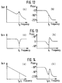
- Figs. 12(a) and 12(b) illustrate the transfer functions of the torque controlling unit 8 and motor 1.
- the figures indicate the relationship between frequency and gain, and between frequency and phase, respectively, wherein the peak of the gain exists at the frequency f p due to machine resonance.
- Figs. 13(a) and 13(b) illustrate the transfer functions of the notch filter 7 having a central frequency f c .
- Figs. 14(a) and 14(b) illustrate the functions after passing through the notch filter 7 to the motor 1 when the resonance frequency f p and the central frequency f c of the notch filter 7 have been adjusted to match each other.
- the peak of the gain due to the machine resonance in Fig. 12(a) and the notch of the gain of the notch filter 7 in Fig. 13(a) offset each other to suppress the machine resonance, thus eliminating the peak from the gain characteristic.
- the gain of the operating/amplifying unit 6 can be raised to enhance the response of the speed control system.
- the adjusted filter coefficient is fixed.
- the resonance frequency f p will not match the central frequency f c of the notch filter 7.
- the suppression of the resonance may not be achieved and the motor control system may become unstable.
- Figs. 15(a) and 15(b) illustrate the characteristics of transmission from the notch filter 7 to the motor 1 at a time when the notch filter 7 central frequency f c is lower than the machine resonance frequency f p .
- the peak of the resonance gain is not suppressed sufficiently and a phase delay value in the low frequency range is increased by the phase delay of the notch filter 7; thus, deteriorating the speed response characteristic, e.g., an overshoot increase.
- Figs. 16(a) and 16(b) illustrate the functions of the transmission from the notch filter 7 to the motor 1 at a time when the notch filter 7 central frequency f c is higher than the machine resonance frequency f p .
- the peak of the resonance gain is not suppressed sufficiently and the phase delay value in the neighborhood of the gain peak is greatly increased by the phase delay of the notch filter 7. This makes the speed control system unstable and may cause oscillation depending on the gain of the operating/amplifying unit 6, leading to a failure of control.
- the filter coefficient defining the characteristic of the notch filter 7 for suppressing the machine resonance may be manually adjusted by an operator on a machine-by-machine basis using an oscilloscope, an FFT analyzer, etc., so that the central frequency f c of the notch filter 7 matches the machine resonance frequency f p .
- This is done in accordance with the speed detection value ⁇ r of the motor 1 at a time when the speed command value ⁇ r * is provided from an external oscillator, or the like.
- this adjustment has the disadvantage that it requires measuring instruments, such as an oscillator and an oscilloscope, as well as much time and skill.
- a motor control circuit is disclosed in Japanese Patent Disclosure Publication No. 46184, wherein the resonance suppression circuit described above is applied to the take-up mechanism of a magnetic tape storage device.
- the resonance filter of the mechanical system varies according to the take-up position (value) of the tape.
- the control circuit is designed to overcome the disadvantage caused by a mismatch of the machine resonance frequency and a notch filter central frequency by changing the central frequency in three stages in accordance with an external signal corresponding to the changes of the machine resonance frequency.
- the central frequency is changed by switching a resistance element, comprising the notch filter, using a short-circuit switch.
- a positioning controller disclosed in the Japanese Patent Disclosure Publication No. 64599 is employed to position the magnetic head of a disc drive using a step motor.
- the positioning controller first detects the vibration of the magnetic head at a time when the magnetic head is moved step by step to vibration detecting tracks provided at specific positions of the inner and outer peripheries of the disc, to select a notch filter on a trial and error basis. This filter will suppress the amplitude of that vibration within a predetermined value from among a plurality of prepared notch filters different in frequency characteristic.
- the vibration characteristic of the step motor varying according to the track position is suppressed by selecting the appropriate notch filter for the tracks divided into three areas: inner periphery, middle and outer periphery. That is, the notch filter selected by the inner periphery vibration detecting track is chosen on the inner peripheral tracks, the notch filter selected by the outer periphery vibration detecting track is chosen on the outer peripheral tracks, and the notch filter representing the characteristic midway between the inner periphery notch filter and the outer periphery notch filter is chosen for the middle tracks.
- a motor speed controller is provided as defined in claim 1.
- Embodiments of the invention are given in claims 2 to 6.
- a filter coefficient setting unit operates to determine a filter coefficient for limiting the passage of the frequency component, and outputs the result to a main filter inserted in any position of the system ranging from the output end of a speed detecting unit to the input end of a torque controlling unit, said main filter limiting the passage of the frequency component in accordance with said filter coefficient entered.
- a reference signal generating unit receives a speed command value and outputs a reference signal having the predetermined bandwidth.
- the adaptive filter receives the reference signal output by said reference signal generating unit and the speed detection value output by a speed detecting unit, operates on the filter coefficient for limiting the passage of the frequency component in accordance with said frequency component superimposed on said speed detection value, and then outputs the result to the main filter.
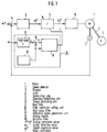
- Fig. 1 is a block diagram of a motor speed controller according to one embodiment of the present invention.
- Fig. 2 is a block diagram of the motor speed controller illustrating a variation of position of the adaptive filter in the main feedback loop according to another embodiment of the present invention.
- Figs. 3 and 4 are block diagrams of a speed controller controlling the speed of a load.
- Fig. 5 is a block diagram of a motdr speed controller according to another embodiment of the present invention.
- Fig. 6 is a block diagram illustrating the basic configuration of an adaptive filter.
- Figs. 7(a) to 7(e) and Figs. 8(a) to 8(c) are graphs indicating the power spectra of various parts and the frequency characteristic of the adaptive filter 16 in the embodiments of the present invention.
- Fig. 9 is a block diagram illustrating one embodiment of the reference signal generating unit 13.
- Fig. 10 is a graph representing the response waveforms of parts of the embodiment shown in Fig. 5.
- Fig. 11 is a block diagram illustrating a motor speed controller known in the art.
- Figs. 12(a) and 12(b) to Figs. 16(a) and 16(b) are charts representing the transmission functions of the elements in Fig. 11.
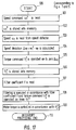
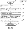
- Figs. 17 - 19 are flowcharts indicating the processing which takes place in a software implementation of Figs. 1 and 5;
- Fig. 20 illustrates an application to a fine-motion table using a piezo-actuator.
- Fig. 1 is a block diagram of a motor speed controller in accordance with one embodiment of the present invention.
- Fig. 1 illustrates a main filter 9 provided for limiting the passage of a frequency component in accordance with an entered filter coefficient f output from a filter coefficient setting unit 10.
- the block representing the filter coefficient setting unit 10 has a high-pass filter 12 provided for passing a frequency component higher than a predetermined frequency in the same region as an entered speed detection value ⁇ r output by a speed detector 2.
- the setting unit 10 further includes a reference signal generating unit 13, adding unit 15, and an adaptive filter 16.
- the reference signal generating unit 13 outputs a reference signal r having frequency components less than the predetermined frequency. This output is sent to adding unit 15 and adaptive filter 16.
- the high-pass filter 12 passes a signal including a resonance frequency component d received from the detector 2.
- the adding unit 15 receives the high-pass filter output and adds it to the reference signal r output from the signal generating unit 13.
- the resultant signal x is output to adaptive filter 16.
- the adaptive filter 16 then, operates on the filter coefficient f to limit the passage of the frequency component d, and outputs the result to main filter 9. It will be appreciated that where the main filter 9 and adaptive filter 16 employ plural coefficients, one or more coefficients may be subject to operation/variation in accordance with the invention. In this specification, for purposes of clarity, the singular term "filter coefficient" is consistently employed, but should be interpreted as covering both the singular and plural cases.
- Fig. 6 is a block diagram illustrating the basic configuration of the adaptive filter 16 having a filter 17 and a filter coefficient adjusting unit 19 for adjusting the filter coefficient of the filter 17.
- Figs. 7(a), 7(b), 7(c), 7(d) and 7(e) indicate the power spectra of the reference signal r, the signal d, input x, output y, and deviation e before adjustment of the filter coefficient f, respectively.
- Figs. 8(a), 8(b) and 8(c) indicate the power spectrum of the output y after adjustment of filter coefficient f, the deviation e, and the frequency characteristic of the filter 17, respectively.
- Fig. 9 is a block diagram illustrating one embodiment of the reference signal generating unit 13, having a random noise generating circuit 30, and a low-pass filter 31 which outputs the reference signal r.
- the cut-off frequency of the high-pass filter 12 in the filter coefficient setting unit 10 has been set to a speed control bandwidth f b .
- the high-pass filter 12 receives a motor speed ⁇ r (i.e. , speed detection value output by the speed detection unit 2) and outputs a machine resonance frequency component d included in that speed ⁇ r .
- the speed control bandwidth f b includes a frequency band at which the gain of a closed-loop transmission function ranging from the speed command to the speed of the motor 1 to be controlled is 1/ 2 times that of a dc gain.
- the speed control bandwidth f b is ordinarily set to less than 1/3 to 1/2 of the machine resonance frequency f p .
- the reference signal generating unit 13 generates the reference signal r including the same frequency components as the speed control bandwidth f b .
- the adder 15 adds the high-pass filter 12 output d and the reference signal r and outputs a signal x.
- the adaptive filter changes its own characteristic to output the most appropriate signal in accordance with the input signal applied; i.e., the filter changes its characteristic according to the quality of the input signal.
- the adaptive filter 16 adjusts its own filter coefficient serially so that its output y is most approximated to the target signal, i.e., reference signal r, in response to the input x.
- the input x includes the reference signal r and the vibration component d caused by machine resonance.
- the adaptive filter 16 adjusts its own filter coefficient to become a filter which passes the component of the frequency band that the reference signal r has, while suppressing other frequency components, here the component d due to machine resonance (i.e., it becomes a notch filter of which the central frequency f c matches the machine resonance frequency f p ).
- the filter coefficient of the main filter 9 is set to the same value as that of the adaptive filter 16 by the signal therefrom so as to have the characteristic of a notch filter.
- the main filter 9 is automatically adjusted to have a characteristic which suppresses the machine resonance frequency component which is the source of vibration due to machine resonance included in the output ⁇ 1* of the operating/amplifying unit 6.
- the input of the adaptive filter 16 is the vibration component d and the target signal is zero (i.e., r is zero)
- a filter which suppresses the vibration component due to machine resonance would in principle be generated according to the operation principle of the adaptive filter 16.
- the filter may have a frequency characteristic which cuts off all frequency components, and it is not ensured that the filter will provide the desired characteristic of-passing the frequency component up to the speed control bandwidth and suppressing the machine resonance frequency component.
- the optimum input of the adaptive filter 16 is the signal x which is the sum of non-zero reference signal r and the vibration component d.
- the filter 17 receives and filters the signal x, and the filter coefficient adjusting unit 19 adjusts the filter coefficient of the filter 17 to reduce the deviation e between the reference signal r and the filter output y output by subtracting unit 18, so that the output y is most approximated to the target signal, i.e., reference signal r.
- a finite impulse response (FIR) filter e.g., a transversal filter or a tapped delay line filter
- IIR infinite impulse response
- a least mean square (LMS) algorithm In the filter coefficient adjusting unit 19, a least mean square (LMS) algorithm, a recursive least square (RLS) algorithm, or the like, can be used.
- LMS least mean square
- RLS recursive least square
- These algorithms are also digital processing techniques and can be-employed with a microprocessor. The operation of, for example, the LMS algorithm will be described briefly.
- the square of the deviation e has a curved surface like a bowl in an (n + 1)-dimensional space with respect to the filter coefficient f and has a single minimum point.
- the LMS algorithm adjusts the filter coefficient at the next sampling by subtracting a variation value proportionate to the gradient of the bowl-shaped curved surface from the filter coefficient at the current sampling in order to converge the square of the deviation e on said minimum point.
- the cut-off frequency of the low-pass filter 31 (Fig. 9) included in the reference signal generating unit 13 is set to the speed control bandwidth f b . Consequently, the power spectrum of the reference signal r has a characteristic of attenuating above the speed control bandwidth f b , as shown in Fig. 7(a), and includes the frequency component up to the speed control bandwidth f b , but does not include the machine resonance frequency component.
- the power spectrum of the high-pass filter 12 output d has a peak at the machine resonance frequency f p , as shown in Fig. 7(b).
- the power spectrum of the signal x i.e ., the sum of the high-pass filter 12 output d and the reference signal r
- the input x of the filter 17 in the adaptive filter 16 includes the reference signal r, which includes the frequency component up to the speed control bandwidth f b
- the high-pass filter 12 output d which is the vibration component due to the machine resonance
- the power spectrum of the output y before filter coefficient adjustment has a waveform similar to the power spectrum of the input x, as shown in Fig. 7(d). Accordingly, the power spectrum of the deviation e between the reference signal r and the output y corresponds to that of the signal d in Fig.
- the main filter 9 is automatically adjusted to be a notch filter of which central frequency f c matches the machine resonance frequency f p .
- the main filter 9 need not be otherwise adjusted to suppress the machine resonance.
- the aforementioned adjustment of the filter coefficient f is made to allow automatic follow-up to the change in machine resonance frequency f p , thereby eliminating the possibility of unstable speed control.
- Fig. 2 is a block diagram of a motor speed controller according to another embodiment of the present invention, wherein the numerals used in Fig. 1 identify identical parts.
- Fig. 1 is different from Fig. 2 in that the main filter 9 of Fig. 2 receives the speed detection value ⁇ r of the motor 1 detected by the speed detector 2.
- the main filter 9 filters and outputs the speed detection value ⁇ r1
- the operating/amplifying unit 6 receives the deviation between the speed command value ⁇ r *, i.e ., the output of the subtracter 5, and the output ⁇ r1 of the main filter 9.
- the unit 6 outputs to the torque controlling unit 8 the torque command value ⁇ 1* which will reduce that deviation ⁇ r * - ⁇ r1 .
- the main filter 9 receives the filter coefficient f output by the filter coefficient setting unit 10 and is automatically adjusted to be a notch filter which suppresses the machine resonance frequency component. Therefore, the machine resonance frequency component is removed from ⁇ r1 and there is no possibility that after comparison with the speed command value ⁇ r * by the subtracter 8, ⁇ r1 will be amplified by the operating/amplifying unit 6 and cause vibration.
- Fig. 3 is a block diagram of a motor speed controller according to an arrangement, wherein a speed detector 2A is provided for detecting the speed ⁇ r of the load 4 (as opposed to the detection of speed of the motor achieved in the previous embodiments).
- the arrangement shown in Fig. 3 performs similar operation and has a similar effect to the one illustrated in Fig. 1, except that the speed detector 2A is provided in the load 4 for detecting and controlling the speed of the load 4.
- Fig. 4 is a block diagram of a motor speed controller according to another arrangement.
- the arrangement shown in Fig. 4 performs similar operation and produces a similar result as the one illustrated in Fig. 2, except that the speed detector 2A is provided in the load 4 for detecting and controlling the speed of the load 4.
- Fig. 5 is a block diagram of a motor speed controller according to another embodiment of the present invention, comprising a filter coefficient setting unit 11 and reference signal generating unit 14.
- the filter coefficient setting unit 11 is different from the filter coefficient setting unit 10 (shown in Fig. 1) in that the reference signal generating unit 14 receives the speed command value ⁇ r * and generates the reference signal r having almost the same bandwidth f b as that of the speed control system in response to the speed command value ⁇ r *.
- the adaptive filter 16 outputs the filter coefficient f in response to the input of said reference signal r and the speed detection value ⁇ r .
- the speed controller is substantially the same in configuration and operation as the one shown in Fig. 1.
- Fig. 10 shows response waveforms of the reference signal r, the motor speed ⁇ r , the output y of the adaptive filter 16, shown in Fig. 6, and the deviation e between the reference signal r and the output y, which are obtained at a time when the speed command value ⁇ r * is changed.
- the motor speed detecting value ⁇ r overlaps (is superimposed on) a response component to the speed command value ⁇ r * and a vibration component due to the machine resonance independent of that response component.
- the reference signal ⁇ r Since the reference signal ⁇ r is pre-adjusted as described previously to be in almost the same bandwidth as that of the speed control system, the reference signal r has almost the same waveform as that of the response component of the motor speed ⁇ r (excluding the reference value and the vibration component), as can be seen by comparing indicated by the waveforms of ⁇ r and r. As indicated by the waveform y, the output y of the adaptive filter 16 has a similar waveform to that of ⁇ r before the filter coefficient f is adjusted. Hence, the waveform of the deviation e between the reference signal r and the output y develops a waveform equivalent to the vibration component included in the motor speed ⁇ r .
- the filter coefficient adjusting unit 19 (Fig. 6) adjusts the filter coefficient f sequentially to reduce the deviation e so that the output y is approximated to the reference signal r. Accordingly, since the filter 17 has the characteristic of a notch filter which only suppresses the vibration component caused by machine resonance at the time when the deviation e is fully reduced after the adjustment of the filter coefficient f, the vibration component disappears from the motor speed ⁇ r and the output y. Furthermore, because the filter coefficient f of the main filter 9 is set to the same value as that of the filter 17 in the adaptive filter 16, the main filter 9 is automatically adjusted to be a notch filter of which central frequency f c matches the machine resonance frequency f p . Thus, the main filter 9 is automatically adjusted to suppress the machine resonance. Moreover, if the machine resonance frequency f p has changed, the aforementioned adjustment process is repeated so that the main filter 9 is automatically adjusted to have a notch filter characteristic corresponding to the machine resonance frequency f p .
- the reference signal generating unit 14 has a first order lag element of a time constant T1 represented by a transmission function in expression (1).
- T1 may be set so that the reference signal r has almost the same response in the bandwidth of the speed control system as the speed command value ⁇ r *.
- r 1 1+ sT 1 ⁇ r * where s is a differential operator.
- the first order lag element may be replaced by a second order lag element or the like which has been adjusted to have almost the same response to the speed control.
- the cut-off frequency of the low-pass filter 31 set to the speed control bandwidth f b in the block diagram of the reference signal generating unit 13 may be defined between f b and f p because any frequency component less than the machine resonance frequency f p may be included in the reference signal r.
- the high-pass filter 12 of which cut-off frequency has been set to the speed control bandwidth may be a band-pass filter, or the like, that has a characteristic where the low-range cut-off frequency has been set in the vicinity of the speed control bandwidth and the high-range cut-off frequency has been set to a higher value than the machine resonance frequency. This is because the machine resonance frequency component included in the speed ⁇ r of the motor 1, or the load 4, may be mainly detected by the high-pass filter 12.
- the random noise generating unit 30 may be replaced by a rectangular wave generating circuit or a triangular wave generating circuit, in which case harmonic components included in the rectangular wave or the triangular wave should be set so that many harmonic components are included at less than the cut-off frequency of the low-pass filter 31.
- the torque controlling unit 8 may be directly controlled by, for example, a current, a voltage of a magnetic flux of the motor 1, or a combination of the two if that controls the torque of the motor 1.
- the output of the operating/amplifying unit 6 need not indicate the torque directly and may be, for example, a current, a voltage, a magnetic flux, or the like, of the motor 1 if such controls the torque of the motor 1.
- the shaft directly connecting the motor 1 and the load 4 may be replaced by gears, a belt and pulleys, a ballscrew and nuts, or a combination of such elements.
- the shaft of the motor 1 may be regarded as a coupler, and if the rigidity of the load 4 is small, the load 4 may be regarded as comprising a coupler to a new load.
- Fig. 17 indicates an operation flowchart with the exception of the operation of the filter coefficient setting units 10 and 11 shown in Figs. 1 and 5, respectively.
- the filter coefficient f Since the filter coefficient f is operated on, stored into the memory (not illustrated), and updated serially by the execution of the operation shown in Fig. 18 or 19, the filter coefficient f is read from memory at step 107 and filtering is executed at step 108.
- Fig. 20 illustrates an embodiment as applied to a fine-motion table positioning device employing a piezo-actuator for use with semiconductor equipment, etc.
- a piezo-actuator 101 is fixed at one end and secured to a fine-motion table 102 at the other end.
- the piezo-actuator 101 stretches in the x direction in accordance with a voltage applied by a drive amplifier 100 to drive the fine-motion table 102 supported by a flexible support rod 103 and a workpiece mounted thereon.
- the displacement x of the fine-motion table 102 is detected and compared with a command value x* by a displacement detector 105 and a voltage command V1* is output by operation/amplifying unit 6 so that their deviation is zeroed.
- V1* is filtered by a main filter 9 and output to the drive amplifier 100 as a new voltage command V2*.
- the fine-motion table 102 is supported by the flexible support rod 103 to avoid the problem of friction which influences positioning accuracy.
- said flexible support rod 103, fine-motion table 102, and workpiece constitute a machine resonance system
- an attempt to position the fine-motion table 102 on a high-speed/rapid response basis for improved production efficiency causes vibration to occur due to machine resonance and, in addition, causes a resonance frequency to change in accordance with a change in workpiece weight.
- An advantage of the embodiment the present invention is that the filter coefficient of the main filter 9 is automatically set, as appropriate, by filter coefficient setting unit 10 to restrict the passage of a machine resonance frequency component, so that vibration does not occur if an attempt to position the fine-motion table 102 is made.
- a filter coefficient setting unit operates on the filter coefficient relatively accurately and outputs the operation result to the main filter to suppress the resonance of said mechanical system.
Landscapes
- Engineering & Computer Science (AREA)
- Power Engineering (AREA)
- Human Computer Interaction (AREA)
- Manufacturing & Machinery (AREA)
- Physics & Mathematics (AREA)
- General Physics & Mathematics (AREA)
- Automation & Control Theory (AREA)
- Control Of Electric Motors In General (AREA)
- Feedback Control In General (AREA)
Claims (6)
- Motordrehzahl-Steuervorrichtung zum Steuern eines mechanischen Systems, das einen Motor und eine davon angetriebene Last aufweist, wobei die Steuervorrichtung folgendes aufweist:eine erste Subtrahiereinrichtung (5), um einen Motordrehzahl-Betriebswert (ωr) von einem Motordrehzahl-Führungswert (ωr*) zu subtrahieren und ein resultierendes Signal als ein Steuersignal (τ₁*) abzugeben, um den Betrieb des Motors (1) zu steuern;ein Hauptfilter (9), das funktionsmäßig mit der ersten Subtrahiereinrichtung (5) gekoppelt ist, um ein Drehmomentführungssignal (τ₂*), das aus dem Steuersignal (τ₁*) erhalten ist, nach Maßgabe eines vorgegebenen Filterkoeffizienten (f) durchzulassen; undeine Filterkoeffizient-Vorgabeeinrichtung (10), die mit dem Hauptfilter (9) gekoppelt ist und ein adaptives Filter (16) aufweist, um den Filterkoeffizienten (f) vorzugeben und den Koeffizienten an das Hauptfilter (9) abzugeben,die Filterkoeffizient-Vorgabeeinrichtung (10) ferner folgendes aufweist:
gekennzeichnet dadurch , daß- eine Hochpaßfiltereinrichtung (12), um den Motordrehzahl-Betriebswert (ωr) zu empfangen und Frequenzkomponenten (d), die höher als eine vorbestimmte Frequenz (fb) sind, durchzulassen;- eine Referenzsignalerzeugungseinrichtung (13), um ein Referenzsignal (r) zu erzeugen, das Frequenzkomponenten hat, die niedriger als die vorbestimmte Frequenz (fb) sind;- eine Addiereinrichtung (15), um das Referenzsignal (r) zu den von der Hochpaßfiltereinrichtung (12) durchgelassenen Frequenzkomponenten (d) zu addieren und ein resultierendes Signal (x) abzugeben;- wobei das adaptive Filter (16) das Referenzsignal (r) und das resultierende Signal (x) empfängt und den Filterkoeffizienten (f) bestimmt, um den Durchgang der von der Hochpaßfiltereinrichtung (12) durchgelassenen Frequenzkomponenten (d) selektiv zu begrenzen. - Motordrehzahl-Steuervorrichtung nach Anspruch 1, wobei das adaptive Filter (16) folgendes aufweist:eine Filtereinrichtung (17), um das von der Addiereinrichtung (15) abgegebene resultierende Signal (x) zu empfangen und ein Ausgangssignal zu erzeugen, das den Durchgang der Frequenzkomponenten (d), die höher als die vorbestimmte Frequenz (fb) sind, selektiv begrenzt;eine zweite Subtrahiereinrichtung (18), um das Ausgangssignal der Filtereinrichtung (17) von dem Referenzsignal (r) zu subtrahieren und ein resultierendes Signal abzugeben; undeine Filterkoeffizient-Einstelleinrichtung (19), die mit der zweiten Subtrahiereinrichtung (18) gekoppelt ist, um den Filterkoeffizienten der Filtereinrichtung (17) einzustellen und den Filterkoeffizienten (f) an das Hauptfilter (9) abzugeben.
- Motordrehzahl-Steuervorrichtung nach Anspruch 2, die ferner folgendes aufweist:eine Verstärkungseinrichtung (6), die mit dem Hauptfilter (9) gekoppelt ist, um das von der ersten Subtrahiereinrichtung (5) abgegebene resultierende Signal zu verstärken; undeine Drehmomentsteuereinrichtung (8), die mit dem Hauptfilter (9) gekoppelt ist, um das von dem Hauptfilter (9) durchgelassene Drehmoment-Führungssignal (τ₂*) zu empfangen und das Drehmoment des Motors (1) nach Maßgabe dieses Drehmoment-Führungssignals zu steuern.
- Motordrehzahl-Steuervorrichtung nach Anspruch 2, die ferner folgendes aufweist:eine Verstärkungseinrichtung (6), die mit der ersten Subtrahiereinrichtung (5) gekoppelt ist, um das von der ersten Subtrahiereinrichtung (5) abgegebene resultierende Signal zu verstärken; undeine Drehmomentsteuereinrichtung (8), die mit der Verstärkungseinrichtung (6) gekoppelt ist, um das von dem Hauptfilter (9) durchgelassene Drehmoment-Führungssignal (τ₂*) zu empfangen und das Drehmoment des Motors (1) nach Maßgabe dieses Drehmoment-Führungssignals ( τ₂*) zu steuern, wobei das Hauptfilter (9) mit der ersten Subtrahiereinrichtung (5) gekoppelt ist und Rückmeldung als den Motordrehzahl-Betriebswert (ωr) von dem Motor (1) empfängt.
- Motordrehzahl-Steuervorrichtung nach einem der Ansprüche 1 bis 4, wobei die Referenzsignalerzeugungseinrichtung (13) den Motordrehzahl-Führungswert (ωr*) empfängt.
- Motordrehzahl-Steuervorrichtung nach einem der Ansprüche 3, 4 oder 5, wobei das Hauptfilter (9) an irgendeiner Position eines geschlossenen Regelkreises eingefügt ist, der von dem Ausgangsende einer mit dem Motor (1) verbundenen Motordrehzahl-Detektiereinrichtung (2) bis zu dem Eingangsende der Drehmomentsteuereinrichtung (8) reicht.
Applications Claiming Priority (2)
| Application Number | Priority Date | Filing Date | Title |
|---|---|---|---|
| JP2204720A JP2504307B2 (ja) | 1990-08-01 | 1990-08-01 | 電動機の速度制御装置 |
| JP204720/90 | 1990-08-01 |
Publications (2)
| Publication Number | Publication Date |
|---|---|
| EP0469617A1 EP0469617A1 (de) | 1992-02-05 |
| EP0469617B1 true EP0469617B1 (de) | 1996-01-17 |
Family
ID=16495196
Family Applications (1)
| Application Number | Title | Priority Date | Filing Date |
|---|---|---|---|
| EP91112973A Expired - Lifetime EP0469617B1 (de) | 1990-08-01 | 1991-08-01 | System bestehend aus einem geschlossenen Regelkreis mit einem adaptiven Filter |
Country Status (6)
| Country | Link |
|---|---|
| US (1) | US5404418A (de) |
| EP (1) | EP0469617B1 (de) |
| JP (1) | JP2504307B2 (de) |
| KR (1) | KR940009206B1 (de) |
| DE (1) | DE69116461T2 (de) |
| HK (1) | HK1007039A1 (de) |
Cited By (1)
| Publication number | Priority date | Publication date | Assignee | Title |
|---|---|---|---|---|
| EP2124116A1 (de) | 2008-05-21 | 2009-11-25 | Hexagon Metrology GmbH | Verfahren zur Steuerung eines CNC-gesteuerten Koordinatenmessgerätes sowie Koordinatenmessgerät |
Families Citing this family (66)
| Publication number | Priority date | Publication date | Assignee | Title |
|---|---|---|---|---|
| JP2840139B2 (ja) * | 1991-04-24 | 1998-12-24 | ファナック株式会社 | 予見繰り返し制御装置 |
| JP2744731B2 (ja) * | 1992-05-07 | 1998-04-28 | 山洋電気株式会社 | サーボ系のノッチフィルタ自動調整方法及び装置 |
| JPH06253564A (ja) * | 1993-02-25 | 1994-09-09 | Ckd Corp | モータ共振周波数減衰用フィルタの定数値設定方法 |
| EP1674974A3 (de) * | 1994-06-07 | 2007-03-21 | Hitachi, Global Storage Technologies Japan, Ltd. | Gerät zum Speichern von Information |
| US5589746A (en) * | 1994-11-10 | 1996-12-31 | Seagate Technology, Inc. | Brushless motor speed control arrangement having derived common mode supply signal component |
| US5642461A (en) * | 1994-11-14 | 1997-06-24 | Seagate Technology, Inc. | Economical wide range speed control system |
| US5548192A (en) * | 1995-06-14 | 1996-08-20 | Hewlett-Packard Company | Adaptive feedback system for controlling head/arm position in a disk drive |
| DE19710268A1 (de) * | 1997-03-13 | 1998-09-24 | Heidenhain Gmbh Dr Johannes | Verfahren zur Bearbeitung eines Werkstücks mit maximaler Bearbeitungsgeschwindigkeit |
| JP3111046B2 (ja) * | 1997-09-24 | 2000-11-20 | インターナショナル・ビジネス・マシーンズ・コーポレ−ション | 周波数特性導出方法及び装置、ノッチフィルタ設定方法及び装置、ノッチフィルタ調整方法、制御装置、並びにディスク記憶装置 |
| US6046560A (en) * | 1998-03-20 | 2000-04-04 | Trw Inc. | Electric assist steering system having an improved motor current controller with gain scheduler |
| US6107767A (en) * | 1998-03-20 | 2000-08-22 | Trw Inc. | Electric assist steering system having an improved motor current controller with notch filter |
| US6196345B1 (en) * | 1998-05-18 | 2001-03-06 | Bae Systems Controls, Inc. | Drive-line damping control for an electric vehicle |
| JP2003523035A (ja) * | 1998-06-26 | 2003-07-29 | シーゲイト テクノロジー エルエルシー | ディスク・ドライブ・サーボで使用される改良ノッチ・フィルタリング |
| DE19846637A1 (de) | 1998-10-09 | 2000-04-13 | Heidenhain Gmbh Dr Johannes | Verfahren und Schaltungsanordnung zur automatischen Parametrierung eines schnellen digitalen Drehzahlregelkreises |
| US6240246B1 (en) | 1998-10-30 | 2001-05-29 | Alliedsignal, Inc. | Anti-resonance mixing filter |
| US20020178321A1 (en) * | 1998-11-25 | 2002-11-28 | Philip J. Calamatas | Programmable system including self locking memory circuit for a tristate data bus |
| JP2000322105A (ja) * | 1999-05-07 | 2000-11-24 | Toshiba Mach Co Ltd | サーボ制御装置およびサーボ制御装置の安定化調整方法 |
| EP1226476B1 (de) | 1999-09-08 | 2004-04-07 | Dr. Johannes Heidenhain GmbH | Verfahren und schaltungsanordnung zur erzeugung von lagesollwerten für einen lageregelkreis einer numerisch bahngesteuerten maschine |
| US6445152B1 (en) * | 1999-11-24 | 2002-09-03 | Westinghouse Air Brake Co. | Door control system |
| US6741417B2 (en) * | 2000-08-30 | 2004-05-25 | Seagate Technology Llc | Plant variation compensation for piezoelectric microactuator in dual-stage servo of disc drives |
| US6710965B2 (en) | 2001-10-02 | 2004-03-23 | Seagate Technology Llc | Phase-advanced filter for robust resonance cancellation |
| NL1019715C2 (nl) * | 2002-01-09 | 2003-07-11 | Tno | Inrichting en werkwijze voor het verminderen van geluid. |
| JP2003228422A (ja) * | 2002-02-04 | 2003-08-15 | Canon Inc | ステージ制御装置及び露光装置並びにデバイスの製造方法 |
| DE10217707A1 (de) * | 2002-04-17 | 2003-11-06 | Heidelberger Druckmasch Ag | Kompensation von Zylinderschwingungen in bedruckstoffverarbeitenden Maschinen |
| US6789641B2 (en) * | 2002-08-14 | 2004-09-14 | Trw Inc. | Method and apparatus for controlling an electric assist motor using a modified blending filter |
| JP2004086702A (ja) * | 2002-08-28 | 2004-03-18 | Yaskawa Electric Corp | 振動抑制フィルタの自動設定方法 |
| US6963184B2 (en) * | 2002-09-26 | 2005-11-08 | 3M Innovative Properties Company | Adaptable spatial notch filter |
| DE10246093C1 (de) * | 2002-10-02 | 2003-11-27 | Siemens Ag | Verfahren zur Dämpfung mechanischer Schwingungen von Achsen von Werkzeugmaschinen, Produktionsmaschinen oder Robotern |
| WO2004049550A1 (ja) * | 2002-11-26 | 2004-06-10 | Mitsubishi Denki Kabushiki Kaisha | モータの速度制御装置 |
| ATE396439T1 (de) * | 2002-12-18 | 2008-06-15 | Koninkl Philips Electronics Nv | Wiederholsteuerung und servoantriebssystem damit |
| US8639122B2 (en) * | 2004-07-02 | 2014-01-28 | Finisar Corporation | Filtering digital diagnostics information in an optical transceiver prior to reporting to host |
| DE102004038370B4 (de) * | 2004-08-06 | 2009-06-25 | Austriamicrosystems Ag | Adaptive Regelvorrichtung, Verwendung der Regelvorrichtung, Sensor mit einer derartigen Regelvorrichtung und adaptives Verfahren zur Selbstkompensation von Störsignalen eines Sensors |
| WO2006105677A2 (de) * | 2005-04-07 | 2006-10-12 | Belimo Holding Ag | Unterdrückung von schwingungen |
| US7109670B1 (en) * | 2005-05-25 | 2006-09-19 | Rockwell Automation Technologies, Inc. | Motor drive with velocity-second compensation |
| US7187142B2 (en) * | 2005-05-25 | 2007-03-06 | Rockwell Automation Technologies, Inc. | Motor drive with velocity noise filter |
| JP2007202348A (ja) * | 2006-01-27 | 2007-08-09 | Fuji Electric Fa Components & Systems Co Ltd | 電動機の制御装置 |
| JP4569514B2 (ja) * | 2006-04-25 | 2010-10-27 | 株式会社安川電機 | 適応ノッチフィルタ |
| EP1857902A1 (de) * | 2006-05-18 | 2007-11-21 | Saab Ab | Verfahren und Vorrichtung zur Regelung des Spieles |
| ATE546877T1 (de) * | 2006-05-18 | 2012-03-15 | Busch Dieter & Co Prueftech | Elektrischer antrieb sowie verfahren zum steuern eines solchen antriebs |
| JP4174543B2 (ja) | 2007-01-29 | 2008-11-05 | ファナック株式会社 | サーボモータの制御装置 |
| TW200849231A (en) * | 2007-02-09 | 2008-12-16 | Koninkl Philips Electronics Nv | Noise reduction |
| JP4314639B2 (ja) * | 2007-04-06 | 2009-08-19 | 村田機械株式会社 | 搬送装置 |
| DE102008048406A1 (de) * | 2007-10-17 | 2009-04-23 | Heidelberger Druckmaschinen Ag | Vorrichtung zur Steuerung einer Bogenrotationsdruckmaschine mit mehreren Antriebsmotoren |
| US8027119B2 (en) * | 2007-11-07 | 2011-09-27 | Seagate Technology Llc | Vibration detection and compensation filter |
| JP5159463B2 (ja) * | 2008-06-20 | 2013-03-06 | 三菱電機株式会社 | 電動機の位置決め制御装置 |
| CN101620436A (zh) * | 2008-07-04 | 2010-01-06 | 鸿富锦精密工业(深圳)有限公司 | 后加减速控制装置和后加减速控制方法 |
| FR2945079A1 (fr) * | 2009-04-29 | 2010-11-05 | Peugeot Citroen Automobiles Sa | Procede de controle du fonctionnement d'un moteur |
| JP5226617B2 (ja) * | 2009-06-27 | 2013-07-03 | エイチジーエスティーネザーランドビーブイ | ディスク・ドライブ及びそのサーボ制御方法 |
| JP5561468B2 (ja) * | 2010-02-03 | 2014-07-30 | 西芝電機株式会社 | 船舶用電気推進装置のインバータシステム |
| JP5621274B2 (ja) * | 2010-02-25 | 2014-11-12 | 株式会社明電舎 | モータのトルク制御装置 |
| FR2967508B1 (fr) * | 2010-11-16 | 2014-02-21 | Ixmotion | Procede et dispositif de controle actif de vibrations mecaniques par mise en oeuvre d'une loi de controle constituee d'un correcteur central et d'un parametre de youla |
| GB2490493B (en) * | 2011-04-28 | 2013-04-17 | Sevcon Ltd | Motor controller with oscillation damping system |
| KR101987092B1 (ko) | 2011-04-28 | 2019-06-10 | 세브콘 리미티드 | 전기 모터 및 모터 제어기 |
| JP5324623B2 (ja) | 2011-06-24 | 2013-10-23 | 本田技研工業株式会社 | 車両用駆動制御装置 |
| JP5384608B2 (ja) * | 2011-12-13 | 2014-01-08 | 東芝機械株式会社 | サーボ制御装置およびその調整方法 |
| JP6222834B2 (ja) * | 2014-01-16 | 2017-11-01 | 日立オートモティブシステムズ株式会社 | モータ制御装置 |
| JP6163135B2 (ja) * | 2014-05-30 | 2017-07-12 | 日立オートモティブシステムズ株式会社 | モータ制御装置 |
| CN103986404B (zh) * | 2014-06-04 | 2016-03-30 | 哈尔滨工业大学 | 用于信号重构的方法和装置 |
| CN104192528B (zh) * | 2014-08-12 | 2017-03-15 | 北京天拓四方科技有限公司 | 一种胶带机停车时抱闸的控制方法 |
| ITUB20159358A1 (it) * | 2015-12-22 | 2017-06-22 | Faiveley Transport Italia Spa | Procedimento per il controllo e il recupero dell'aderenza delle ruote di un assile controllato di un veicolo ferroviario. |
| WO2017208701A1 (ja) | 2016-05-31 | 2017-12-07 | 三菱電機株式会社 | モータ制御装置 |
| US9912266B2 (en) | 2016-08-02 | 2018-03-06 | Otis Elevator Company | Motor torque ripple reduction using DC bus harmonics |
| WO2018230253A1 (ja) * | 2017-06-15 | 2018-12-20 | パナソニックIpマネジメント株式会社 | 電動機制御装置、及び電動機制御方法 |
| CN110114184B (zh) * | 2017-10-19 | 2021-09-03 | 三菱电机株式会社 | 激光加工机及激光加工系统 |
| JP6841801B2 (ja) * | 2018-08-30 | 2021-03-10 | ファナック株式会社 | 機械学習装置、制御システム及び機械学習方法 |
| CN113890453B (zh) * | 2020-04-08 | 2024-11-01 | 高创传动科技开发(深圳)有限公司 | 伺服系统及其谐振抑制方法 |
Family Cites Families (12)
| Publication number | Priority date | Publication date | Assignee | Title |
|---|---|---|---|---|
| US4035805A (en) * | 1975-07-23 | 1977-07-12 | Scientific-Atlanta, Inc. | Satellite tracking antenna system |
| GB1577132A (en) * | 1976-03-19 | 1980-10-22 | Rca Corp | Compensation apparatus for a servo system with periodic command signals |
| US5027047A (en) * | 1982-09-13 | 1991-06-25 | Westinghouse Electric Corp. | Half angle mechanism for a heliostat |
| JPS61146184A (ja) * | 1984-12-19 | 1986-07-03 | Green Cross Corp:The | ウロキナ−ゼの製造方法 |
| US4804894A (en) * | 1986-06-10 | 1989-02-14 | Sony Corporation | Motor rotation servo control apparatus |
| JPS6464599A (en) * | 1987-09-02 | 1989-03-10 | Brother Ind Ltd | Positioning controller |
| JPH0820905B2 (ja) * | 1988-03-10 | 1996-03-04 | 富士通株式会社 | サーボ位置決め装置 |
| JP2615392B2 (ja) * | 1988-03-31 | 1997-05-28 | 工業技術院長 | 工具微動台 |
| JPH01304511A (ja) * | 1988-06-02 | 1989-12-08 | Seiko Instr Inc | サーボ制御装置 |
| US5032776A (en) * | 1988-11-10 | 1991-07-16 | Unisys Corp. | Attenuation filter |
| US4947093A (en) * | 1988-11-25 | 1990-08-07 | Micropolis Corporation | Shock resistant winchester disk drive |
| US4912387A (en) * | 1988-12-27 | 1990-03-27 | Westinghouse Electric Corp. | Adaptive noise cancelling for magnetic bearing auto-balancing |
-
1990
- 1990-08-01 JP JP2204720A patent/JP2504307B2/ja not_active Expired - Lifetime
-
1991
- 1991-07-24 KR KR1019910012717A patent/KR940009206B1/ko not_active Expired - Fee Related
- 1991-07-31 US US07/738,643 patent/US5404418A/en not_active Expired - Lifetime
- 1991-08-01 EP EP91112973A patent/EP0469617B1/de not_active Expired - Lifetime
- 1991-08-01 DE DE69116461T patent/DE69116461T2/de not_active Expired - Lifetime
-
1998
- 1998-06-23 HK HK98106225A patent/HK1007039A1/en not_active IP Right Cessation
Cited By (1)
| Publication number | Priority date | Publication date | Assignee | Title |
|---|---|---|---|---|
| EP2124116A1 (de) | 2008-05-21 | 2009-11-25 | Hexagon Metrology GmbH | Verfahren zur Steuerung eines CNC-gesteuerten Koordinatenmessgerätes sowie Koordinatenmessgerät |
Also Published As
| Publication number | Publication date |
|---|---|
| EP0469617A1 (de) | 1992-02-05 |
| KR920005445A (ko) | 1992-03-28 |
| DE69116461D1 (de) | 1996-02-29 |
| JP2504307B2 (ja) | 1996-06-05 |
| DE69116461T2 (de) | 1996-09-12 |
| JPH0491689A (ja) | 1992-03-25 |
| US5404418A (en) | 1995-04-04 |
| HK1007039A1 (en) | 1999-03-26 |
| KR940009206B1 (ko) | 1994-10-01 |
Similar Documents
| Publication | Publication Date | Title |
|---|---|---|
| EP0469617B1 (de) | System bestehend aus einem geschlossenen Regelkreis mit einem adaptiven Filter | |
| HK1007039B (en) | Closed-loop feedback control system having an adaptive filter | |
| US6274994B2 (en) | Servo control apparatus | |
| JPH01230109A (ja) | サーボ位置決め装置 | |
| EP1026818B1 (de) | Motorgeschwindigkeitsregler und verfahren zur einstellung der verstärkung des reglers | |
| US5589748A (en) | Position control system and position control method thereof | |
| EP0680138A2 (de) | Geschwindigkeitssteuerungsgerät für einen Motor | |
| Ellis et al. | Cures for low-frequency mechanical resonance in industrial servo systems | |
| US6274995B1 (en) | Method and circuit arrangement for automatically parameterizing a quick-acting digital speed control loop | |
| JPH05122970A (ja) | モータ速度制御装置 | |
| US6236182B1 (en) | Method and circuit arrangement for determining an optimum gain for the integrator of a speed controller | |
| JP3633210B2 (ja) | Svc装置の制御方式 | |
| US20010000297A1 (en) | Biquad notch filter | |
| JPH0738127B2 (ja) | ロバスト制御装置 | |
| JP4452367B2 (ja) | 位置制御装置 | |
| JP3337826B2 (ja) | オープンループ振動抑制方法 | |
| JPH0326927B2 (de) | ||
| FI89318C (fi) | Foerfarande foer filtrering av hastighetsaoterkopplingssignal | |
| JPH08168281A (ja) | 電動機ねじり振動抑制制御方法 | |
| JP2658976B2 (ja) | モータの速度制御方式 | |
| JPH0697823A (ja) | 位置制御装置 | |
| JP3173031B2 (ja) | ロボットアームのサーボ制御装置 | |
| US20020041458A1 (en) | Reproducing apparatus capable of controlling amplitude and phase characteristics of reproduced signals | |
| JP3241264B2 (ja) | アクティブ騒音抑制制御方法 | |
| JPH0740268A (ja) | ロボットアームの制御装置 |
Legal Events
| Date | Code | Title | Description |
|---|---|---|---|
| PUAI | Public reference made under article 153(3) epc to a published international application that has entered the european phase |
Free format text: ORIGINAL CODE: 0009012 |
|
| AK | Designated contracting states |
Kind code of ref document: A1 Designated state(s): DE FR GB |
|
| 17P | Request for examination filed |
Effective date: 19920326 |
|
| 17Q | First examination report despatched |
Effective date: 19940318 |
|
| GRAA | (expected) grant |
Free format text: ORIGINAL CODE: 0009210 |
|
| AK | Designated contracting states |
Kind code of ref document: B1 Designated state(s): DE FR GB |
|
| REF | Corresponds to: |
Ref document number: 69116461 Country of ref document: DE Date of ref document: 19960229 |
|
| ET | Fr: translation filed | ||
| PLBE | No opposition filed within time limit |
Free format text: ORIGINAL CODE: 0009261 |
|
| STAA | Information on the status of an ep patent application or granted ep patent |
Free format text: STATUS: NO OPPOSITION FILED WITHIN TIME LIMIT |
|
| 26N | No opposition filed | ||
| REG | Reference to a national code |
Ref country code: GB Ref legal event code: 746 Effective date: 19971202 |
|
| REG | Reference to a national code |
Ref country code: FR Ref legal event code: D6 |
|
| REG | Reference to a national code |
Ref country code: GB Ref legal event code: IF02 |
|
| PGFP | Annual fee paid to national office [announced via postgrant information from national office to epo] |
Ref country code: GB Payment date: 20050727 Year of fee payment: 15 |
|
| GBPC | Gb: european patent ceased through non-payment of renewal fee |
Effective date: 20060801 |
|
| PG25 | Lapsed in a contracting state [announced via postgrant information from national office to epo] |
Ref country code: GB Free format text: LAPSE BECAUSE OF NON-PAYMENT OF DUE FEES Effective date: 20060801 |
|
| PGFP | Annual fee paid to national office [announced via postgrant information from national office to epo] |
Ref country code: FR Payment date: 20100824 Year of fee payment: 20 Ref country code: DE Payment date: 20100728 Year of fee payment: 20 |
|
| REG | Reference to a national code |
Ref country code: DE Ref legal event code: R071 Ref document number: 69116461 Country of ref document: DE |
|
| REG | Reference to a national code |
Ref country code: DE Ref legal event code: R071 Ref document number: 69116461 Country of ref document: DE |
|
| PG25 | Lapsed in a contracting state [announced via postgrant information from national office to epo] |
Ref country code: DE Free format text: LAPSE BECAUSE OF EXPIRATION OF PROTECTION Effective date: 20110802 |