EP0469715A1 - Wechselgetriebe mit mindestens zwei Zahnräder aufweisender Vorgelegewelle - Google Patents
Wechselgetriebe mit mindestens zwei Zahnräder aufweisender Vorgelegewelle Download PDFInfo
- Publication number
- EP0469715A1 EP0469715A1 EP91305833A EP91305833A EP0469715A1 EP 0469715 A1 EP0469715 A1 EP 0469715A1 EP 91305833 A EP91305833 A EP 91305833A EP 91305833 A EP91305833 A EP 91305833A EP 0469715 A1 EP0469715 A1 EP 0469715A1
- Authority
- EP
- European Patent Office
- Prior art keywords
- gear
- teeth
- gear teeth
- shaft
- spline
- Prior art date
- Legal status (The legal status is an assumption and is not a legal conclusion. Google has not performed a legal analysis and makes no representation as to the accuracy of the status listed.)
- Granted
Links
- 230000005540 biological transmission Effects 0.000 title description 10
- 230000004323 axial length Effects 0.000 claims description 14
- 238000003754 machining Methods 0.000 description 16
- 230000008901 benefit Effects 0.000 description 3
- 238000005520 cutting process Methods 0.000 description 3
- 235000008526 Galium odoratum Nutrition 0.000 description 2
- 230000000694 effects Effects 0.000 description 2
- 238000004519 manufacturing process Methods 0.000 description 2
- 244000186140 Asperula odorata Species 0.000 description 1
- 244000258271 Galium odoratum Species 0.000 description 1
- 230000009471 action Effects 0.000 description 1
- 150000001875 compounds Chemical class 0.000 description 1
- 238000009826 distribution Methods 0.000 description 1
- 230000006872 improvement Effects 0.000 description 1
- 230000013011 mating Effects 0.000 description 1
- 238000012986 modification Methods 0.000 description 1
- 230000004048 modification Effects 0.000 description 1
- 230000000750 progressive effect Effects 0.000 description 1
- 230000008707 rearrangement Effects 0.000 description 1
- 238000005096 rolling process Methods 0.000 description 1
- 238000007493 shaping process Methods 0.000 description 1
Images


Classifications
-
- F—MECHANICAL ENGINEERING; LIGHTING; HEATING; WEAPONS; BLASTING
- F16—ENGINEERING ELEMENTS AND UNITS; GENERAL MEASURES FOR PRODUCING AND MAINTAINING EFFECTIVE FUNCTIONING OF MACHINES OR INSTALLATIONS; THERMAL INSULATION IN GENERAL
- F16H—GEARING
- F16H57/00—General details of gearing
- F16H57/0018—Shaft assemblies for gearings
- F16H57/0025—Shaft assemblies for gearings with gearing elements rigidly connected to a shaft, e.g. securing gears or pulleys by specially adapted splines, keys or methods
-
- F—MECHANICAL ENGINEERING; LIGHTING; HEATING; WEAPONS; BLASTING
- F16—ENGINEERING ELEMENTS AND UNITS; GENERAL MEASURES FOR PRODUCING AND MAINTAINING EFFECTIVE FUNCTIONING OF MACHINES OR INSTALLATIONS; THERMAL INSULATION IN GENERAL
- F16H—GEARING
- F16H13/00—Gearing for conveying rotary motion with constant gear ratio by friction between rotary members
-
- F—MECHANICAL ENGINEERING; LIGHTING; HEATING; WEAPONS; BLASTING
- F16—ENGINEERING ELEMENTS AND UNITS; GENERAL MEASURES FOR PRODUCING AND MAINTAINING EFFECTIVE FUNCTIONING OF MACHINES OR INSTALLATIONS; THERMAL INSULATION IN GENERAL
- F16D—COUPLINGS FOR TRANSMITTING ROTATION; CLUTCHES; BRAKES
- F16D1/00—Couplings for rigidly connecting two coaxial shafts or other movable machine elements
- F16D1/06—Couplings for rigidly connecting two coaxial shafts or other movable machine elements for attachment of a member on a shaft or on a shaft-end
- F16D1/08—Couplings for rigidly connecting two coaxial shafts or other movable machine elements for attachment of a member on a shaft or on a shaft-end with clamping hub; with hub and longitudinal key
- F16D1/0876—Couplings for rigidly connecting two coaxial shafts or other movable machine elements for attachment of a member on a shaft or on a shaft-end with clamping hub; with hub and longitudinal key with axial keys and no other radial clamping
-
- F—MECHANICAL ENGINEERING; LIGHTING; HEATING; WEAPONS; BLASTING
- F16—ENGINEERING ELEMENTS AND UNITS; GENERAL MEASURES FOR PRODUCING AND MAINTAINING EFFECTIVE FUNCTIONING OF MACHINES OR INSTALLATIONS; THERMAL INSULATION IN GENERAL
- F16D—COUPLINGS FOR TRANSMITTING ROTATION; CLUTCHES; BRAKES
- F16D1/00—Couplings for rigidly connecting two coaxial shafts or other movable machine elements
- F16D1/10—Quick-acting couplings in which the parts are connected by simply bringing them together axially
- F16D2001/103—Quick-acting couplings in which the parts are connected by simply bringing them together axially the torque is transmitted via splined connections
-
- Y—GENERAL TAGGING OF NEW TECHNOLOGICAL DEVELOPMENTS; GENERAL TAGGING OF CROSS-SECTIONAL TECHNOLOGIES SPANNING OVER SEVERAL SECTIONS OF THE IPC; TECHNICAL SUBJECTS COVERED BY FORMER USPC CROSS-REFERENCE ART COLLECTIONS [XRACs] AND DIGESTS
- Y10—TECHNICAL SUBJECTS COVERED BY FORMER USPC
- Y10T—TECHNICAL SUBJECTS COVERED BY FORMER US CLASSIFICATION
- Y10T74/00—Machine element or mechanism
- Y10T74/19—Gearing
- Y10T74/19167—In series plural interchangeably locked nonplanetary units
-
- Y—GENERAL TAGGING OF NEW TECHNOLOGICAL DEVELOPMENTS; GENERAL TAGGING OF CROSS-SECTIONAL TECHNOLOGIES SPANNING OVER SEVERAL SECTIONS OF THE IPC; TECHNICAL SUBJECTS COVERED BY FORMER USPC CROSS-REFERENCE ART COLLECTIONS [XRACs] AND DIGESTS
- Y10—TECHNICAL SUBJECTS COVERED BY FORMER USPC
- Y10T—TECHNICAL SUBJECTS COVERED BY FORMER US CLASSIFICATION
- Y10T74/00—Machine element or mechanism
- Y10T74/19—Gearing
- Y10T74/19219—Interchangeably locked
- Y10T74/19233—Plurality of counter shafts
Definitions
- the present invention relates to a gear shaft for a transmission, on which shaft at least two gears are to be carried.
- the present invention relates to a gear shaft carrying at least a first and a second gear wherein the first gear is formed on the shaft from the material of the shaft, often because the diameter of the gear is small enough not to allow radially intermediate splines or other mounting devices, and subsequent gears are desired to be removable, and have a larger diameter which allows the intermediary of splines.
- Gear shafts for transmissions carrying two or more gears fixed for rotation therewith are well known in the prior art as may be seen by reference to the countershafts illustrated in U.S. Patent Nos. 3,105,395 and 4,754,665, the disclosures of which are hereby incorporated by reference.
- Transmission gear shafts carrying one or more first gears formed integrally therewith (often in the form of involute spline/gear teeth) and one or more non-integral second gears permanently or detachably fixed to the shaft for rotation therewith are also known in the prior art as may be seen by reference to U.S. Patents Nos. 4,432,251; 4,735,109; 4,375,172 and RE 32,591, the disclosures of which are incorporated herein by reference.
- a transmission gear shaft assembly including at least one first gear formed integrally therewith, which avoids the prior art problems and yet is able to mount one or more second gears detachably on a shaft carrying a first gear machined from it, without wasting axial space between the first gear and the nearest or sole second gear.
- the present invention proposes that the external splines or keyway for the second gear or gears be formed from the first gear teeth themselves, either by initially reducing the diameter of the shaft at the axial position where the splines are to be formed from the teeth, or by reducing or removing the addenda of the teeth of the first gear after they have been formed (thereby to form a series of splines automatically aligned with the respective teeth); or by machining one or more of the gaps of the teeth, to form one or more keyways automatically aligned with the gaps of the teeth, and removing all other teeth sufficiently.
- the splines will preferably not be machined laterally afterwards in their production, since this might introduce a misalignment.
- all the first gear teeth are conveniently used to form the set of splines, since any unused teeth would have to be machined down completely.
- the gear teeth contours will follow involutes, and so the spline flanks will automatically also be involute, as is not at all uncommon with splines.
- first and second do not refer to ratios, as a driver would understand the terms. Where only one "second” gear is mentioned herein, it should be assumed that more “second” gears may be present and that any such further “second” gears will, as further objectives, be aligned with the first gear to the same accuracy as the adjacent "second” gear will be.
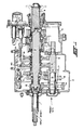
- a twin countershaft compound transmission has an input shaft 1, a main section 2, an auxiliary section 3 and an output shaft 4.
- a front countershaft 5 which has gear teeth 6 formed on it by machining, hobbing, etc. which involves cutting the grooves between the roots of the teeth, and shaping the teeth to involutes or other standard rolling curves. Transmissions of this general type may be seen by reference to above-mentioned U.S. Patents Nos. 4,432,251; 4,735,109; 4,375,172; 3,105,395 and RE 32,591.
- gear 6 is the "first” gear as identified for the purposes of this invention, and has teeth formed by longitudinal cuts into shaft 5 on what is seen in the cross-hatched section thereof. The cuts between the teeth reduce at portion 14 due to the progressive removal of bite of the cutting (hobbing) tool, herein referred to as"run out".
- Gear 7b is the adjacent "second” gear as identified herein and may extend over “run out” length 14 as shown. However, there can be no mating splines under this run out length 14, which is therefore unsupported rotationally.
- first gear 6 will constantly mesh with a first speed ratio mainshaft gear 40 and, also through idlers (not shown), with a reverse mainshaft gear 41.
- the adjacent second gear 7 is not removable, and it would be desirable to be able to slidingly install its end 15 of gear 7 against a truly transverse abutment or stop for extending gear 6 over the run out length 14.
- a stop for end 15 is provided by cutting the tops off teeth of first gear 7 down to the outside diameter of the nonhatched portion 16 of shaft 5, equal to the inside diameter shown of pushed on and welded gear 7. Provision of the abutment 15 requires a separate machining process, i.e. topping the teeth of the first gear; such separate machining processes are always desirably avoided, if possible.
- the gear shaft assembly, countershaft assembly 42, of the present invention is illustrated in Figure 2.
- Splines 17 for second gear 7 are provided not by machining them separately directly from the shaft 5 as was considered at first, but by producing them from extensions of the teeth of "first" gear 6, by topping the teeth, removing most or all of their addenda and possibly portions of their dedenda also (depending on the design and strength of the splines required).
- extensions of all the set of teeth are used, not only to give more strength and distribution of forces to the spline set, but also to avoid the time and expense of machining away whole teeth.
- the splines may be formed as extensions of gear teeth 6 in a reduced diameter portion of the shaft.
- Assembly 42 has no wasted axial run out length in shaft 5, and a proper transverse abutment shoulder 18 can be provided by all the teeth addenda of the first gear. No internally unsplined extension of the adjacent second gear 7 is required to make the abutment possible, therefore gear 7 can be slid rightward fully supported by splines right up to abutment with teeth addenda of first gear 6.
- Circumferential misalignment of splines 17 with teeth of gear 6 is impossible, because the splines are derived from the teeth, and little or no flank or lateral treatment of either is required after production of the splines.
- Axial positioning of the second gears is provided by the shoulder 18 and snap rings 45 or the like.
- keyways e.g. milled Woodruff key seats
- these are machined from the tooth intervals or valleys, and all the spline teeth themselves must be entirely removed by machining.
- Such an amount of machining will usually make the idea of machining keyway slots from the first gear a less attractive proposition than partially machining a set of teeth into respective involute or other splines.
- Even the provision of a keyway can be avoided, by producing an integral key direct from one tooth (removing the others).
- gear 44 is a countershaft gear used to drive a PTO device or the like.
- the splined teeth are in and extend the entire axial length of a second shaft portion 50, adjacent the first shaft portion 51 on which the first gear teeth 6 are formed, and that the second shaft portion, in its finished configuration, have an outer diameter 52 greater than the minor diameter and no larger than, preferably smaller than, the major diameter of the first gear 6 gear teeth.
- a prior art gear tooth 19 has a machine cutter axis 20, an axial end edge 21, a root 22 and a run-out 23.
- a spline, not shown except for a run-out length at its root 24 is in effect spaced a long way from the gear tooth 19 by the two axial lengths 23, 24 of run-out.
- this axial length is wasted as far as giving driving strength to the spline-mounted second gear.
- Figure 3B shows a gear shaft according to the present invention including a tooth 25 which originally extended over a length 26 extended for a spline 27 (or a key 27), and has been topped over length 27 to form the spline or integral key.
- the tooth need not be topped, but topping has the advantage of providing an abutment 28 to be used for locating a "second" gear to be slid over the splines or key 27.
- the second gear (not shown) does not have to be welded on, and separate splines do not have to be made. Therefore, there is no wasted run-out 23 which Figure 1 or Figure 3A illustrate.
- Figure 4 shows run-out 23 of tooth 19 if a keyway 29 is to be provided - again demonstrating wasted axial length.
- Figure 5 shows three typical alternative keys 30A or 30B or 31 to be inserted in keyway slot 29, as it is well-known.
- the inventive key 27 is integral, and so improves safety and economy in that it does not need to be installed separately.
- Figure 6A shows another disadvantage of the prior art structure illustrated in Figure 33A, namely that separate machining of the spline 27 and the tooth 19 leads not only to run-out and unused axial length, but also to an axial non-alignment of circumferential features - due to the two machining processes having to be set up separate.
- the misalignment is illustrated at 32 and is inherent in having had to set up and load a machine, machine the gear teeth 19, unload, transfer to another machine (or possibly reprogram a common machine), load for machining splines 27, and unload. Not only are there many steps, but the aforesaid run-out and misalignment problems arise.
- the orientation of one gear relative to the others i.e. "timing” is a major consideration in a constant mesh multiple countershaft transmission.
- the diameter of that portion of the shaft destined for the set of splines can be reduced by machining to the selected outside diameter of the spline set, and then the teeth and their extensions can be produced.
- the splines are then partly or completely produced at the same time and in the same step, as the tooth extensions.
- improved transmission gear shaft carrying at least one first gear (6) formed integrally therewith and one second gear (7) removably mounted thereto for rotation therewith is provided.
Landscapes
- Engineering & Computer Science (AREA)
- General Engineering & Computer Science (AREA)
- Mechanical Engineering (AREA)
- Gears, Cams (AREA)
- Structure Of Transmissions (AREA)
- Gear Transmission (AREA)
- Retarders (AREA)
Applications Claiming Priority (2)
| Application Number | Priority Date | Filing Date | Title |
|---|---|---|---|
| GB9016768 | 1990-07-31 | ||
| GB909016768A GB9016768D0 (en) | 1990-07-31 | 1990-07-31 | Transmission shaft carrying at least two gears |
Publications (2)
| Publication Number | Publication Date |
|---|---|
| EP0469715A1 true EP0469715A1 (de) | 1992-02-05 |
| EP0469715B1 EP0469715B1 (de) | 1994-08-03 |
Family
ID=10679927
Family Applications (1)
| Application Number | Title | Priority Date | Filing Date |
|---|---|---|---|
| EP91305833A Expired - Lifetime EP0469715B1 (de) | 1990-07-31 | 1991-06-27 | Wechselgetriebe mit mindestens zwei Zahnräder aufweisender Vorgelegewelle |
Country Status (9)
| Country | Link |
|---|---|
| US (1) | US5272929A (de) |
| EP (1) | EP0469715B1 (de) |
| JP (1) | JP3134126B2 (de) |
| KR (1) | KR960015238B1 (de) |
| CA (1) | CA2048123C (de) |
| DE (1) | DE69103237T2 (de) |
| ES (1) | ES2057775T3 (de) |
| GB (1) | GB9016768D0 (de) |
| TR (1) | TR26849A (de) |
Cited By (1)
| Publication number | Priority date | Publication date | Assignee | Title |
|---|---|---|---|---|
| EP0641957A1 (de) * | 1993-09-08 | 1995-03-08 | Robert Bosch Gmbh | Stirnradgetriebe, insbesondere für Stellantriebe von Sitzen in Kraftfahrzeugen |
Families Citing this family (12)
| Publication number | Priority date | Publication date | Assignee | Title |
|---|---|---|---|---|
| US5465630A (en) * | 1993-09-14 | 1995-11-14 | Kubota Corporation | Drive transmitting apparatus for a working vehicle |
| US5970810A (en) | 1998-04-01 | 1999-10-26 | Eaton Corporation | Adaptive splitter actuator engagement force control |
| US5950491A (en) | 1998-04-01 | 1999-09-14 | Eaton Corporation | Adaptive neutral sensing |
| US5989155A (en) | 1998-04-01 | 1999-11-23 | Eaton Corporation | Engine fuel control for completing shifts in controller-assisted, manually shifted transmission |
| US5984831A (en) | 1998-04-01 | 1999-11-16 | Eaton Corporation | Adaptive upshift jaw clutch engagement control |
| US5911787A (en) | 1998-04-01 | 1999-06-15 | Eaton Corporation | Dynamic range shift actuation |
| US6042504A (en) | 1998-04-01 | 2000-03-28 | Eaton Corporation | Range shift control |
| US5974906A (en) | 1998-04-01 | 1999-11-02 | Eaton Corporation | Jaw clutch engagement control for assisted, manually shifted, splitter-type transmission system |
| US6199865B1 (en) * | 1998-09-30 | 2001-03-13 | Igor Goldman | Logical game element |
| US7905812B2 (en) * | 2007-02-02 | 2011-03-15 | Eaton Corporation | PTO brake |
| US8046140B2 (en) | 2008-01-18 | 2011-10-25 | Eaton Corporation | PTO overspeed protection strategy |
| US20160061249A1 (en) * | 2014-08-29 | 2016-03-03 | Douglas H. Powell | Adjustable shear key |
Citations (4)
| Publication number | Priority date | Publication date | Assignee | Title |
|---|---|---|---|---|
| FR404987A (fr) * | 1908-07-10 | 1909-12-16 | Oscar Charles Selbach | Perfectionnements aux mécanismes de changement de vitesse |
| DE1180598B (de) * | 1957-10-24 | 1964-10-29 | Veeder Root Inc | Stufenzahnrad fuer Wechselgetriebe |
| DE2937143A1 (de) * | 1978-11-28 | 1980-05-29 | Fiat Trattori Spa | Schaltgetriebe fuer landwirtschaftliche zugmaschinen u.ae. fahrzeuge |
| EP0043443A2 (de) * | 1980-07-03 | 1982-01-13 | Eaton Corporation | Getriebe mit einer Hauptwelle und mehreren Vorgelegewellen |
Family Cites Families (8)
| Publication number | Priority date | Publication date | Assignee | Title |
|---|---|---|---|---|
| US32591A (en) | 1861-06-18 | Geeenleaf l | ||
| US2704882A (en) * | 1949-12-19 | 1955-03-29 | Kenneth T Snow | Method of making toothed devices |
| US3105395A (en) | 1962-12-26 | 1963-10-01 | Eaton Mfg Co | Automotive device |
| US4154126A (en) * | 1976-10-29 | 1979-05-15 | Borg-Warner Corporation | Compact gear assembly |
| US4375172A (en) | 1978-10-02 | 1983-03-01 | Eaton Corporation | Blocked change gear transmission utilizing resilient shifting mechanisms and improved jaw clutch assembly therefor |
| US4432251A (en) * | 1981-01-29 | 1984-02-21 | Clark Equipment Company | Lost motion transmission control cams |
| US4735109A (en) * | 1981-07-27 | 1988-04-05 | Eaton Corporation | Semi-blocked transmission |
| JPH0730815B2 (ja) * | 1985-02-18 | 1995-04-10 | スズキ株式会社 | 副変速機 |
-
1990
- 1990-07-31 GB GB909016768A patent/GB9016768D0/en active Pending
-
1991
- 1991-06-27 EP EP91305833A patent/EP0469715B1/de not_active Expired - Lifetime
- 1991-06-27 ES ES91305833T patent/ES2057775T3/es not_active Expired - Lifetime
- 1991-06-27 DE DE69103237T patent/DE69103237T2/de not_active Expired - Fee Related
- 1991-07-22 US US07/733,799 patent/US5272929A/en not_active Expired - Fee Related
- 1991-07-26 KR KR1019910012879A patent/KR960015238B1/ko not_active Expired - Fee Related
- 1991-07-26 JP JP03210228A patent/JP3134126B2/ja not_active Expired - Fee Related
- 1991-07-26 TR TR00747/91A patent/TR26849A/xx unknown
- 1991-07-30 CA CA002048123A patent/CA2048123C/en not_active Expired - Fee Related
Patent Citations (4)
| Publication number | Priority date | Publication date | Assignee | Title |
|---|---|---|---|---|
| FR404987A (fr) * | 1908-07-10 | 1909-12-16 | Oscar Charles Selbach | Perfectionnements aux mécanismes de changement de vitesse |
| DE1180598B (de) * | 1957-10-24 | 1964-10-29 | Veeder Root Inc | Stufenzahnrad fuer Wechselgetriebe |
| DE2937143A1 (de) * | 1978-11-28 | 1980-05-29 | Fiat Trattori Spa | Schaltgetriebe fuer landwirtschaftliche zugmaschinen u.ae. fahrzeuge |
| EP0043443A2 (de) * | 1980-07-03 | 1982-01-13 | Eaton Corporation | Getriebe mit einer Hauptwelle und mehreren Vorgelegewellen |
Cited By (1)
| Publication number | Priority date | Publication date | Assignee | Title |
|---|---|---|---|---|
| EP0641957A1 (de) * | 1993-09-08 | 1995-03-08 | Robert Bosch Gmbh | Stirnradgetriebe, insbesondere für Stellantriebe von Sitzen in Kraftfahrzeugen |
Also Published As
| Publication number | Publication date |
|---|---|
| CA2048123C (en) | 1996-09-03 |
| JPH04248045A (ja) | 1992-09-03 |
| DE69103237T2 (de) | 1995-04-06 |
| DE69103237D1 (de) | 1994-09-08 |
| EP0469715B1 (de) | 1994-08-03 |
| JP3134126B2 (ja) | 2001-02-13 |
| ES2057775T3 (es) | 1994-10-16 |
| CA2048123A1 (en) | 1992-02-01 |
| GB9016768D0 (en) | 1990-09-12 |
| TR26849A (tr) | 1994-08-19 |
| KR960015238B1 (ko) | 1996-11-04 |
| US5272929A (en) | 1993-12-28 |
| KR920002958A (ko) | 1992-02-28 |
Similar Documents
| Publication | Publication Date | Title |
|---|---|---|
| US5272929A (en) | Transmission shaft carrying at least two gears | |
| EP1511943B1 (de) | Baureihe von wellen und verfahren zur fertigung | |
| DE3635916C1 (de) | Verzahnung fuer eine Wellen-Nabenverbindung | |
| CA1153908A (en) | Multiple countershaft simple transmission | |
| EP1389694B1 (de) | Schiebemuffe für eine Kraftübertragungseinrichtung sowie Vorrichtung zur Pressformung dafür | |
| US5791205A (en) | Anti-rotation spline teeth for differential case | |
| EP1532383B1 (de) | Getriebe mit direktem gang | |
| US2079513A (en) | Process for producing clutch teeth | |
| US4709590A (en) | Herringbone geared multiple load sharing countershaft transmission | |
| US2457942A (en) | Gear construction and arrangement | |
| DE10124401B4 (de) | Manuelles Getriebe | |
| US4270639A (en) | Synchronizing arrangement for a motor vehicle gear box | |
| US6857827B2 (en) | Spindle for machining accurate inner grooves | |
| CH318564A (de) | Getriebe mit verschiebbaren Schraubenrad | |
| US3137376A (en) | Means for coupling transmission gears | |
| US10753451B2 (en) | Hollow gear with inner toothing and crown toothing, as well as method for the production thereof and transmission having a hollow gear of this type | |
| US4599775A (en) | Method for manufacturing synchronizer clutch teeth | |
| US5069575A (en) | Roll forming notches in a thin-wall power transmission member | |
| US5379622A (en) | Method of forming helical splines with stoppers on a rotary shaft, and rolling tools for practicing the method | |
| DE3022958A1 (de) | Keilwellenkupplung | |
| US3341918A (en) | Burr removing broach and method of broaching | |
| JP3078728B2 (ja) | 変速機のドッグクラッチ付ギヤ | |
| JPH049238A (ja) | アウトサイドリングの製造方法 | |
| US5580327A (en) | Hollow wheel for a sun-and-planet toothed wheel gearing | |
| US4882926A (en) | Roll forming notches in a thin-wall power transmission member |
Legal Events
| Date | Code | Title | Description |
|---|---|---|---|
| PUAI | Public reference made under article 153(3) epc to a published international application that has entered the european phase |
Free format text: ORIGINAL CODE: 0009012 |
|
| AK | Designated contracting states |
Kind code of ref document: A1 Designated state(s): DE ES FR GB IT SE |
|
| 17P | Request for examination filed |
Effective date: 19920214 |
|
| 17Q | First examination report despatched |
Effective date: 19930430 |
|
| GRAA | (expected) grant |
Free format text: ORIGINAL CODE: 0009210 |
|
| ITF | It: translation for a ep patent filed | ||
| AK | Designated contracting states |
Kind code of ref document: B1 Designated state(s): DE ES FR GB IT SE |
|
| REF | Corresponds to: |
Ref document number: 69103237 Country of ref document: DE Date of ref document: 19940908 |
|
| REG | Reference to a national code |
Ref country code: ES Ref legal event code: FG2A Ref document number: 2057775 Country of ref document: ES Kind code of ref document: T3 |
|
| ET | Fr: translation filed | ||
| EAL | Se: european patent in force in sweden |
Ref document number: 91305833.5 |
|
| PLBE | No opposition filed within time limit |
Free format text: ORIGINAL CODE: 0009261 |
|
| STAA | Information on the status of an ep patent application or granted ep patent |
Free format text: STATUS: NO OPPOSITION FILED WITHIN TIME LIMIT |
|
| 26N | No opposition filed | ||
| REG | Reference to a national code |
Ref country code: GB Ref legal event code: IF02 |
|
| PGFP | Annual fee paid to national office [announced via postgrant information from national office to epo] |
Ref country code: GB Payment date: 20040505 Year of fee payment: 14 |
|
| PGFP | Annual fee paid to national office [announced via postgrant information from national office to epo] |
Ref country code: FR Payment date: 20040602 Year of fee payment: 14 |
|
| PGFP | Annual fee paid to national office [announced via postgrant information from national office to epo] |
Ref country code: SE Payment date: 20040603 Year of fee payment: 14 |
|
| PGFP | Annual fee paid to national office [announced via postgrant information from national office to epo] |
Ref country code: ES Payment date: 20040617 Year of fee payment: 14 |
|
| PGFP | Annual fee paid to national office [announced via postgrant information from national office to epo] |
Ref country code: DE Payment date: 20040630 Year of fee payment: 14 |
|
| PG25 | Lapsed in a contracting state [announced via postgrant information from national office to epo] |
Ref country code: IT Free format text: LAPSE BECAUSE OF NON-PAYMENT OF DUE FEES;WARNING: LAPSES OF ITALIAN PATENTS WITH EFFECTIVE DATE BEFORE 2007 MAY HAVE OCCURRED AT ANY TIME BEFORE 2007. THE CORRECT EFFECTIVE DATE MAY BE DIFFERENT FROM THE ONE RECORDED. Effective date: 20050627 Ref country code: GB Free format text: LAPSE BECAUSE OF NON-PAYMENT OF DUE FEES Effective date: 20050627 |
|
| PG25 | Lapsed in a contracting state [announced via postgrant information from national office to epo] |
Ref country code: SE Free format text: LAPSE BECAUSE OF NON-PAYMENT OF DUE FEES Effective date: 20050628 Ref country code: ES Free format text: LAPSE BECAUSE OF NON-PAYMENT OF DUE FEES Effective date: 20050628 |
|
| PG25 | Lapsed in a contracting state [announced via postgrant information from national office to epo] |
Ref country code: DE Free format text: LAPSE BECAUSE OF NON-PAYMENT OF DUE FEES Effective date: 20060103 |
|
| EUG | Se: european patent has lapsed | ||
| PG25 | Lapsed in a contracting state [announced via postgrant information from national office to epo] |
Ref country code: FR Free format text: LAPSE BECAUSE OF NON-PAYMENT OF DUE FEES Effective date: 20060228 |
|
| GBPC | Gb: european patent ceased through non-payment of renewal fee |
Effective date: 20050627 |
|
| REG | Reference to a national code |
Ref country code: FR Ref legal event code: ST Effective date: 20060228 |
|
| REG | Reference to a national code |
Ref country code: ES Ref legal event code: FD2A Effective date: 20050628 |