EP0469734A1 - Luftkissenvorrichtung mit verstärkter Aufblasbefestigung - Google Patents
Luftkissenvorrichtung mit verstärkter Aufblasbefestigung Download PDFInfo
- Publication number
- EP0469734A1 EP0469734A1 EP91306274A EP91306274A EP0469734A1 EP 0469734 A1 EP0469734 A1 EP 0469734A1 EP 91306274 A EP91306274 A EP 91306274A EP 91306274 A EP91306274 A EP 91306274A EP 0469734 A1 EP0469734 A1 EP 0469734A1
- Authority
- EP
- European Patent Office
- Prior art keywords
- air bag
- restraint system
- retainer ring
- occupant restraint
- inflation gas
- Prior art date
- Legal status (The legal status is an assumption and is not a legal conclusion. Google has not performed a legal analysis and makes no representation as to the accuracy of the status listed.)
- Granted
Links
- 239000000463 material Substances 0.000 claims abstract description 21
- 239000004744 fabric Substances 0.000 claims description 16
- 239000004033 plastic Substances 0.000 claims description 6
- 229920003023 plastic Polymers 0.000 claims description 6
- 210000005069 ears Anatomy 0.000 claims description 3
- 239000007789 gas Substances 0.000 abstract description 18
- 238000013461 design Methods 0.000 description 8
- 239000004677 Nylon Substances 0.000 description 3
- 239000011324 bead Substances 0.000 description 3
- 230000004048 modification Effects 0.000 description 3
- 238000012986 modification Methods 0.000 description 3
- 229920001778 nylon Polymers 0.000 description 3
- 230000035699 permeability Effects 0.000 description 3
- 230000008901 benefit Effects 0.000 description 2
- 238000010276 construction Methods 0.000 description 2
- 238000011161 development Methods 0.000 description 2
- 238000004519 manufacturing process Methods 0.000 description 2
- 238000012360 testing method Methods 0.000 description 2
- 239000004957 Zytel Substances 0.000 description 1
- 229920006102 Zytel® Polymers 0.000 description 1
- 230000008859 change Effects 0.000 description 1
- 239000011248 coating agent Substances 0.000 description 1
- 238000000576 coating method Methods 0.000 description 1
- 239000003779 heat-resistant material Substances 0.000 description 1
- 238000001746 injection moulding Methods 0.000 description 1
- 238000009434 installation Methods 0.000 description 1
- 229920001084 poly(chloroprene) Polymers 0.000 description 1
- 230000009467 reduction Effects 0.000 description 1
- 230000002787 reinforcement Effects 0.000 description 1
- 230000003014 reinforcing effect Effects 0.000 description 1
- 238000005728 strengthening Methods 0.000 description 1
- 238000012546 transfer Methods 0.000 description 1
- 238000009423 ventilation Methods 0.000 description 1
Images

Classifications
-
- B—PERFORMING OPERATIONS; TRANSPORTING
- B60—VEHICLES IN GENERAL
- B60R—VEHICLES, VEHICLE FITTINGS, OR VEHICLE PARTS, NOT OTHERWISE PROVIDED FOR
- B60R21/00—Arrangements or fittings on vehicles for protecting or preventing injuries to occupants or pedestrians in case of accidents or other traffic risks
- B60R21/02—Occupant safety arrangements or fittings, e.g. crash pads
- B60R21/16—Inflatable occupant restraints or confinements designed to inflate upon impact or impending impact, e.g. air bags
- B60R21/20—Arrangements for storing inflatable members in their non-use or deflated condition; Arrangement or mounting of air bag modules or components
- B60R21/217—Inflation fluid source retainers, e.g. reaction canisters; Connection of bags, covers, diffusers or inflation fluid sources therewith or together
-
- B—PERFORMING OPERATIONS; TRANSPORTING
- B60—VEHICLES IN GENERAL
- B60R—VEHICLES, VEHICLE FITTINGS, OR VEHICLE PARTS, NOT OTHERWISE PROVIDED FOR
- B60R21/00—Arrangements or fittings on vehicles for protecting or preventing injuries to occupants or pedestrians in case of accidents or other traffic risks
-
- B—PERFORMING OPERATIONS; TRANSPORTING
- B60—VEHICLES IN GENERAL
- B60R—VEHICLES, VEHICLE FITTINGS, OR VEHICLE PARTS, NOT OTHERWISE PROVIDED FOR
- B60R21/00—Arrangements or fittings on vehicles for protecting or preventing injuries to occupants or pedestrians in case of accidents or other traffic risks
- B60R21/02—Occupant safety arrangements or fittings, e.g. crash pads
- B60R21/16—Inflatable occupant restraints or confinements designed to inflate upon impact or impending impact, e.g. air bags
- B60R21/23—Inflatable members
- B60R21/231—Inflatable members characterised by their shape, construction or spatial configuration
-
- B—PERFORMING OPERATIONS; TRANSPORTING
- B60—VEHICLES IN GENERAL
- B60R—VEHICLES, VEHICLE FITTINGS, OR VEHICLE PARTS, NOT OTHERWISE PROVIDED FOR
- B60R21/00—Arrangements or fittings on vehicles for protecting or preventing injuries to occupants or pedestrians in case of accidents or other traffic risks
- B60R21/02—Occupant safety arrangements or fittings, e.g. crash pads
- B60R21/16—Inflatable occupant restraints or confinements designed to inflate upon impact or impending impact, e.g. air bags
- B60R21/23—Inflatable members
- B60R21/235—Inflatable members characterised by their material
- B60R2021/23533—Inflatable members characterised by their material characterised by the manufacturing process
- B60R2021/23538—Sewing
Definitions
- This invention is elated to an air cushion restraint system (ACRS) for providing vehicle occupant protection in the event of a vehicle impact, and particularly, to an air bag construction for providing enhanced strength in the area of the attachment of the air bag to the vehicle support structure.
- ACRS air cushion restraint system
- Impact actuated inflatable occupant restraint systems typically comprise a source of a non- combustible inflating gas and a folded inflatable air bag.
- a crash sensor is used to detect deceleration of the vehicle due to impact and actuates the inflator.
- the bag is deployed to provide a resilient restraint for absorbing the kinetic energy of the occupant's body within the vehicle.
- the inflator unit is mounted to a vehicle support structure, and the air bag, which defines an enclosed volume for receiving the inflation gas, is also attached to the support structure.
- the inflation gas typically fills the air bag through an inflation gas opening or mouth.
- the air bag is attached to the support structure around the inflation opening, usually by being clamped between the ACRS housing and a mounting ring.
- Air cushion restraint systems designed for the driver's side of a motor vehicle are generally packed into the steering wheel whereas the passenger side ACRS is mounted inside the vehicle instrument panel.
- FMVSS Federal Motor Vehicle Safety Standards
- the air bag features a retainer ring, preferably made of a polymeric plastic material which is sewn to the air bag fabric circumscribing the inflation or mounting opening and includes means for engaging with the restraint support structure.
- Another aspect of the present invention is an air bag design featuring enhancements in the manner of assembly which reduce the number of discrete fasteners required around a perimeter air bag mounting frame which must be fastened, while still providing a secure connection between the air bag and the support structure.
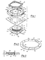
- ACRS 10 generally comprises inflator assembly 12, support plate 14, air bag 16, and mounting ring 18.
- Inflator assembly 12 contains a gas generating material which produces inflation gas when it is actuated by an electrical signal on signal line 22.
- Inflator assembly 12 includes a mounting flange 24 which surrounds the generally disk-shaped inflator assembly and has four fastener holes 26 to allow threaded fasteners to pass through the mounting flange. Additional fastener holes 28 are spaced around mounting flange 24, with two of such additional fastener holes shown between each of fastener holes 26.
- Inflation nozzle 30 is shown positioned above mounting flange 24, with respect to the orientation of the elements shown in Figure 1, and is the escape route for inflation gases when the inflator is actuated. The bottom side of inflator assembly 12 (not shown) is sealed so that the inflation gases generated by the unit escape through inflation nozzle 30.
- Support plate 14 is designed to be securely affixed to a vehicle support structure (not shown).
- ACRS 10 shown in Figure 1 is designed to be mounted to a steering column assembly of a motor vehicle to provide protection for the vehicle driver.
- Support plate 14 defines a central inflator opening 34. Spaced around inflator opening 34 are fastener holes 36 and an additional series of fastener holes 38, both of which are oriented to be in registry with corresponding inflator assembly fastener holes 26 and 28, respectively.
- Support plate 14 would have additional fastener features (not shown) to enable it to be mounted to the vehicle structure in a secure manner.
- Mounting ring 18, also shown in Figure 1 defines an inflator opening 42 and has four threaded fastener bolts 44 projecting from it in an axial direction relative to the plane of the ring.
- Bolts 44 are welded to or otherwise affixed to mounting ring 18.
- Bolts 44 are oriented to pass through the mounting plate and inflator fastener holes 36 and 26 when the ACRS unit is assembled.
- rivets or other fasteners could take the place of threaded bolts 44.
- Air bag 16 becomes clamped between support plate 14 and mounting ring 18 during assembly. Air bag 16 also defines an inflator or mounting opening 48 which, in accordance with the present invention, is reinforced through the use of a retainer ring 50, best shown in Figure 2.
- Air bag 16 can be made from a variety of materials such as woven nylon fabric. In some applications, such as the typical driver side air bag, the air bag material is substantially gas impermeable. Resistance to gas permeability is often provided by an inside coating of a heat resistant material such as neoprene to protect the nylon fabric from the heat associated with gas generation. Depending upon the application, various degrees of permeability of the air bag material to the inflation gases are selected. Often it is desirable to provide a controlled deflation of an air bag after deployment.
- Air bag 16 may also include additional features (not shown) such as tethers, which are internal fabric ribbons or sheets which are used to control the inflated shape of the bag.
- Retainer ring 50 is preferably made from a polymeric plastic material such as Dupont Zytel ST801 nylon and features an inside opening diameter which generally corresponds with air bag inflator opening 48.
- Retainer ring 50 is semi-rigid and non-porous and is preferably formed as an unitary product by an injection molding.
- Four fastener holes 52 are provided around the perimeter of the retainer ring 50 in registry with the position of support plate bolts 44. Between fastener holes 52, retainer ring 50 features a pair of projecting posts 54 integrally formed with the retainer ring. Posts 54 project in an axial direction relative to the plane of the retainer ring and are oriented to pass through inflator holes 28 and support plate holes 38.
- the perimeter of air bag inflation opening 48 includes a pair of fabric rings 56 overlying the retainer ring on the inside of the bag, and another fabric ring 57 on the outside of the bag. Rings 56 and 57 may be made of the same woven material which comprises air bag body portion 58. Fabric rings 56 and 57, and retainer ring 50 are sewn to air bag body portion 58, as shown in Figure 3, along stitching lines 59. Fabric ring 57 and body portion 58 also includes apertures 60 for the passage of the posts 54. The fabric layers comprising air bag 16 also include apertures 61 for the passage of bolts 44.
- retainer ring 50 for air bag 16 significantly reduces the complexity of air bag assembly since it is only necessary to fit posts 54 within the corresponding apertures and, therefore, securing individual fasteners in the location of posts 54 is unnecessary.
- the posts 54 loosely fit within the corresponding holes so as to facilitate assembly.
- tinnerman nuts or similar fasteners could be used for one or more of posts 54.
- Retainer ring 50 includes a bead 64 along its outer periphery. Bead 64 presents a smooth edge which prevents cutting or abrading of the air bag fabric in that area. In some air cushion designs and especially those featuring internal tethers which control the inflated shape of the bag or in cases where vent holes are provided which must be oriented in a particular position, it is desirable to provide a predetermined indexing or rotational orientation of the air bag with respect to support plate 14.
- indexing post 68 is provided which projects from mounting ring 18 and passes through corresponding holes 70 through the air bag 16, support plate 14, and inflator assembly 12. Since only a single indexing post is provided, the components can only be assembled in one particular indexed position.
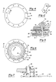
- FIGS 4 and 5 illustrate a retainer ring 74 in accordance with the second embodiment of this invention.
- Retainer ring 74 differs from retainer ring 50 in that the projecting posts 76 have a lateral slot 78 and projecting tabs or ears 80 which allow the posts to enter the corresponding apertures and snap-fit into position during assembly to hold the parts together.
- Retainer ring 74 also differs in that posts 76 have axial holes 82 through them so that a rivet 84 can be installed through the posts, thereby eliminating the use of threaded fasteners in separate holes as shown in conjunction with the first embodiment. In one design of this embodiment four rivets 84 would be used for securing the components of an ACRS together in accordance with this invention.
- Figure 5 shows retainer ring 74 shown with the elements of Figure 1 and further showing the installation of rivet 84 through post 76.
- an ACRS incorporating retainer ring 74 would be similar in design and operation to that shown in Figures 1, 2 and 3.
- a modification of retainer ring 74 shown in Figure 11 and designated by reference number 79 would feature holes 81 in the place of each of posts 76, and conventional fastener would be installed through them for securing the components together.
- Such a design would provide a strengthening of the air bag opening without the assembly features of the other embodiments.
- Figures 6 and 7 illustrate a third embodiment of a retainer ring 88 in accordance with the present invention which is substantially identical to retainer ring 74 except that it features tabs 90 associated with each of posts 76 which can be folded outwardly along fold lines 92 and have aperture 94 which allows the tabs to be folded over post 76 as shown in Figure 7.
- Figure 7 shows the position of the tabs in phantom lines as the retainer ring is initially formed as shown in Figure 6, and also shows in full lines the tabs after being folded over and into engagement with post 76.
- the function of tabs 90 is to provide additional protection for the edges of the air bag material around inflation opening 48 from damage due to the hot inflation gases issuing from inflator nozzle 30.
- Elements of retainer ring 88 equivalent to those of the prior embodiments are identified by like reference numbers.
- FIGs 8 through 10 illustrate an ACRS unit 98 incorporating features of the present invention which is particularly adapted for use as a passenger side restraint system.
- ACRS 98 is conceptually equivalent to the prior embodiments except that the inflation or mounting opening 101 of air bag 102 is rectangular as opposed to circular in shape. Consequently, mounting ring 104 has a rectangular configuration as does inflation opening 106 of support structure 108.
- Figure 9 provides a plan view of rectangular retainer ring 110 which is made from a material such as a polymeric plastic like that used with the prior described embodiments. Due to the large perimeter size of inflation opening 106, it is believed necessary to provide clamping engagement between the air bag mounting components or more intervals as compared with the prior embodiments such as the first embodiment in which only four threaded fasteners are provided. For this embodiment, the fasteners alternate between threaded fastener bolts 112 and projecting retainer ring posts 114.
- Air bag 102 is shown having an internal tether 116 to control the shape of the air bag upon inflation.
- the material comprising air bag 102 is wrapped around retainer ring 110 as shown in Figure 8 and is stitched through to secure the retainer ring.
- a total of ten securing bolts 112 are provided around the periphery of mounting ring 104.
- Retainer ring 110 features apertures 118 which corresponds to the position of bolts 112.
- support structure 108 also features apertures 120 aligned with bolts 112. Between adjacent apertures 118, retainer ring 110 features post 114 which project through corresponding apertures 122 of support structure 108.
- FIG. 10 is a cross-sectional view showing that the retainer ring has a dome area 24 on the opposite surface from post 114 which is provided for the purpose of accommodating shrinkage or sink tendency of the plastic material in the area of post 114 due to its increased section thickness in that area.
- the Figure also shows a bead 126 for compressing the air bag material as discussed above.
Landscapes
- Engineering & Computer Science (AREA)
- Mechanical Engineering (AREA)
- Air Bags (AREA)
- Heating, Cooling, Or Curing Plastics Or The Like In General (AREA)
- Helmets And Other Head Coverings (AREA)
Applications Claiming Priority (2)
| Application Number | Priority Date | Filing Date | Title |
|---|---|---|---|
| US07/559,662 US5064218A (en) | 1988-10-14 | 1990-07-30 | Air cushion restraint device having reinforced inflation attachment |
| US559662 | 1990-07-30 |
Publications (2)
| Publication Number | Publication Date |
|---|---|
| EP0469734A1 true EP0469734A1 (de) | 1992-02-05 |
| EP0469734B1 EP0469734B1 (de) | 1994-12-28 |
Family
ID=24234499
Family Applications (1)
| Application Number | Title | Priority Date | Filing Date |
|---|---|---|---|
| EP91306274A Expired - Lifetime EP0469734B1 (de) | 1990-07-30 | 1991-07-11 | Luftkissenvorrichtung mit verstärkter Aufblasbefestigung |
Country Status (9)
| Country | Link |
|---|---|
| US (1) | US5064218A (de) |
| EP (1) | EP0469734B1 (de) |
| JP (1) | JPH05147486A (de) |
| KR (1) | KR920002407A (de) |
| AT (1) | ATE116227T1 (de) |
| CA (1) | CA2046712A1 (de) |
| DE (1) | DE69106262T2 (de) |
| IE (1) | IE912664A1 (de) |
| MX (1) | MX173999B (de) |
Cited By (15)
| Publication number | Priority date | Publication date | Assignee | Title |
|---|---|---|---|---|
| FR2669877A1 (fr) * | 1990-11-30 | 1992-06-05 | Takata Corp | Structure de fixation du coussin pneumatique d'un dispositif a coussin pneumatique. |
| FR2669878A1 (fr) * | 1990-11-30 | 1992-06-05 | Takata Corp | Structure pour le montage d'un coussin pneumatique dans un dispositif a coussin pneumatique. |
| WO1992021534A1 (en) * | 1991-05-31 | 1992-12-10 | Allied Signal Inc. | Air bag assembly |
| DE4234988A1 (de) * | 1991-10-17 | 1993-04-22 | Trw Inc | Luftsack (airbag)-struktur und formverfahren |
| EP0542418A1 (de) * | 1991-10-17 | 1993-05-19 | Morton International, Inc. | Gaskissenschutzvorrichtung |
| GB2262918A (en) * | 1992-01-06 | 1993-07-07 | Takata Corp | Air bags |
| DE4318279A1 (de) * | 1992-06-02 | 1993-12-09 | Trw Vehicle Safety Systems | Airbaganordnung |
| GB2251222B (en) * | 1990-11-30 | 1995-04-19 | Takata Corp | Air bag system for a passenger's seat and an air bag therefor |
| DE19508533A1 (de) * | 1994-03-15 | 1995-10-12 | Tokai Rika Co Ltd | Airbag-Vorrichtung und Verfahren zum Entfernen einer Aufblaseinheit aus der Airbag-Vorrichtung |
| EP0709260A1 (de) * | 1994-10-18 | 1996-05-01 | Morton International, Inc. | System zur Befestigung eines Airbags |
| CN1042016C (zh) * | 1993-04-26 | 1999-02-10 | Trw莱帕有限公司 | 车辆气袋制约系统 |
| WO2000048867A1 (en) * | 1999-02-16 | 2000-08-24 | Breed Automotive Technology, Inc. | Driver side airbag module |
| EP1114758A1 (de) * | 2000-01-05 | 2001-07-11 | Delphi Automotive Systems Sungwoo Co., Ltd. | Rückhalterung mit Luftumlenkblech für eine Luftsackmontagestuktur |
| EP2006168A3 (de) * | 2007-06-22 | 2010-03-10 | TK Holdings, Inc. | Airbaganordnung |
| CN103121431A (zh) * | 2013-03-07 | 2013-05-29 | 锦州锦恒汽车安全系统有限公司 | 汽车安全气囊撑圈结构 |
Families Citing this family (42)
| Publication number | Priority date | Publication date | Assignee | Title |
|---|---|---|---|---|
| US5368327A (en) * | 1989-07-12 | 1994-11-29 | Toyoda Gosei, Co., Ltd. | Air bag device |
| JP3003264B2 (ja) * | 1991-05-20 | 2000-01-24 | タカタ株式会社 | エアバッグ |
| US5378011A (en) * | 1991-05-31 | 1995-01-03 | Alliedsignal Inc. | Air bag assembly |
| US5176400A (en) * | 1991-07-09 | 1993-01-05 | Textron Inc. | Air bag mounting system |
| US5207450A (en) * | 1991-12-12 | 1993-05-04 | Takata, Inc. | Aspirated air cushion restraint system |
| US5259641A (en) * | 1992-02-25 | 1993-11-09 | General Motors Corporation | Air bag attachment device |
| US5234227A (en) * | 1992-03-02 | 1993-08-10 | General Motors Corporation | Mounting for air bag assembly |
| JP3279643B2 (ja) * | 1992-05-27 | 2002-04-30 | オートリブ デベロップメント アクテボラゲット | エアバッグ |
| US5324072A (en) * | 1992-09-23 | 1994-06-28 | Morton International, Inc. | Side impact air bag |
| US5320379A (en) * | 1993-05-05 | 1994-06-14 | Automotive Systems Laboratory, Inc. | Inflator mounting system |
| US5356174A (en) * | 1993-05-06 | 1994-10-18 | Trw Vehicle Safety Systems Inc. | Vehicle airbag assembly |
| US5531474A (en) * | 1994-04-26 | 1996-07-02 | Breed Automotive Technology, Inc. | Inflator assembly |
| US5419584A (en) * | 1994-05-02 | 1995-05-30 | Morton International, Inc. | Air bag retention clip |
| US5421607A (en) * | 1994-06-15 | 1995-06-06 | General Motors Corporation | Air bag attachment mechanism |
| US5518266A (en) * | 1994-10-20 | 1996-05-21 | Trw Inc. | Vehicle safety apparatus including inflatable restraint |
| US5560642A (en) * | 1995-01-06 | 1996-10-01 | Takata, Inc. | Driver air bag module assembly |
| US5501484A (en) * | 1995-03-20 | 1996-03-26 | Morton International, Inc. | Rivetless cushion retaining ring with tabs which lock the ring in place after rotation |
| JP3144262B2 (ja) * | 1995-03-28 | 2001-03-12 | 豊田合成株式会社 | エアバッグ装置 |
| US5683101A (en) * | 1995-06-07 | 1997-11-04 | Larry J. Winget | Automotive seat plastic air bag cover |
| US5687986A (en) * | 1995-12-28 | 1997-11-18 | Precision Fabric Group | Attachment device for an inflatable protective cushion |
| US5678848A (en) * | 1996-01-17 | 1997-10-21 | Morton International, Inc. | Air bag module with combined assembly and mounting hardware |
| US5639112A (en) * | 1996-02-06 | 1997-06-17 | Trw Vehicle Safety Systems Inc. | Air bag module |
| US5683100A (en) * | 1996-07-12 | 1997-11-04 | Morton International, Inc. | Airbag cushion retainer with annular sewing area |
| US5673930A (en) * | 1996-08-21 | 1997-10-07 | Trw Inc. | Vehicle occupant protection apparatus |
| US6206417B1 (en) | 1998-05-08 | 2001-03-27 | Autoliv Asp, Inc. | Air bag inflator exit gas dispersion features |
| US6250665B1 (en) | 1998-12-15 | 2001-06-26 | Trw Vehicle Safety Systems Inc. | Retainer structure for an inflatable vehicle occupant protection device |
| US6302432B1 (en) * | 1999-10-12 | 2001-10-16 | Trw, Inc. | Deflection tab baseplate for an airbag inflator |
| DE10039800B4 (de) * | 2000-08-16 | 2013-03-14 | Volkswagen Ag | Fahrzeugdach, insbesondere für ein Kraftfahrzeug |
| DE10039803B4 (de) * | 2000-08-16 | 2013-07-04 | Volkswagen Ag | Fahrzeugdach, insbesondere für ein Kraftfahrzeug |
| US6877770B2 (en) * | 2000-10-27 | 2005-04-12 | Ks Centaco Wheel Corporation | Method of preparing air bag module and vehicle support for final process positioning |
| US6695343B1 (en) | 2000-11-20 | 2004-02-24 | Trw Vehicle Safety Systems Inc. | Snap-in air bag module |
| EP1393991B1 (de) * | 2002-08-27 | 2006-05-24 | TRW Automotive Safety Systems GmbH | Gassackmodul |
| US20040169360A1 (en) * | 2003-02-28 | 2004-09-02 | Chavez Spencer William | Single panel airbag |
| EP1506896B1 (de) * | 2003-08-12 | 2011-05-11 | Autoliv Development AB | Luftsackmodul |
| DE202004017428U1 (de) * | 2004-11-10 | 2005-01-27 | Trw Airbag Systems Gmbh | Gasgenerator und Gassackmodul |
| US20060157960A1 (en) * | 2004-12-22 | 2006-07-20 | Daicel Chemical Industries, Ltd. | Gas generator for air bag |
| DE202005011878U1 (de) * | 2005-07-21 | 2005-10-13 | Takata-Petri Ag | Airbagmodul für ein Kraftfahrzeug |
| KR100797134B1 (ko) * | 2006-10-27 | 2008-01-23 | 에스앤티대우(주) | 슬림형 조수석 에어백 모듈을 적용한 저 상해치 조수석에어백 시스템 |
| US20090051146A1 (en) * | 2007-08-22 | 2009-02-26 | Tk Holdings Inc. | Snap-in attachment of inflator for airbag |
| EP2156994B1 (de) * | 2008-08-18 | 2012-09-12 | Autoliv Development AB | Luftsackanordnung |
| CN103465864B (zh) * | 2008-09-30 | 2017-03-15 | Trw空气气袋系统股份有限公司 | 气体发生器、其制造方法以及带有气体发生器的模块 |
| DE102011000051A1 (de) * | 2010-01-08 | 2011-07-14 | TK Holdings, Inc., Mich. | Airbagmodul |
Citations (3)
| Publication number | Priority date | Publication date | Assignee | Title |
|---|---|---|---|---|
| FR2170337A5 (de) * | 1971-07-23 | 1973-09-14 | Nissan Motor | |
| US4887842A (en) * | 1987-08-17 | 1989-12-19 | Kabushiki Kaisha Tokai-Rika-Denki-Seisakusho | Gas bag |
| EP0364267A2 (de) * | 1988-10-14 | 1990-04-18 | Irvin Automotive Products, Inc. | Rückhaltesystem für Fahrzeuginsassen |
Family Cites Families (9)
| Publication number | Priority date | Publication date | Assignee | Title |
|---|---|---|---|---|
| US4111457A (en) * | 1975-12-19 | 1978-09-05 | Bayerische Motoren Werke Ag | Inflatable restraining device for motor vehicles |
| US4286954A (en) * | 1979-12-03 | 1981-09-01 | General Motors Corporation | Method of folding an inflatable restraint cushion |
| DE3630685C2 (de) * | 1986-07-22 | 1994-03-10 | Trw Repa Gmbh | Gaskissen-Aufprallschutzvorrichtung für einen Kraftfahrzeuginsassen |
| US4817828A (en) * | 1986-10-03 | 1989-04-04 | Trw Automotive Products Inc. | Inflatable restraint system |
| US4793631A (en) * | 1986-11-12 | 1988-12-27 | Juichiro Takada | Mounting for inflatable safety bag |
| JPH01247241A (ja) * | 1988-03-29 | 1989-10-03 | Takata Kk | エアバッグ装置のベースプレート及びベースプレート取付構造 |
| US4907819A (en) * | 1988-09-16 | 1990-03-13 | Talley Automotive Products, Inc. | Lightweight non-welded gas generator with rolled spun lip |
| US4913461A (en) * | 1988-12-27 | 1990-04-03 | Talley Automotive Products, Inc. | Airbag module and method of making same |
| US4934734A (en) * | 1989-03-27 | 1990-06-19 | Juichiro Takada | Inflatable air bag for protection of a vehicle occupant |
-
1990
- 1990-07-30 US US07/559,662 patent/US5064218A/en not_active Expired - Lifetime
-
1991
- 1991-07-10 CA CA002046712A patent/CA2046712A1/en not_active Abandoned
- 1991-07-11 EP EP91306274A patent/EP0469734B1/de not_active Expired - Lifetime
- 1991-07-11 AT AT91306274T patent/ATE116227T1/de not_active IP Right Cessation
- 1991-07-11 DE DE69106262T patent/DE69106262T2/de not_active Expired - Fee Related
- 1991-07-29 IE IE266491A patent/IE912664A1/en unknown
- 1991-07-29 MX MX9100411A patent/MX173999B/es not_active IP Right Cessation
- 1991-07-29 KR KR1019910013030A patent/KR920002407A/ko not_active Withdrawn
- 1991-07-29 JP JP3188842A patent/JPH05147486A/ja active Pending
Patent Citations (3)
| Publication number | Priority date | Publication date | Assignee | Title |
|---|---|---|---|---|
| FR2170337A5 (de) * | 1971-07-23 | 1973-09-14 | Nissan Motor | |
| US4887842A (en) * | 1987-08-17 | 1989-12-19 | Kabushiki Kaisha Tokai-Rika-Denki-Seisakusho | Gas bag |
| EP0364267A2 (de) * | 1988-10-14 | 1990-04-18 | Irvin Automotive Products, Inc. | Rückhaltesystem für Fahrzeuginsassen |
Non-Patent Citations (1)
| Title |
|---|
| PATENT ABSTRACTS OF JAPAN vol. 14, no. 367 (M-1008)(4310) 9 August 1990 & JP-A-2 133 266 ( NIPPON PLAST CO LTD ) 22 May 1990 * |
Cited By (27)
| Publication number | Priority date | Publication date | Assignee | Title |
|---|---|---|---|---|
| GB2251222B (en) * | 1990-11-30 | 1995-04-19 | Takata Corp | Air bag system for a passenger's seat and an air bag therefor |
| FR2669878A1 (fr) * | 1990-11-30 | 1992-06-05 | Takata Corp | Structure pour le montage d'un coussin pneumatique dans un dispositif a coussin pneumatique. |
| US5195774A (en) * | 1990-11-30 | 1993-03-23 | Takata Corporation | Air bag attaching structure |
| FR2669877A1 (fr) * | 1990-11-30 | 1992-06-05 | Takata Corp | Structure de fixation du coussin pneumatique d'un dispositif a coussin pneumatique. |
| GB2253378B (en) * | 1990-11-30 | 1995-07-26 | Takata Corp | Structure of an air bag in an air bag system |
| US5308107A (en) * | 1990-11-30 | 1994-05-03 | Takata Corporation | Structure for mounting an air bag in an air bag system |
| GB2250483B (en) * | 1990-11-30 | 1995-07-12 | Takata Corp | Air bag device |
| WO1992021534A1 (en) * | 1991-05-31 | 1992-12-10 | Allied Signal Inc. | Air bag assembly |
| DE4234988A1 (de) * | 1991-10-17 | 1993-04-22 | Trw Inc | Luftsack (airbag)-struktur und formverfahren |
| EP0542418A1 (de) * | 1991-10-17 | 1993-05-19 | Morton International, Inc. | Gaskissenschutzvorrichtung |
| GB2262918A (en) * | 1992-01-06 | 1993-07-07 | Takata Corp | Air bags |
| US5308110A (en) * | 1992-01-06 | 1994-05-03 | Takata Corporation | Structure for mounting an air bag to a container in an air bag device for use in a passenger seat |
| GB2262918B (en) * | 1992-01-06 | 1995-06-14 | Takata Corp | Structure for mounting an air bag to a container in an air bag device |
| DE4318279A1 (de) * | 1992-06-02 | 1993-12-09 | Trw Vehicle Safety Systems | Airbaganordnung |
| DE4318279C2 (de) * | 1992-06-02 | 2000-08-03 | Trw Vehicle Safety Systems | Airbaganordnung |
| CN1042016C (zh) * | 1993-04-26 | 1999-02-10 | Trw莱帕有限公司 | 车辆气袋制约系统 |
| DE19508533C2 (de) * | 1994-03-15 | 1999-03-11 | Tokai Rika Co Ltd | Airbagmodul für Kraftfahrzeuge |
| DE19508533A1 (de) * | 1994-03-15 | 1995-10-12 | Tokai Rika Co Ltd | Airbag-Vorrichtung und Verfahren zum Entfernen einer Aufblaseinheit aus der Airbag-Vorrichtung |
| EP0709260A1 (de) * | 1994-10-18 | 1996-05-01 | Morton International, Inc. | System zur Befestigung eines Airbags |
| US5542692A (en) * | 1994-10-18 | 1996-08-06 | Morton International, Inc. | Inflatable cushion assembly and system |
| WO2000048867A1 (en) * | 1999-02-16 | 2000-08-24 | Breed Automotive Technology, Inc. | Driver side airbag module |
| US6149184A (en) * | 1999-02-16 | 2000-11-21 | Breed Automotive Technology, Inc. | Simplified driver side air bag assembly |
| EP1114758A1 (de) * | 2000-01-05 | 2001-07-11 | Delphi Automotive Systems Sungwoo Co., Ltd. | Rückhalterung mit Luftumlenkblech für eine Luftsackmontagestuktur |
| EP2006168A3 (de) * | 2007-06-22 | 2010-03-10 | TK Holdings, Inc. | Airbaganordnung |
| US8052167B2 (en) | 2007-06-22 | 2011-11-08 | Tk Holdings Inc. | Airbag assembly |
| CN103121431A (zh) * | 2013-03-07 | 2013-05-29 | 锦州锦恒汽车安全系统有限公司 | 汽车安全气囊撑圈结构 |
| CN103121431B (zh) * | 2013-03-07 | 2016-09-14 | 锦州锦恒汽车安全系统有限公司 | 汽车安全气囊撑圈结构 |
Also Published As
| Publication number | Publication date |
|---|---|
| MX9100411A (es) | 1993-01-01 |
| ATE116227T1 (de) | 1995-01-15 |
| IE912664A1 (en) | 1992-02-12 |
| DE69106262T2 (de) | 1995-06-08 |
| MX173999B (es) | 1994-04-13 |
| EP0469734B1 (de) | 1994-12-28 |
| CA2046712A1 (en) | 1992-01-31 |
| JPH05147486A (ja) | 1993-06-15 |
| US5064218A (en) | 1991-11-12 |
| DE69106262D1 (de) | 1995-02-09 |
| KR920002407A (ko) | 1992-02-28 |
Similar Documents
| Publication | Publication Date | Title |
|---|---|---|
| US5064218A (en) | Air cushion restraint device having reinforced inflation attachment | |
| US5997037A (en) | Air bag with tether | |
| EP0838377B1 (de) | Airbag-Bewegungsbegrenzungsband | |
| US5447329A (en) | Air-bag device including protective sheet | |
| US5398958A (en) | Tethered attachment for an air bag | |
| US5772239A (en) | Airbag sub-module having fabric envelope with horn switch | |
| JP2523406B2 (ja) | エアバッグ組立体 | |
| US6209911B1 (en) | Driver side air bag | |
| US7618060B2 (en) | Air bag module with an integral shield | |
| US6612609B1 (en) | Inflatable air bag with inner bag and outer bag | |
| US5609356A (en) | Cylindrical air bag module assembly | |
| JPH08230596A (ja) | 同乗者用エアバック拘束装置 | |
| US5246249A (en) | Air bag unit | |
| US5931491A (en) | Airbag module with a reduced number of fasteners | |
| JPH09164895A (ja) | 自動車用エアバッグモジュール | |
| US5520409A (en) | Cover retention in occupant restraint installations | |
| US5642900A (en) | Air bag attachment to module | |
| US5687986A (en) | Attachment device for an inflatable protective cushion | |
| US5588668A (en) | Air bag module | |
| US5779261A (en) | Vehicle air bag retaining arrangement | |
| US6145872A (en) | Airbag cushion attachment | |
| JPH0651457B2 (ja) | エアバッグ装置 | |
| US6164684A (en) | Fastening structure for interconnecting parts of a vehicle occupant protection apparatus | |
| US5826913A (en) | Air bag with retaining ring | |
| US5295706A (en) | Air bag |
Legal Events
| Date | Code | Title | Description |
|---|---|---|---|
| PUAI | Public reference made under article 153(3) epc to a published international application that has entered the european phase |
Free format text: ORIGINAL CODE: 0009012 |
|
| AK | Designated contracting states |
Kind code of ref document: A1 Designated state(s): AT BE CH DE DK ES FR GB GR IT LI LU NL SE |
|
| 17P | Request for examination filed |
Effective date: 19920801 |
|
| 17Q | First examination report despatched |
Effective date: 19931015 |
|
| GRAA | (expected) grant |
Free format text: ORIGINAL CODE: 0009210 |
|
| AK | Designated contracting states |
Kind code of ref document: B1 Designated state(s): AT BE CH DE DK ES FR GB GR IT LI LU NL SE |
|
| PG25 | Lapsed in a contracting state [announced via postgrant information from national office to epo] |
Ref country code: LI Effective date: 19941228 Ref country code: GR Free format text: LAPSE BECAUSE OF FAILURE TO SUBMIT A TRANSLATION OF THE DESCRIPTION OR TO PAY THE FEE WITHIN THE PRESCRIBED TIME-LIMIT Effective date: 19941228 Ref country code: DK Effective date: 19941228 Ref country code: CH Effective date: 19941228 Ref country code: AT Effective date: 19941228 |
|
| REF | Corresponds to: |
Ref document number: 116227 Country of ref document: AT Date of ref document: 19950115 Kind code of ref document: T |
|
| ET | Fr: translation filed | ||
| EAL | Se: european patent in force in sweden |
Ref document number: 91306274.1 |
|
| REF | Corresponds to: |
Ref document number: 69106262 Country of ref document: DE Date of ref document: 19950209 |
|
| REG | Reference to a national code |
Ref country code: ES Ref legal event code: BA2A |
|
| ITF | It: translation for a ep patent filed | ||
| REG | Reference to a national code |
Ref country code: CH Ref legal event code: PL |
|
| PG25 | Lapsed in a contracting state [announced via postgrant information from national office to epo] |
Ref country code: LU Free format text: LAPSE BECAUSE OF NON-PAYMENT OF DUE FEES Effective date: 19950731 |
|
| PLBE | No opposition filed within time limit |
Free format text: ORIGINAL CODE: 0009261 |
|
| STAA | Information on the status of an ep patent application or granted ep patent |
Free format text: STATUS: NO OPPOSITION FILED WITHIN TIME LIMIT |
|
| 26N | No opposition filed | ||
| PGFP | Annual fee paid to national office [announced via postgrant information from national office to epo] |
Ref country code: FR Payment date: 19960617 Year of fee payment: 6 |
|
| PGFP | Annual fee paid to national office [announced via postgrant information from national office to epo] |
Ref country code: SE Payment date: 19960618 Year of fee payment: 6 |
|
| PGFP | Annual fee paid to national office [announced via postgrant information from national office to epo] |
Ref country code: NL Payment date: 19960624 Year of fee payment: 6 |
|
| PGFP | Annual fee paid to national office [announced via postgrant information from national office to epo] |
Ref country code: BE Payment date: 19960625 Year of fee payment: 6 |
|
| PGFP | Annual fee paid to national office [announced via postgrant information from national office to epo] |
Ref country code: GB Payment date: 19960626 Year of fee payment: 6 |
|
| PGFP | Annual fee paid to national office [announced via postgrant information from national office to epo] |
Ref country code: ES Payment date: 19960717 Year of fee payment: 6 |
|
| REG | Reference to a national code |
Ref country code: ES Ref legal event code: FA2A Effective date: 19970217 |
|
| PGFP | Annual fee paid to national office [announced via postgrant information from national office to epo] |
Ref country code: DE Payment date: 19970624 Year of fee payment: 7 |
|
| PG25 | Lapsed in a contracting state [announced via postgrant information from national office to epo] |
Ref country code: GB Free format text: LAPSE BECAUSE OF NON-PAYMENT OF DUE FEES Effective date: 19970711 |
|
| PG25 | Lapsed in a contracting state [announced via postgrant information from national office to epo] |
Ref country code: SE Effective date: 19970712 Ref country code: ES Free format text: LAPSE BECAUSE OF NON-PAYMENT OF DUE FEES Effective date: 19970712 |
|
| PG25 | Lapsed in a contracting state [announced via postgrant information from national office to epo] |
Ref country code: BE Free format text: LAPSE BECAUSE OF NON-PAYMENT OF DUE FEES Effective date: 19970731 |
|
| BERE | Be: lapsed |
Owner name: TAKATA INC. Effective date: 19970731 |
|
| PG25 | Lapsed in a contracting state [announced via postgrant information from national office to epo] |
Ref country code: NL Free format text: LAPSE BECAUSE OF NON-PAYMENT OF DUE FEES Effective date: 19980201 |
|
| GBPC | Gb: european patent ceased through non-payment of renewal fee |
Effective date: 19970711 |
|
| PG25 | Lapsed in a contracting state [announced via postgrant information from national office to epo] |
Ref country code: FR Free format text: LAPSE BECAUSE OF NON-PAYMENT OF DUE FEES Effective date: 19980331 |
|
| NLV4 | Nl: lapsed or anulled due to non-payment of the annual fee |
Effective date: 19980201 |
|
| EUG | Se: european patent has lapsed |
Ref document number: 91306274.1 |
|
| REG | Reference to a national code |
Ref country code: FR Ref legal event code: ST |
|
| PG25 | Lapsed in a contracting state [announced via postgrant information from national office to epo] |
Ref country code: DE Free format text: LAPSE BECAUSE OF NON-PAYMENT OF DUE FEES Effective date: 19990501 |
|
| PG25 | Lapsed in a contracting state [announced via postgrant information from national office to epo] |
Ref country code: IT Free format text: LAPSE BECAUSE OF NON-PAYMENT OF DUE FEES Effective date: 20050711 |