EP0469822A2 - Moteur sans balai - Google Patents
Moteur sans balai Download PDFInfo
- Publication number
- EP0469822A2 EP0469822A2 EP91306916A EP91306916A EP0469822A2 EP 0469822 A2 EP0469822 A2 EP 0469822A2 EP 91306916 A EP91306916 A EP 91306916A EP 91306916 A EP91306916 A EP 91306916A EP 0469822 A2 EP0469822 A2 EP 0469822A2
- Authority
- EP
- European Patent Office
- Prior art keywords
- rotor
- switching element
- magnetic sensor
- coil
- power source
- Prior art date
- Legal status (The legal status is an assumption and is not a legal conclusion. Google has not performed a legal analysis and makes no representation as to the accuracy of the status listed.)
- Granted
Links
Images


Classifications
-
- H—ELECTRICITY
- H02—GENERATION; CONVERSION OR DISTRIBUTION OF ELECTRIC POWER
- H02P—CONTROL OR REGULATION OF ELECTRIC MOTORS, ELECTRIC GENERATORS OR DYNAMO-ELECTRIC CONVERTERS; CONTROLLING TRANSFORMERS, REACTORS OR CHOKE COILS
- H02P6/00—Arrangements for controlling synchronous motors or other dynamo-electric motors using electronic commutation dependent on the rotor position; Electronic commutators therefor
- H02P6/20—Arrangements for starting
-
- H—ELECTRICITY
- H02—GENERATION; CONVERSION OR DISTRIBUTION OF ELECTRIC POWER
- H02K—DYNAMO-ELECTRIC MACHINES
- H02K11/00—Structural association of dynamo-electric machines with electric components or with devices for shielding, monitoring or protection
- H02K11/30—Structural association with control circuits or drive circuits
- H02K11/33—Drive circuits, e.g. power electronics
-
- H—ELECTRICITY
- H02—GENERATION; CONVERSION OR DISTRIBUTION OF ELECTRIC POWER
- H02K—DYNAMO-ELECTRIC MACHINES
- H02K21/00—Synchronous motors having permanent magnets; Synchronous generators having permanent magnets
- H02K21/12—Synchronous motors having permanent magnets; Synchronous generators having permanent magnets with stationary armatures and rotating magnets
- H02K21/24—Synchronous motors having permanent magnets; Synchronous generators having permanent magnets with stationary armatures and rotating magnets with magnets axially facing the armatures, e.g. hub-type cycle dynamos
-
- H—ELECTRICITY
- H02—GENERATION; CONVERSION OR DISTRIBUTION OF ELECTRIC POWER
- H02K—DYNAMO-ELECTRIC MACHINES
- H02K29/00—Motors or generators having non-mechanical commutating devices, e.g. discharge tubes or semiconductor devices
- H02K29/06—Motors or generators having non-mechanical commutating devices, e.g. discharge tubes or semiconductor devices with position sensing devices
- H02K29/08—Motors or generators having non-mechanical commutating devices, e.g. discharge tubes or semiconductor devices with position sensing devices using magnetic effect devices, e.g. Hall-plates, magneto-resistors
-
- H—ELECTRICITY
- H02—GENERATION; CONVERSION OR DISTRIBUTION OF ELECTRIC POWER
- H02P—CONTROL OR REGULATION OF ELECTRIC MOTORS, ELECTRIC GENERATORS OR DYNAMO-ELECTRIC CONVERTERS; CONTROLLING TRANSFORMERS, REACTORS OR CHOKE COILS
- H02P6/00—Arrangements for controlling synchronous motors or other dynamo-electric motors using electronic commutation dependent on the rotor position; Electronic commutators therefor
- H02P6/14—Electronic commutators
- H02P6/15—Controlling commutation time
-
- H—ELECTRICITY
- H02—GENERATION; CONVERSION OR DISTRIBUTION OF ELECTRIC POWER
- H02P—CONTROL OR REGULATION OF ELECTRIC MOTORS, ELECTRIC GENERATORS OR DYNAMO-ELECTRIC CONVERTERS; CONTROLLING TRANSFORMERS, REACTORS OR CHOKE COILS
- H02P6/00—Arrangements for controlling synchronous motors or other dynamo-electric motors using electronic commutation dependent on the rotor position; Electronic commutators therefor
- H02P6/14—Electronic commutators
- H02P6/16—Circuit arrangements for detecting position
-
- H—ELECTRICITY
- H02—GENERATION; CONVERSION OR DISTRIBUTION OF ELECTRIC POWER
- H02P—CONTROL OR REGULATION OF ELECTRIC MOTORS, ELECTRIC GENERATORS OR DYNAMO-ELECTRIC CONVERTERS; CONTROLLING TRANSFORMERS, REACTORS OR CHOKE COILS
- H02P6/00—Arrangements for controlling synchronous motors or other dynamo-electric motors using electronic commutation dependent on the rotor position; Electronic commutators therefor
- H02P6/26—Arrangements for controlling single phase motors
Definitions
- the present invention relates to a brushless motor which controls the rotation of a rotor on a single-phase basis.
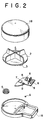
- Figs. 1 to 3 show an arrangement of a prior art brushless motor of the type referred to. More specifically, Fig. 1 shows a cross-sectional view of the prior art brushless motor showing an array of parts in the motor, Fig. 2 is an exploded perspective view of the parts of the motor, and Fig. 3 is a block diagram of the brushless motor.
- a casing 1 comprises a lower casing 1A and an upper casing 1B.
- Rotatably supported within the casing 1 is a rotor 2.
- Mounted on the bottom of the rotor 2 are permanent magnets 3 and 4 at positions symmetrical with respect to the center of the rotor 2.
- a coil 5 is mounted on the lower casing 1A.
- a magnet 6 is disposed to the lower casing 1A to position the rotor 2 at its initial position between the permanent magnets 3 and 4.
- the magnet 6 for positioning the rotor 2 at its initial position has the same polarity as that of the permanent magnets 3 and 4, which results in that the rotor 2 stops at its balanced position because the magnets repel each other.
- a magnetic sensor 7 such as a Hall effect element is mounted together with another electronic part 8 on a substrate 9 which in turn is disposed on the lower casing 1A.
- the magnetic sensor 7 is located at such a position as to be subjected to the influence of magnetic force of the permanent magnets 3 and 4 of the rotor 2.
- the substrate 9 having such parts mounted thereon is disposed on the lower casing 1A and then molded with resin material 10.
- a switching element 11 as a transistor is inserted between the coil 5 and the power source.
- the switching element 11 is connected with a current limiting element 12 such as a resistor which in turn is connected with an output terminal of the magnetic sensor 7. That is, the magnetic sensor 7 detects the positions of the permanent magnets 3 and 4 and generates an output signal that is sent to the switching element 11.
- the switching element 11 controls supply of a current to the coil 5 on the basis of the output signal received from the magnetic sensor 7.
- reference numeral 13 denotes a constant-voltage diode, 14 a resistor.
- a force resisting the movement of the rotor 2 trying to continuously coast exists as a repulsive force between the magnet 6 for positioning of the initial position of the rotor 2 and the permanent magnets 3 and 4 of the rotor 2, and the magnetic sensor 7 has a hysteresis width (which will be referred to as the BW, hereinafter) between a detection level (which will be referred to as the BH-L, hereinafter) changing from its detection off to detection on and a detection level (which will be referred to as the BL-H, hereinafter) changing from its detection on to detection off.
- BW hysteresis width
- the rotor 2 loses an attractive force caused by the coil 5 at the BL-H and is subjected to the influence of the repulsive force of the magnet 6 for positioning of the initial position of the rotor 2 to thereby start to reversely rotate, the rotor 2 returns to the BH-L and again normally rotates under the influence of the attractive force of the coil 5, which is repeated several time. After this, acceleration obtained during a period between the BL-L and BL-H causes the rotor 2 to overcome the repulsive force of the magnet 6 for positioning of the initial position of the rotor 2.
- the current-level technique of suppressing variations in the BW of the magnetic sensor has its limit and thus it has been impossible to solve the problem.
- a brushless motor which comprises a rotor having permanent magnets, a coil for rotating the rotor, a switching element inserted between the coil and a power source, a magnetic sensor for detecting a position of one of the permanent magnets of the rotor to control switching operation of the switching element, a current limiting element inserted between the magnetic sensor and the switching element, and a delay circuit inserted between the current limiting element and the magnetic sensor or between the current limiting element and the switching element.
- the present invention is provided with a timer circuit which conducts the switching element for a constant time at the time of turning on the power source.
- the delay circuit causes the switching element to be turned on even after the turning off of the magnetic sensor at the BL-H; whereas, the delay circuit causes the switching element to be turned off even after the turning on of the magnetic sensor at the BH-L.
- the apparent hysteresis width BW of the magnetic sensor is broadened so that an acceleration acquired during the apparent hysteresis width BW enables the rotor to overcome the repulsive force and rotate normally, thereby eliminating the influence of variations in the BW of the magnetic sensor.
- the timer circuit is provided for conducting the switching element for the constant time at the time of turning on the power source, so that, even when one of the permanent magnets of the rotor is stopped immediately above the initial-position positioning magnet of the rotor though this is very rare, the conduction of the switching element for the constant time at the time of turning on the power source causes the rotor to be moved by the attractive force of the coil, thereby ensuring that the rotor is returned to its initial position determined by the repulsive force of the initial-position positioning magnet of the rotor and thus any failure of starting the rotor can be avoided.
- a start control circuit in the motor which conducts the switching element for a predetermined time independently of control of the magnetic sensor at the time of turning on the power source, makes the switching element non-conductive for a predetermined time thereafter and further thereafter for being made independent of the control of the switching element.
- the switching element is first conducted for the constant time (about 10 seconds) so that, even when the rotor is previously rotated, the rotor is subjected to a braking by the attractive force of the coil and to a complete stoppage.
- Fig. 4 shows a circuit diagram of a brushless motor in accordance with an embodiment of the present invention
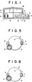
- Fig. 5 is a diagram for explaining the operational principle of the motor
- Fig. 6 is a specific circuit diagram of the motor.
- the same parts as those in the prior art motor in Figs. 1 to 3 are denoted by the same reference numerals.
- a delay circuit 15, which is inserted between the current limiting element 12 and the magnetic sensor 7, acts to prolong, in addition to the BW of the magnetic sensor 7, the on period of the switching element 11 to lengthen the energization period of the coil 5, only when the rotor 2 is vibrating as overcome by the repulsive force of the magnet for positioning of the initial position of the rotor.
- the delay circuit 15, as shown in Fig. 6, comprises transistors Q151 and Q152, diodes D151 and D152, resistors R151 and R152 and a capacitor C151.
- the delay circuit 15 may be inserted between the current limiting element 12 and the switching element 11.
- a timer circuit 16 is provided, when the power source is turned on, for causing the current limiting element 12 to supply a current to the switching element 11 for a predetermined time.
- the magnetic sensor 7 when the permanent magnet 4 is positioned above the magnetic sensor 7 as shown in Fig. 5, the magnetic sensor 7 generates an on-state output and the switching element 11 is turned on as delayed by a predetermined time, so that a current flows through the coil 5 which develops a torque for attracting the permanent magnet 3, whereby the rotor 2 is rotated.
- the permanent magnet 4 As the permanent magnet 3 is moved close toward the coil 5, the permanent magnet 4 is moved away from the magnetic sensor 7, so that the magnetic sensor 7 generates an off-state output and the switching element 11 is turned off as delayed by a predetermined time therefrom.
- the supply of the current to the coil 5 is stopped so that an attractive force between the permanent magnet 3 and the coil 5 disappears, whereby the rotor 2 is coasting.
- the permanent magnets 3 and 4 are put in the mutually opposite positions to the above and continuously perform the similar movement to the above.
- the delay circuit 15 provides a delay time in addition to the hysteresis width BW of the magnetic sensor 7 between its detection level BH-L changing from its detection off to detection on and its detection level BL-H changing from its detection on to detection off.
- the coil 5 is energized for a long time when compared to the prior art, so that, when the rotor 2 loses the attractive force of the coil 5 at the detection level BL-H and yields the repulsive force of the magnet 6 for positioning of the initial position of the rotor 2 to thereby start to reversely rotate, the rotor 2 returns to the detection level BH-L and again starts to normally rotate under the influence of the attractive force of the coil 5, which is repeated several times.
- an acceleration obtained during a period corresponding to a sum of a duration from the BH-L to the BL-H and the delay time of the delay circuit 15 causes the rotor 2 to overcome the repulsive force of the magnet 6 for positioning of the initial position of the rotor 2.
- the delay time of the delay circuit 15 is set to be constant, the vibration of the rotor 2 is increased in amplitude with the gradual increase of the acceleration and eventually can overcome the repulsive force of the magnet 6 for positioning of the initial position.
- the delay time based on the BH-L and BL-H takes place in the same rotational direction as the rotor 2, whereby this does not substantially affect the energization period of the coil 5 and therefore the motor can be designed according to the conventional design specifications.
- the turning on of the power source causes the transistor Q161 to be turned on for a constant time (about 10ms) determined by a resistor R161 and a capacitor C161 making up the timer circuit 16, whereby the switching element 11 is turned on so that the coil 5 is put in its energized state so as to attract the permanent magnet 3 or 4 of the rotor 2, thus resulting in that the permanent magnet 3 or 4 of the rotor 2 is moved from its immediate above position of the initial-position positioning magnet 6, thereby avoiding the disabled rotation of the motor.
- reference symbol D161 denotes a diode, C a capacitor, R a resistor, R a resistor, D1 and D2 diodes respectively.
- the present embodiment corresponds to an improvement in the foregoing first embodiment wherein mainly the timer circuit section is improved and a start control function is added of controlling the switching element 11 independently of the control of the switching element 11 by means of the magnetic sensor 7.
- This start control function may be arranged as combined with the delay circuit section of the foregoing embodiment.
- Fig. 7 is a circuit diagram of a brushless motor in accordance with another embodiment of the present invention
- Fig. 8 is a diagram for explaining the operation of the motor
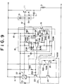
- Fig. 9 is a specific circuit diagram of the motor.
- a start control circuit 18 functions to turn on and off a switching element 19 for controlling the switching element 11 and also to turn on and off a switching element 20 for controlling the operation of the magnetic sensor 7. More specifically, the start control circuit 18, as shown in Fig.
- FIG. 9 comprises comparators IC181 and IC182, diodes D181, D182, D183 and D184, resistors R181 to R188 and capacitors C181 and C182.
- a charging current flows through the capacitor C181, the resistor R186, the diode D183 and the resistor R187 to thereby increase gradually a voltage across the capacitor C181.
- a reference voltage which is determined by the voltage division ratio of the resistors R183 and R184. Voltages at respective minus terminals of the comparators IC181 and IC182 are increased with the voltage across the capacitor C181.
- the switching element 11 is forcingly turned off.
- the capacitor C181 is further charged to such an extent that the voltage at the minus terminal of the comparator IC181 exceeds the above reference voltage, the output of the comparator IC181 at its output terminal is changed from its high level to low.
- the comparator IC182 receives at tis minus terminal a voltage which is determined by the voltage division ratio of the resistors R185 and R186 and which is previously set to be smaller than the above reference voltage. As a result, the output of the comparator IC182 at the output terminal is changed from its high level to low.
- the switching element 20 is switched to the on state and the switching element 19 remains off because of its low level via the diode D183. Accordingly, the switching element 11 is released from its forcing on/off state and is operated according to the on/off operation of the magnetic sensor 7.
- a constant-voltage diode 13 which is applied with the voltage of the power source via a resistor 15, is provided for the stabilization of operation of the start control circuit 18.
- Diodes 21 and 22 are provided for prevention of any surging current of the magnetic sensor 7, while a surge prevention circuit 23 is provided to protect circuits and elements other than the switching element 11.
- a current limiting resistor 14 is connected in a power source line for driving the magnetic sensor 7. More specifically, the surge prevention circuit 23 comprises transistors Q231 and Q232, and resistors R231, R232 and R233.
- the permanent magnets 3 and 4 are put in the mutually opposite positions to the above and continuously perform the similar movement to the above.
- a force resisting the movement of the rotor 2 trying to coast continuously exists as a repulsive force between the magnet 6 for positioning of the initial position of the rotor 2 and the permanent magnets 3 and 4 of the rotor 2. Therefore, there is a danger that the permanent magnet 3 or 4 of the rotor 2 is stopped immediately above the initial-position positioning magnet 6 of the rotor 2.
- the present embodiment is arranged so that the turning on of the power source causes the switching element 11 to be forcingly turned on for a constant time (about 10 seconds).
- the magnetic sensor 7 When the rotor 2 is stopped at its initial position and is to be rotated under control of the magnetic sensor 7 through the switching element 11, the magnetic sensor 7 is in the detection on mode at the initial position of the rotor 2 so that, while the rotor 2 is rotated and the magnetic sensor 7 is changed from its detection on to detection off, the rotor 2 can acquire a sufficient rotary torque, with the result that the rotor 2 can overcome the repulsive force of the initial-position positioning magnet 6 of the rotor 2 and can continuously rotate.
- the current on period of the coil during which a current flows therethrough can be prolonged by an amount corresponding to a sum of the delay time of the delay circuit and the hysteresis width BW determined by the performance of the magnetic sensor, only when the rotor is vibrating and it is necessary for the rotor to overcome the repulsive force of the initial-position positioning magnet of the rotor.
- a brushless motor wherein the rotor can be rotated without yielding the repulsive force of the initial-position positioning magnet of the rotor and which also can be immune to the influence of variations in the BW of the magnetic sensor.
- the start control circuit since the rotation of the rotor can be started from its initial position after application of the power source voltage, the rotor can be rotated without yielding the repulsive force of the initial-position positioning magnet of the rotor and without being subjected to the influence of variations in the BW of the magnetic sensor.
Landscapes
- Engineering & Computer Science (AREA)
- Power Engineering (AREA)
- Microelectronics & Electronic Packaging (AREA)
- Control Of Motors That Do Not Use Commutators (AREA)
- Brushless Motors (AREA)
Priority Applications (1)
| Application Number | Priority Date | Filing Date | Title |
|---|---|---|---|
| EP93113407A EP0574039B1 (fr) | 1990-07-31 | 1991-07-29 | Moteur sans balai |
Applications Claiming Priority (4)
| Application Number | Priority Date | Filing Date | Title |
|---|---|---|---|
| JP203300/90 | 1990-07-31 | ||
| JP203299/90 | 1990-07-31 | ||
| JP2203300A JPH088769B2 (ja) | 1990-07-31 | 1990-07-31 | 単相ブラシレスモータの半波駆動回路 |
| JP2203299A JPH0488860A (ja) | 1990-07-31 | 1990-07-31 | ブラシレスモータ |
Related Child Applications (1)
| Application Number | Title | Priority Date | Filing Date |
|---|---|---|---|
| EP93113407.6 Division-Into | 1993-08-23 |
Publications (3)
| Publication Number | Publication Date |
|---|---|
| EP0469822A2 true EP0469822A2 (fr) | 1992-02-05 |
| EP0469822A3 EP0469822A3 (en) | 1992-04-29 |
| EP0469822B1 EP0469822B1 (fr) | 1994-12-14 |
Family
ID=26513857
Family Applications (2)
| Application Number | Title | Priority Date | Filing Date |
|---|---|---|---|
| EP91306916A Expired - Lifetime EP0469822B1 (fr) | 1990-07-31 | 1991-07-29 | Moteur sans balai |
| EP93113407A Expired - Lifetime EP0574039B1 (fr) | 1990-07-31 | 1991-07-29 | Moteur sans balai |
Family Applications After (1)
| Application Number | Title | Priority Date | Filing Date |
|---|---|---|---|
| EP93113407A Expired - Lifetime EP0574039B1 (fr) | 1990-07-31 | 1991-07-29 | Moteur sans balai |
Country Status (3)
| Country | Link |
|---|---|
| US (1) | US5157311A (fr) |
| EP (2) | EP0469822B1 (fr) |
| DE (2) | DE69105855T2 (fr) |
Cited By (2)
| Publication number | Priority date | Publication date | Assignee | Title |
|---|---|---|---|---|
| EP0639884A1 (fr) * | 1993-08-17 | 1995-02-22 | Bayerische Motoren Werke Aktiengesellschaft | Unité de commande électrique |
| EP1271752A1 (fr) * | 2001-06-13 | 2003-01-02 | HSU, Chun-Pu | Dispositif permettant d'augmenter la vitesse de rotation d'un moteur à aimants permanents |
Families Citing this family (7)
| Publication number | Priority date | Publication date | Assignee | Title |
|---|---|---|---|---|
| DE3942003A1 (de) * | 1989-12-20 | 1991-06-27 | Thomson Brandt Gmbh | Verfahren und vorrichtung zur steuerung eines elektronisch kommutierten motors |
| US5285135A (en) * | 1992-09-23 | 1994-02-08 | Sgs-Thomson Microelectronics, Inc. | Automatic adjustment of commutation delay for brushless DC motor for improved efficiency |
| US6850019B2 (en) * | 2003-06-12 | 2005-02-01 | Mcmillan Electric Company | Single coil, direct current permanent magnet brushless motor with voltage boost |
| JP4454328B2 (ja) * | 2004-01-29 | 2010-04-21 | 三洋電機株式会社 | モータ駆動装置、集積回路、モータ駆動方法 |
| JP4904996B2 (ja) * | 2006-08-28 | 2012-03-28 | セイコーエプソン株式会社 | ブラシレスモータ |
| JP5944196B2 (ja) * | 2012-03-28 | 2016-07-05 | ミネベア株式会社 | モータ駆動制御装置 |
| JP2016082669A (ja) * | 2014-10-15 | 2016-05-16 | 日本電産株式会社 | シーリングファン用モータ、およびシーリングファン |
Family Cites Families (20)
| Publication number | Priority date | Publication date | Assignee | Title |
|---|---|---|---|---|
| US3402337A (en) * | 1966-06-13 | 1968-09-17 | American District Telegraph Co | Electrical motor starting arrangement |
| DE2415347C3 (de) * | 1973-03-31 | 1978-10-05 | Sansui Electric Co., Ltd., Tokio | Selbsterregender Gleichstrommotor |
| DE2806595C2 (de) * | 1978-02-16 | 1987-11-12 | Danfoss A/S, 6430 Nordborg | Steuerschaltung für einen selbstanlaufenden Elektromotor mit einem Dauermagnetläufer |
| CH658348A5 (de) * | 1979-11-30 | 1986-10-31 | Papst Motoren Kg | Zweipulsiger kollektorloser gleichstrommotor. |
| US4686437A (en) * | 1980-06-20 | 1987-08-11 | Kollmorgen Technologies Corporation | Electromechanical energy conversion system |
| US4429262A (en) * | 1980-09-12 | 1984-01-31 | Technicare Corporation | Three phase motor oscillatory servo control |
| US4525657A (en) * | 1983-03-09 | 1985-06-25 | Matsushita Electric Industrial Co., Ltd. | Torque ripple compensation circuit for a brushless D.C. motor |
| JPS6082092A (ja) * | 1983-10-11 | 1985-05-10 | Sanyo Electric Co Ltd | 電動機の起動方法 |
| JPS6091853A (ja) * | 1983-10-24 | 1985-05-23 | Nippon Denso Co Ltd | 無整流子電動機 |
| US4588912A (en) * | 1983-10-24 | 1986-05-13 | Nippondenso Co., Ltd. | D.C. brushless motor with an improved yoke |
| JPS6154860A (ja) * | 1984-08-24 | 1986-03-19 | Nippon Denso Co Ltd | 無整流子電動機 |
| DE3342986A1 (de) * | 1983-11-28 | 1985-06-05 | Papst-Motoren GmbH & Co KG, 7742 St Georgen | Kollektorloser gleichstrommotor |
| JPS60160390A (ja) * | 1984-01-30 | 1985-08-21 | Secoh Giken Inc | 1相の半導体電動機 |
| JPS60162167A (ja) * | 1984-02-03 | 1985-08-23 | 松下電器産業株式会社 | 間欠作動化学ヒ−トポンプ装置 |
| US4584505A (en) * | 1984-06-14 | 1986-04-22 | Yeongchoon Chung | Torque-speed control system for asynchronous D.C. brushless motor |
| US4631459A (en) * | 1984-12-25 | 1986-12-23 | Matsushita Electric Industrial Co., Ltd. | Brushless DC motor |
| EP0282598B1 (fr) * | 1986-08-06 | 1993-03-17 | Fujitsu Limited | SYSTEME D'ENTRAINEMENT D'UN MOTEUR c.c. |
| BR8805485A (pt) * | 1988-10-17 | 1990-06-05 | Brasil Compressores Sa | Circuito eletronico de controle para motor de corrente continua sem escovas |
| US4897583A (en) * | 1989-03-07 | 1990-01-30 | Sundstrand Corporation | Variable speed variable torque brushless DC motor |
| JPH06103995B2 (ja) * | 1989-05-31 | 1994-12-14 | 日本ビクター株式会社 | センサレス方式ブラシレスモータ |
-
1991
- 1991-07-26 US US07/736,591 patent/US5157311A/en not_active Expired - Fee Related
- 1991-07-29 EP EP91306916A patent/EP0469822B1/fr not_active Expired - Lifetime
- 1991-07-29 DE DE69105855T patent/DE69105855T2/de not_active Expired - Fee Related
- 1991-07-29 DE DE69115718T patent/DE69115718T2/de not_active Expired - Fee Related
- 1991-07-29 EP EP93113407A patent/EP0574039B1/fr not_active Expired - Lifetime
Cited By (2)
| Publication number | Priority date | Publication date | Assignee | Title |
|---|---|---|---|---|
| EP0639884A1 (fr) * | 1993-08-17 | 1995-02-22 | Bayerische Motoren Werke Aktiengesellschaft | Unité de commande électrique |
| EP1271752A1 (fr) * | 2001-06-13 | 2003-01-02 | HSU, Chun-Pu | Dispositif permettant d'augmenter la vitesse de rotation d'un moteur à aimants permanents |
Also Published As
| Publication number | Publication date |
|---|---|
| DE69115718T2 (de) | 1996-08-29 |
| DE69115718D1 (de) | 1996-02-01 |
| EP0574039B1 (fr) | 1995-12-20 |
| DE69105855T2 (de) | 1995-07-20 |
| DE69105855D1 (de) | 1995-01-26 |
| EP0469822B1 (fr) | 1994-12-14 |
| US5157311A (en) | 1992-10-20 |
| EP0469822A3 (en) | 1992-04-29 |
| EP0574039A1 (fr) | 1993-12-15 |
Similar Documents
| Publication | Publication Date | Title |
|---|---|---|
| US4553075A (en) | Simple brushless DC fan motor with reversing field | |
| US4365187A (en) | Brushless D.C. motor | |
| KR930005880B1 (ko) | 자동 재시동 또는 커트-인 기능을 갖고 있는 모터 제어회로. | |
| US5675226A (en) | Control circuit for an synchronous electric motor of the brushless type | |
| US6982532B2 (en) | Electric machine | |
| US4734627A (en) | Brushless D.C. motor having two conductors per phase energized alternately by complementary-conductivity-type semiconductors controlled by the same rotor-position signal, at times modified by a compensating technique | |
| US20070152612A1 (en) | Motor controller | |
| US5157311A (en) | Brushless motor | |
| US4588912A (en) | D.C. brushless motor with an improved yoke | |
| AU2005300081B2 (en) | Apparatus for securing a bobbin of a reluctance machine | |
| US6429615B2 (en) | Electronically commutated DC motor | |
| US6396226B2 (en) | Electronically commutated DC motor | |
| CA2575725C (fr) | Systeme et procede de redemarrage d'un moteur a reluctance commute apres un cycle rapide d'alimentation | |
| JP3124474U (ja) | ブラシレス直流モータの制御装置 | |
| US6731086B2 (en) | Motor driving device | |
| JP4026741B2 (ja) | 過電流保護回路を有するブラシレスモータの駆動回路 | |
| JP4444511B2 (ja) | 電子コミュテーション式モータ | |
| US20020145397A1 (en) | Electronically commutated electric motor | |
| US3538407A (en) | Commutating circuit for a commutatorless dc miniature motor | |
| CN103503306B (zh) | 用于控制电动机中的脉冲宽度调制的方法和装置 | |
| JPH04161092A (ja) | ブラシレスモータ制御装置 | |
| JPH088769B2 (ja) | 単相ブラシレスモータの半波駆動回路 | |
| JPH0552131B2 (fr) | ||
| JP3217387B2 (ja) | ファン装置 | |
| JP3263993B2 (ja) | センサレスモータの起動方法 |
Legal Events
| Date | Code | Title | Description |
|---|---|---|---|
| PUAI | Public reference made under article 153(3) epc to a published international application that has entered the european phase |
Free format text: ORIGINAL CODE: 0009012 |
|
| AK | Designated contracting states |
Kind code of ref document: A2 Designated state(s): DE GB |
|
| PUAL | Search report despatched |
Free format text: ORIGINAL CODE: 0009013 |
|
| AK | Designated contracting states |
Kind code of ref document: A3 Designated state(s): DE GB |
|
| 17P | Request for examination filed |
Effective date: 19920610 |
|
| 17Q | First examination report despatched |
Effective date: 19920918 |
|
| GRAA | (expected) grant |
Free format text: ORIGINAL CODE: 0009210 |
|
| AK | Designated contracting states |
Kind code of ref document: B1 Designated state(s): DE GB |
|
| XX | Miscellaneous (additional remarks) |
Free format text: TEILANMELDUNG 93113407.6 EINGEREICHT AM 29/07/91. |
|
| REF | Corresponds to: |
Ref document number: 69105855 Country of ref document: DE Date of ref document: 19950126 |
|
| PLBE | No opposition filed within time limit |
Free format text: ORIGINAL CODE: 0009261 |
|
| STAA | Information on the status of an ep patent application or granted ep patent |
Free format text: STATUS: NO OPPOSITION FILED WITHIN TIME LIMIT |
|
| 26N | No opposition filed | ||
| PGFP | Annual fee paid to national office [announced via postgrant information from national office to epo] |
Ref country code: DE Payment date: 20010723 Year of fee payment: 11 |
|
| PGFP | Annual fee paid to national office [announced via postgrant information from national office to epo] |
Ref country code: GB Payment date: 20010725 Year of fee payment: 11 |
|
| REG | Reference to a national code |
Ref country code: GB Ref legal event code: IF02 |
|
| PG25 | Lapsed in a contracting state [announced via postgrant information from national office to epo] |
Ref country code: GB Free format text: LAPSE BECAUSE OF NON-PAYMENT OF DUE FEES Effective date: 20020729 |
|
| PG25 | Lapsed in a contracting state [announced via postgrant information from national office to epo] |
Ref country code: DE Free format text: LAPSE BECAUSE OF NON-PAYMENT OF DUE FEES Effective date: 20030201 |
|
| GBPC | Gb: european patent ceased through non-payment of renewal fee |
Effective date: 20020729 |