EP0469874B1 - Appareil de reproduction - Google Patents
Appareil de reproduction Download PDFInfo
- Publication number
- EP0469874B1 EP0469874B1 EP91306999A EP91306999A EP0469874B1 EP 0469874 B1 EP0469874 B1 EP 0469874B1 EP 91306999 A EP91306999 A EP 91306999A EP 91306999 A EP91306999 A EP 91306999A EP 0469874 B1 EP0469874 B1 EP 0469874B1
- Authority
- EP
- European Patent Office
- Prior art keywords
- recorded
- date
- music
- data
- main data
- Prior art date
- Legal status (The legal status is an assumption and is not a legal conclusion. Google has not performed a legal analysis and makes no representation as to the accuracy of the status listed.)
- Expired - Lifetime
Links
Images


Classifications
-
- G—PHYSICS
- G11—INFORMATION STORAGE
- G11B—INFORMATION STORAGE BASED ON RELATIVE MOVEMENT BETWEEN RECORD CARRIER AND TRANSDUCER
- G11B27/00—Editing; Indexing; Addressing; Timing or synchronising; Monitoring; Measuring tape travel
- G11B27/10—Indexing; Addressing; Timing or synchronising; Measuring tape travel
- G11B27/19—Indexing; Addressing; Timing or synchronising; Measuring tape travel by using information detectable on the record carrier
- G11B27/28—Indexing; Addressing; Timing or synchronising; Measuring tape travel by using information detectable on the record carrier by using information signals recorded by the same method as the main recording
- G11B27/30—Indexing; Addressing; Timing or synchronising; Measuring tape travel by using information detectable on the record carrier by using information signals recorded by the same method as the main recording on the same track as the main recording
- G11B27/3027—Indexing; Addressing; Timing or synchronising; Measuring tape travel by using information detectable on the record carrier by using information signals recorded by the same method as the main recording on the same track as the main recording used signal is digitally coded
- G11B27/3036—Time code signal
-
- G—PHYSICS
- G11—INFORMATION STORAGE
- G11B—INFORMATION STORAGE BASED ON RELATIVE MOVEMENT BETWEEN RECORD CARRIER AND TRANSDUCER
- G11B15/00—Driving, starting or stopping record carriers of filamentary or web form; Driving both such record carriers and heads; Guiding such record carriers or containers therefor; Control thereof; Control of operating function
- G11B15/02—Control of operating function, e.g. switching from recording to reproducing
- G11B15/05—Control of operating function, e.g. switching from recording to reproducing by sensing features present on or derived from record carrier or container
- G11B15/087—Control of operating function, e.g. switching from recording to reproducing by sensing features present on or derived from record carrier or container by sensing recorded signals
-
- G—PHYSICS
- G11—INFORMATION STORAGE
- G11B—INFORMATION STORAGE BASED ON RELATIVE MOVEMENT BETWEEN RECORD CARRIER AND TRANSDUCER
- G11B27/00—Editing; Indexing; Addressing; Timing or synchronising; Monitoring; Measuring tape travel
- G11B27/10—Indexing; Addressing; Timing or synchronising; Measuring tape travel
- G11B27/102—Programmed access in sequence to addressed parts of tracks of operating record carriers
- G11B27/107—Programmed access in sequence to addressed parts of tracks of operating record carriers of operating tapes
-
- G—PHYSICS
- G11—INFORMATION STORAGE
- G11B—INFORMATION STORAGE BASED ON RELATIVE MOVEMENT BETWEEN RECORD CARRIER AND TRANSDUCER
- G11B27/00—Editing; Indexing; Addressing; Timing or synchronising; Monitoring; Measuring tape travel
- G11B27/10—Indexing; Addressing; Timing or synchronising; Measuring tape travel
- G11B27/19—Indexing; Addressing; Timing or synchronising; Measuring tape travel by using information detectable on the record carrier
- G11B27/28—Indexing; Addressing; Timing or synchronising; Measuring tape travel by using information detectable on the record carrier by using information signals recorded by the same method as the main recording
- G11B27/30—Indexing; Addressing; Timing or synchronising; Measuring tape travel by using information detectable on the record carrier by using information signals recorded by the same method as the main recording on the same track as the main recording
- G11B27/3027—Indexing; Addressing; Timing or synchronising; Measuring tape travel by using information detectable on the record carrier by using information signals recorded by the same method as the main recording on the same track as the main recording used signal is digitally coded
- G11B27/3063—Subcodes
-
- G—PHYSICS
- G11—INFORMATION STORAGE
- G11B—INFORMATION STORAGE BASED ON RELATIVE MOVEMENT BETWEEN RECORD CARRIER AND TRANSDUCER
- G11B27/00—Editing; Indexing; Addressing; Timing or synchronising; Monitoring; Measuring tape travel
- G11B27/10—Indexing; Addressing; Timing or synchronising; Measuring tape travel
- G11B27/34—Indicating arrangements
-
- G—PHYSICS
- G11—INFORMATION STORAGE
- G11B—INFORMATION STORAGE BASED ON RELATIVE MOVEMENT BETWEEN RECORD CARRIER AND TRANSDUCER
- G11B2220/00—Record carriers by type
- G11B2220/90—Tape-like record carriers
-
- G—PHYSICS
- G11—INFORMATION STORAGE
- G11B—INFORMATION STORAGE BASED ON RELATIVE MOVEMENT BETWEEN RECORD CARRIER AND TRANSDUCER
- G11B2220/00—Record carriers by type
- G11B2220/90—Tape-like record carriers
- G11B2220/91—Helical scan format, wherein tracks are slightly tilted with respect to tape direction, e.g. VHS, DAT, DVC, AIT or exabyte
- G11B2220/913—Digital audio tape [DAT] format
Definitions
- the present invention relates to a recording and/or reproducing apparatus, and is suitably applied to a rotary head type digital audio tape recorder (DAT), for example.
- DAT digital audio tape recorder
- each of the recording tracks of a magnetic tape recorded in the conventional DAT format there is formed a sub-data portion which records start information representing the heads of the pieces of music, program time, absolute time, calender information, etc. in addition to a main data portion having the pieces of music or the like recorded by digital audio signals.
- each piece of start information is recorded as data with logic "H” level in the head of each piece of music as a record unit for about 9 seconds.
- program time relative elapsed time between pieces of start information with logic "H” level is recorded taking after-record editing into consideration.
- the absolute time elapsed time from the head of the magnetic tape, for example, is recorded, and in the calender information, the recording times are recorded as date and time information including year, month, day, hour, minute and second.
- the DAT has a music scan function: start information is searched by sequentially fast forward reproducing the magnetic tape from the head thereof; and the pieces of music are sequentially reproduced from the timing of detecting each piece of the start information only for a predetermined period of time (10 seconds, for example).
- start information is searched by sequentially fast forward reproducing the magnetic tape from the head thereof; and the pieces of music are sequentially reproduced from the timing of detecting each piece of the start information only for a predetermined period of time (10 seconds, for example).
- a magnetic tape may have programs, each of which consists of pieces of music, recorded on it.
- the system is enhanced in utility by searching and reproducing heads of programs recorded on the magnetic tape.
- the music scan function previously described can merely scan all the music irrespective of the programs, and hence it is still insufficient in facility.
- an aim of the present invention is to provide a recording and/or reproducing system which is capable of markedly improving facility for the user by performing scan reproduction in each of record information units which are different in record time using date information.
- a reproducing apparatus for reproducing data from a recording medium having recorded thereon data and date information (CAL1,CAL2) representative of the date said data was recorded, the apparatus comprising means for playing back said data and means for detecting said date information, characterised by : means for sequentially searching the record medium and for controlling the playback means to playback the data on the medium for a predetermined period when it is detected that the date information (CAL2) has changed from the immediately previous date in formation (CAL1) by a predetermined value or more.
- the record medium 2 is played back for the predetermined period of time from a point of time when it is detected by sequentially searching the record medium 2 that the date information CAL2 has changed by the predetermined value or more from the immediately previous date information CAL1, the date information CAL2 being recorded in the whole areas of the recording medium 2.
- This enables scan reproduction to be achieved in the unit of information unit PRA, PRB, information units being different in point of record time from each other.
- FIG. 1, 1 indicates a general configuration of a DAT according to the present invention, in which a magnetic tape 2 is wrapped over a drum 3.
- the audio data recorded on the magnetic tape 2 is read out by a rotary head 4 mounted to the drum 3, and is inputted as playback signals SPB to a playback signal processing circuit 5.
- the playback signal processing circuit 5 includes a reproduction amplification circuit, an equalizer circuit, binarization circuit, etc., and read-out digital data DPB obtained by these components is inputted to a digital signal processing circuit 6.
- the digital signal processing circuit 6 includes a central processing unit (CPU), a memory, a demodulation circuit, an error detection correction circuit, a digital-to-analog conversion circuit, etc., and demodulates the read out digital data DPB using the memory as well as performs error detection and correction.
- the resulting analog signals are outputted as reproduced audio signals ADPB to the outside.
- the digital signal processing circuit 6 demodulates the sub-data portion contained in the read out digital data DPB, and thereby sends out display data DDSP representing start information, absolute time, program time, etc. to an operation unit 7.
- command data DCMD which corresponds to the operated button is inputted to the digital signal processing circuit 6, and thereby the whole DAT 1 performs operation, such as playback, record, fast forwarding, reversing, pause, and stop, in response to the operated button.
- the operation unit 7 is further provided with a music scan button and a date button.
- a music scan button and a date button By simultaneously operating the music scan button and the play button the DAT 1 achieves the music scan processing. Furthermore, by simultaneously operating the music scan button, the date button and the play button, the DAT 1 performs the date music scan processing using the calender information.
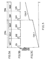
- main data areas ARPCM each having audio data produced are centrally provided; the main data areas ARPCM are each provided at the front and rear thereof with first and second ATF record areas ARATF1 and ARAFT2, respectively; and furthermore, externally of the ATF record areas ARATF1 and ARATF2 there are provided with first and second subdata portion areas ARSB1 and ARSB2.
- ARSB2 there is recorded sequentially as the subdata calender information CAL1, CAL2 (FIG. 3C) which represents a time when the music MA1, MA2, MA3, MB1, MB2 is recorded on the magnetic tape 2.
- the pieces of the music MA1, MA2 and MA3 are recorded as a first program PRA whereas the pieces of the music MB1 and MB2 are recorded as a second program PRB which is discontinuous to the first program PRA.
- a step of time is produced between the calender information CAL1 of the music MA3 and the calender information CAL2 of the music MB1.
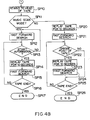
- command data DCMD representing that the music scan button or the date button has been operated is inputted to the digital signal processing circuit 6 from the operation unit 7, the digital signal processing circuit 6 executes a tape scan routine RT0 shown in FIGS. 4A and 4B, so that a music scan processing using the start information or a date music scan processing using the calender information is executed.
- the CPU of the digital signal processing circuit 6 enters the tape scan routine RT0, and then in the next step SP1 it judges whether or not the operated button is the music scan button.
- the CPU proceeds to the step SP2, where the music scan mode is set in the inner memory, and then, the CPU goes to the step SP3.
- the CPU directly goes to the step SP3.
- the CPU judges whether or not the operated button is the date button.
- the CPU goes to the step SP4, where it makes a judgement as to whether or not it is in the music scan mode by referring to the inner memory.
- step SP4 When in this step SP4 an affirmative result is obtained, the CPU goes to the step SP5, in which the music scan mode of the inner memory is reset. In the subsequent step SP6 the date music scan mode is set, and then the CPU proceeds to the step SP7.
- the CPU directly goes to the step SP7, and also when in the step SP4 a negative result is obtained, it directly proceeds to the step SP7.
- step SP7 the CPU judges whether or not the operated button is the play button.
- the CPU goes to the step SP8, where with reference to the inner memory a judgement is made as to whether or not it is in the music scan mode.
- step SP8 When a negative result is obtained in this step SP8, the CUP goes to the step SP9 where with reference to the inner memory a judgement is made as to whether or not it is in the date music scan mode. When an affirmative result is obtained here, the CPU goes to the step SP10.
- the CPU of the digital signal processing circuit 6 executes the steps SP1 to SP9 of the tape scan routine RT0 when the music scan button or the date button of the operation unit 7 is operated, and thereby it detects the buttons simultaneously operated.
- the music scan mode is set and the CPU goes to the step SP10.
- step SP10 the CPU rewinds the magnetic tape 2 to the head.
- step SP11 the CPU judges whether or not it is in the music scan mode by referring to the inner memory.
- the CPU goes to the step SP12, and starts the music scan processing using the start information ID.
- the CPU executes a fast-forward search of the magnetic tape 2, and then in the next step SP13 it judges whether or not the searched information is the start information ID. When a negative result is obtained, the CPU returns to the step SP12. When on the contrary an affirmative result is obtained, the CPU goes to the step SP14.
- step SP14 the CPU performs reproduction of the magnetic tape 2 for 10 seconds, and in the subsequent step SP15 executes a fast-forward search of the magnetic tape 2. Then, in the subsequent step SP16 it is judged whether or not the end of the tape is reached. When a negative result is obtained, the CPU returns to the step SP13. When on the contrary an affirmative result is obtained, the CPU goes to the step SP17, where the tape scan routine RT0 is finished.
- the CPU goes to the step SP20, in which the date music scan processing is started using the calender information CAL.
- step SP20 the CPU performs reproduction of the magnetic tape 2 for only 10 seconds, and in the subsequent step SP21 executes a fast-forward search of the magnetic tape 2.
- step SP22 it is judged whether or not there is a change point of date.
- the CPU refers to the calender information CAL 2 and calculates the difference between the calender information and the immediately previous calender information CAL1. When this difference is equal to or larger than a predetermined value, an affirmative result is obtained and then the CPU goes to the step SP23.
- step SP23 the CPU performs reproduction of the magnetic tape 2 for only 10 seconds, and then in the subsequent step SP24 executes a fast-forward search of the magnetic tape 2. Then, the CPU goes to the step SP25.
- step SP25 the CPU judges whether or not the end of the tape is reached. When a negative result is obtained in the step SP25, the CPU returns to the step SP22. When on the contrary an affirmative result is obtained, the CPU goes to the step SP26, where the tape scan routine RT0 is completed.
- the DAT1 executes the music scan processing using the start information ID, and thus the head portions of all the music MA1, MA2, MA3, MB1 and MB2 recorded on the magnetic tape 2 can be sequentially listened by scan reproduction on the basis of the start information.
- the DAT1 executes the date music scan processing using the calender information CAL, the head portion of the music MA1, MB1 of each program PRA, PRB recorded on the magnetic tape 2 can be sequentially listened by scan reproduction on the basis of the start information.
- the magnetic tape 2 is reproduced for a predetermined period of time from a point of time when it is detected by fast-forward search of the magnetic tape 2 that the calender information CAL2 recorded in the subdata portion areas ARSB1 and ARSB2 of the magnetic tape 2 has changed by the predetermined value or more from the immediately previous calender information CAL1.
- This can realize a DAT which is capable of scan reproducing each of programs PRA, PRB different in record time, and enables facility for the user to be markedly enhanced.
- the present invention is applied to DAT but the present invention is not limited to this and may be widely applied to recording and/or reproducing systems which use record media having date information recorded on the whole areas of the recording tracks.
Landscapes
- Indexing, Searching, Synchronizing, And The Amount Of Synchronization Travel Of Record Carriers (AREA)
- Signal Processing For Digital Recording And Reproducing (AREA)
Claims (8)
- Appareil de reproduction (1) pour reproduire des données d'un support d'enregistrement (2) sur lequel sont enregistrées des données principales et des informations de date (CAL1, CAL2) représentatives de la date à laquelle lesdites données ont été enregistrées, l'appareil comprenant des moyens pour lire lesdites données et des moyens pour détecter lesdites informations de date, caractérisé par :des moyens pour exécuter séquentiellement une recherche sur le support d'enregistrement (2) et pour commander les moyens de lecture afin de lire les données sur le support pendant une période prédéterminée quand il est détecté que les informations de date (CAL2) ont varié d'une valeur prédéterminée ou plus par rapport aux informations de date (CAL1) les précédant immédiatement.
- Appareil selon la revendication 1, dans lequel lesdites données principales sont représentatives d'informations sonores ou musicales.
- Appareil selon l'une quelconque des revendications 1 et 2, dans lequel lesdites données principales et lesdites informations de date sont composées de signaux numériques.
- Appareil selon l'une quelconque des revendications 1 à 3, dans lequel, lors de la recherche desdites informations de date, ledit support d'enregistrement est déplacé à une vitesse supérieure à celle pendant une reproduction normale desdites données principales.
- Appareil selon l'une quelconque des revendications 1 à 4, dans lequel ledit support d'enregistrement est constitué par une bande magnétique.
- Appareil selon l'une quelconque des revendications précédentes, dans lequel lesdits moyens de lecture sont commandés pour lire la partie de début desdites données principales pendant ladite période prédéterminée, de façon répétitive un nombre prédéterminé de fois.
- Appareil selon l'une quelconque des revendications précédentes, dans lequel au moins des premières, deuxièmes et troisièmes données principales et des premières, deuxièmes et troisièmes informations de date sont enregistrées sur ledit support d'enregistrement, lesdites premières, deuxièmes et troisièmes informations de date étant représentatives du temps auquel lesdites premières, deuxièmes et troisièmes données principales ont été enregistrées sur ledit support d'enregistrement, l'appareil comprenant en outre ;des moyens pour réexécuter séquentiellement une recherche sur ledit support d'enregistrement après la fin de la reproduction par lesdits premiers moyens de reproduction et pour commander les moyens de lecture afin de changer de valeur d'au moins une quantité prédéterminée.
- Appareil selon la revendication 7, dans lequel lesdits moyens de lecture sont commandés pour reproduire la partie de début desdites troisièmes données principales pendant la seconde période prédéterminée, de façon répétitive un nombre prédéterminé de fois.
Applications Claiming Priority (2)
| Application Number | Priority Date | Filing Date | Title |
|---|---|---|---|
| JP204573/90 | 1990-07-31 | ||
| JP2204573A JPH0490181A (ja) | 1990-07-31 | 1990-07-31 | 記録再生装置 |
Publications (3)
| Publication Number | Publication Date |
|---|---|
| EP0469874A2 EP0469874A2 (fr) | 1992-02-05 |
| EP0469874A3 EP0469874A3 (en) | 1993-01-20 |
| EP0469874B1 true EP0469874B1 (fr) | 1996-03-27 |
Family
ID=16492711
Family Applications (1)
| Application Number | Title | Priority Date | Filing Date |
|---|---|---|---|
| EP91306999A Expired - Lifetime EP0469874B1 (fr) | 1990-07-31 | 1991-07-30 | Appareil de reproduction |
Country Status (4)
| Country | Link |
|---|---|
| US (1) | US5253121A (fr) |
| EP (1) | EP0469874B1 (fr) |
| JP (1) | JPH0490181A (fr) |
| DE (1) | DE69118269T2 (fr) |
Families Citing this family (5)
| Publication number | Priority date | Publication date | Assignee | Title |
|---|---|---|---|---|
| JPH05189941A (ja) * | 1992-01-09 | 1993-07-30 | Sony Corp | ディスク記録再生装置 |
| US20040230992A1 (en) * | 1993-05-27 | 2004-11-18 | Gemstar Development Corporation | Method and apparatus for displaying video clips |
| JPH0737370A (ja) * | 1993-07-19 | 1995-02-07 | Sony Corp | 情報信号再生装置 |
| US7603684B1 (en) * | 1998-05-19 | 2009-10-13 | United Video Properties, Inc. | Program guide system with video-on-demand browsing |
| US6604082B1 (en) * | 1999-03-09 | 2003-08-05 | Olympus Optical Co., Ltd. | Voice recording/reproducing apparatus |
Family Cites Families (7)
| Publication number | Priority date | Publication date | Assignee | Title |
|---|---|---|---|---|
| JPS5479007A (en) * | 1977-12-05 | 1979-06-23 | Victor Co Of Japan Ltd | Music selector of tape recorders |
| US4340916A (en) * | 1980-04-11 | 1982-07-20 | Sony Corporation | Apparatus and method for detecting discontinuities in time code addresses |
| JPS59119580A (ja) * | 1982-12-27 | 1984-07-10 | Toshiba Corp | デイスクレコ−ド再生装置 |
| KR910006153B1 (ko) * | 1985-02-27 | 1991-08-16 | 마쓰시다덴기산교 가부시기가이샤 | 자기기록재생장치 |
| JP2544333B2 (ja) * | 1985-05-29 | 1996-10-16 | ソニー株式会社 | 信号再生装置 |
| AU604807B2 (en) * | 1986-12-19 | 1991-01-03 | Sony Corporation | Data recorder and method |
| JPH03108176A (ja) * | 1989-09-22 | 1991-05-08 | Pioneer Electron Corp | 情報再生装置 |
-
1990
- 1990-07-31 JP JP2204573A patent/JPH0490181A/ja active Pending
-
1991
- 1991-07-25 US US07/735,870 patent/US5253121A/en not_active Expired - Lifetime
- 1991-07-30 DE DE69118269T patent/DE69118269T2/de not_active Expired - Fee Related
- 1991-07-30 EP EP91306999A patent/EP0469874B1/fr not_active Expired - Lifetime
Also Published As
| Publication number | Publication date |
|---|---|
| EP0469874A2 (fr) | 1992-02-05 |
| JPH0490181A (ja) | 1992-03-24 |
| DE69118269D1 (de) | 1996-05-02 |
| US5253121A (en) | 1993-10-12 |
| EP0469874A3 (en) | 1993-01-20 |
| DE69118269T2 (de) | 1996-09-05 |
Similar Documents
| Publication | Publication Date | Title |
|---|---|---|
| US5239428A (en) | Magnetic tape recording/reproducing apparatus and method | |
| EP0469874B1 (fr) | Appareil de reproduction | |
| JPH03205675A (ja) | デジタルデータ再生装置 | |
| JPS60193172A (ja) | テ−プレコ−ダ装置 | |
| JP2595521B2 (ja) | 記録再生装置 | |
| JPS60177474A (ja) | テ−プレコ−ダ装置 | |
| JP2659533B2 (ja) | テープレコーダ装置 | |
| JP2562667B2 (ja) | 回転ヘッド式ディジタルオーデイオテープレコーダのサブコードの消去方法 | |
| JPS60167184A (ja) | テ−プ位置情報記録方法 | |
| JP2671536B2 (ja) | デジタルデータ記録再生装置 | |
| JP2790803B2 (ja) | Vtrにおけるテープ位置検索方法 | |
| JPS6370990A (ja) | 自動サブコ−ド記録装置 | |
| JPS60237692A (ja) | デイジタルテ−プレコ−ダ | |
| JPH0330227B2 (fr) | ||
| JPS5939351Y2 (ja) | コ−ド読み取り装置 | |
| JP2621433B2 (ja) | テープレコーダの検索装置 | |
| JP3099394B2 (ja) | ビデオテープレコーダ | |
| JPH0548262Y2 (fr) | ||
| JP2575101B2 (ja) | オ−デイオ信号記録装置 | |
| JPH04278280A (ja) | 磁気記録再生装置 | |
| JPH01271988A (ja) | 回転ヘッド式テープレコーダのアフターレコーデイング方式 | |
| JPH06139652A (ja) | 信号再生装置 | |
| JPH0528725A (ja) | 磁気記録再生方法 | |
| JPH01320657A (ja) | 回転ヘッド式デイジタルオーデイオテープレコーダの高速サーチ方法 | |
| JPH01151080A (ja) | 回転ヘッド式テープレコーダーのデータ記録再生方式 |
Legal Events
| Date | Code | Title | Description |
|---|---|---|---|
| PUAI | Public reference made under article 153(3) epc to a published international application that has entered the european phase |
Free format text: ORIGINAL CODE: 0009012 |
|
| AK | Designated contracting states |
Kind code of ref document: A2 Designated state(s): DE FR GB |
|
| PUAL | Search report despatched |
Free format text: ORIGINAL CODE: 0009013 |
|
| AK | Designated contracting states |
Kind code of ref document: A3 Designated state(s): DE FR GB |
|
| 17P | Request for examination filed |
Effective date: 19930623 |
|
| 17Q | First examination report despatched |
Effective date: 19941107 |
|
| GRAH | Despatch of communication of intention to grant a patent |
Free format text: ORIGINAL CODE: EPIDOS IGRA |
|
| GRAA | (expected) grant |
Free format text: ORIGINAL CODE: 0009210 |
|
| AK | Designated contracting states |
Kind code of ref document: B1 Designated state(s): DE FR GB |
|
| REF | Corresponds to: |
Ref document number: 69118269 Country of ref document: DE Date of ref document: 19960502 |
|
| ET | Fr: translation filed | ||
| PLBE | No opposition filed within time limit |
Free format text: ORIGINAL CODE: 0009261 |
|
| STAA | Information on the status of an ep patent application or granted ep patent |
Free format text: STATUS: NO OPPOSITION FILED WITHIN TIME LIMIT |
|
| 26N | No opposition filed | ||
| PGFP | Annual fee paid to national office [announced via postgrant information from national office to epo] |
Ref country code: FR Payment date: 20010712 Year of fee payment: 11 |
|
| PGFP | Annual fee paid to national office [announced via postgrant information from national office to epo] |
Ref country code: DE Payment date: 20010723 Year of fee payment: 11 |
|
| PGFP | Annual fee paid to national office [announced via postgrant information from national office to epo] |
Ref country code: GB Payment date: 20010725 Year of fee payment: 11 |
|
| REG | Reference to a national code |
Ref country code: GB Ref legal event code: IF02 |
|
| PG25 | Lapsed in a contracting state [announced via postgrant information from national office to epo] |
Ref country code: GB Free format text: LAPSE BECAUSE OF NON-PAYMENT OF DUE FEES Effective date: 20020730 |
|
| PG25 | Lapsed in a contracting state [announced via postgrant information from national office to epo] |
Ref country code: DE Free format text: LAPSE BECAUSE OF NON-PAYMENT OF DUE FEES Effective date: 20030201 |
|
| GBPC | Gb: european patent ceased through non-payment of renewal fee |
Effective date: 20020730 |
|
| PG25 | Lapsed in a contracting state [announced via postgrant information from national office to epo] |
Ref country code: FR Free format text: LAPSE BECAUSE OF NON-PAYMENT OF DUE FEES Effective date: 20030331 |
|
| REG | Reference to a national code |
Ref country code: FR Ref legal event code: ST |