EP0470010A1 - Geschlossener Kasten für elektrische Apparatur - Google Patents
Geschlossener Kasten für elektrische Apparatur Download PDFInfo
- Publication number
- EP0470010A1 EP0470010A1 EP91420239A EP91420239A EP0470010A1 EP 0470010 A1 EP0470010 A1 EP 0470010A1 EP 91420239 A EP91420239 A EP 91420239A EP 91420239 A EP91420239 A EP 91420239A EP 0470010 A1 EP0470010 A1 EP 0470010A1
- Authority
- EP
- European Patent Office
- Prior art keywords
- cover
- button
- housing
- box
- box according
- Prior art date
- Legal status (The legal status is an assumption and is not a legal conclusion. Google has not performed a legal analysis and makes no representation as to the accuracy of the status listed.)
- Granted
Links
- 238000007789 sealing Methods 0.000 claims abstract description 19
- 229920003023 plastic Polymers 0.000 claims description 6
- 239000004033 plastic Substances 0.000 claims description 3
- 238000003780 insertion Methods 0.000 claims description 2
- 230000037431 insertion Effects 0.000 claims description 2
- 230000002452 interceptive effect Effects 0.000 claims description 2
- 238000005452 bending Methods 0.000 claims 1
- 238000009434 installation Methods 0.000 description 5
- 239000002991 molded plastic Substances 0.000 description 5
- XEEYBQQBJWHFJM-UHFFFAOYSA-N Iron Chemical compound [Fe] XEEYBQQBJWHFJM-UHFFFAOYSA-N 0.000 description 4
- 239000000463 material Substances 0.000 description 3
- 210000002105 tongue Anatomy 0.000 description 3
- 238000006073 displacement reaction Methods 0.000 description 2
- 229910052742 iron Inorganic materials 0.000 description 2
- 238000004519 manufacturing process Methods 0.000 description 2
- 238000009432 framing Methods 0.000 description 1
- 238000012423 maintenance Methods 0.000 description 1
- 239000002184 metal Substances 0.000 description 1
- 229910052751 metal Inorganic materials 0.000 description 1
- 238000000034 method Methods 0.000 description 1
- 238000000465 moulding Methods 0.000 description 1
- 230000002093 peripheral effect Effects 0.000 description 1
- 238000000926 separation method Methods 0.000 description 1
Images


Classifications
-
- H—ELECTRICITY
- H02—GENERATION; CONVERSION OR DISTRIBUTION OF ELECTRIC POWER
- H02B—BOARDS, SUBSTATIONS OR SWITCHING ARRANGEMENTS FOR THE SUPPLY OR DISTRIBUTION OF ELECTRIC POWER
- H02B1/00—Frameworks, boards, panels, desks, casings; Details of substations or switching arrangements
- H02B1/015—Boards, panels, desks; Parts thereof or accessories therefor
- H02B1/06—Boards, panels, desks; Parts thereof or accessories therefor having associated enclosures, e.g. for preventing access to live parts
- H02B1/066—Boards, panels, desks; Parts thereof or accessories therefor having associated enclosures, e.g. for preventing access to live parts with hinged covers
-
- H—ELECTRICITY
- H02—GENERATION; CONVERSION OR DISTRIBUTION OF ELECTRIC POWER
- H02B—BOARDS, SUBSTATIONS OR SWITCHING ARRANGEMENTS FOR THE SUPPLY OR DISTRIBUTION OF ELECTRIC POWER
- H02B1/00—Frameworks, boards, panels, desks, casings; Details of substations or switching arrangements
- H02B1/015—Boards, panels, desks; Parts thereof or accessories therefor
- H02B1/06—Boards, panels, desks; Parts thereof or accessories therefor having associated enclosures, e.g. for preventing access to live parts
- H02B1/063—Boards, panels, desks; Parts thereof or accessories therefor having associated enclosures, e.g. for preventing access to live parts with tamper resistant sealing device
-
- H—ELECTRICITY
- H02—GENERATION; CONVERSION OR DISTRIBUTION OF ELECTRIC POWER
- H02B—BOARDS, SUBSTATIONS OR SWITCHING ARRANGEMENTS FOR THE SUPPLY OR DISTRIBUTION OF ELECTRIC POWER
- H02B1/00—Frameworks, boards, panels, desks, casings; Details of substations or switching arrangements
- H02B1/26—Casings; Parts thereof or accessories therefor
- H02B1/46—Boxes; Parts thereof or accessories therefor
Definitions
- the invention relates to a waterproof plastic enclosure for housing modular electrical equipment comprising a lower housing with a symmetrical profile rail for snap-fastening of modular devices, and an upper cover which fits in a sealed manner. on the housing and which has on the front an opening for passage of the front faces of said devices carrying the control levers and a cover or window capable of sealingly covering, in closed position, said opening and the levers and in position open to give access to the joysticks.
- a waterproof box of the kind mentioned, generally placed outside, provides protection against bad weather and external interventions, of the electrical devices housed in the box. Their use is more and more frequent, and it is therefore essential to reduce the manufacturing cost while retaining the sealing and inviolability qualities.
- Such a box is made up of three basic parts, in this case a lower box, forming the bottom of the box and carrying the modular devices, an upper cover put in place after the wiring of the modular devices, and leaving access only to the front parts. devices, and a hood or window that can be opened to give access to the joysticks for controlling the devices.
- the lower housing and the upper cover are assembled by screws with the interposition of a seal, these parts being disassembled only during an intervention on the wiring, or on a device housed in the housing.
- the cover or window must on the other hand be opened for each operation and its locking and sealing device must be adapted to these frequent manipulations.
- the present invention aims to allow the realization of a simplified locking device for effective maintenance in the closed position of the window, while allowing easy actuation of the lock.
- the box according to the present invention is characterized in that one of the edges of the cover is hinged to said cover outside the perimeter of the opening, and that the opposite edge also carries a tab outside the opening , for supporting a locking button having a bolt engaging under a rim of the cover in the locking position of said button, that said tab has a recess in the form of a slide or drawer in which said button is slidably mounted, according to a direction perpendicular to said opposite edge, by two fingers engaged in said recess and extending in said direction having an elasticity of approach or spacing, that each finger has an end spout, which cooperates with a ramp arranged on the edge of the slide and having a reversal point so that the placement of the button on the tab, by insertion of the fingers into said recess, causes up to the point of i nversion, a bringing together of the fingers and beyond the point of reversal, an elastic spacing of the fingers, which spacing urges, the button in the locked position and that a stop limits
- the window has a hollowed out tab into which two flexible fingers can be fitted, carried by the locking button. These fingers cooperate with ramps so as to keep the lock fixed to the window, while ensuring the return to the button locking position.
- the unlocking stroke of the button is limited by one or more elastic tabs which disappear when the button is put in place, and clicks into place at the back of the bolt carried by the button.
- the locking button is a molded plastic part, which in the mounted position is arranged in the extension of the window outside the perimeter of the opening of the cover. This lock effectively holds the window in support position against the seal framing the opening, and a simple sliding allows unlocking and pivoting in the open position of the window.
- the locking button carries a sealing orifice which comes in the closed position of the window, opposite a conjugate orifice, formed on a tab of the cover.
- the installation of a sealing wire prevents on the one hand, the displacement of the locking button in the unlocking direction, and on the other hand keeps the lock and the window subject to the cover.
- One or more of the screws for fixing the cover to the housing may include a sealing device, produced according to an improvement of the invention by an orifice made in the head of the screw, which comes opposite a curved hole, made in the cover and possibly the case. The curvature of the hole opens the latter outwards and guides the sealing wire, which can be introduced through the head of the screw, and comes out automatically towards the outside.
- the locking button has on its front face a recess allowing the introduction of a lock whose bolt cooperates with a conjugate part of the cover.
- the wiring of the box can be facilitated by a notch or a reduced side wall height, which allows the installation of cables and their connection to devices.
- the small side walls of the housing are arranged in cable ducts and comprise for this purpose either knockouts, or any other closable orifice, and according to an improvement of the invention, the housing carries in the vicinity of one or both small side walls, half columns for fixing a terminal block.
- the terminal block connection bar occupies the entire width of the box and is fixed to a support constituted by a bar folded in the form of an open base frame, fixed to the two half columns.
- the bar in the form of a frame can of course be replaced by an equivalent piece of molded plastic material, capable of being fixed, for example by screwing to the two half columns and constituting an extension for fixing the connection bar, while releasing the passage of the wires or input cables in the cabinet.
- the cover or window is advantageously made of transparent plastic and the locking button is shaped as a bar of the same width as the window, and covering part of the cover, external to the perimeter of the opening of this cover.
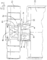
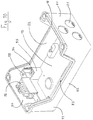
- a box 10 of molded plastic material consists of a box 11 on which is fitted in a sealed manner, a cover 12.
- the box 11 carries a rail with a symmetrical profile for latching modular electrical devices 13 , whose front face provided with a handle 14, projects from a rectangular opening 15 formed in the cover 12.
- the cover 12 is fixed to the housing 11 by four screws 16, and a seal 17 is interposed between the cover 12 and the housing 11, being housed in a peripheral groove 18 of the housing 11.
- the housing 11 has a bottom 19 to which two small side faces 20 are connected, equipped with orifices 21 for passage of the cables or wires connected to the devices 13, and two large side faces 22.
- the large side faces have a notch 23, reducing in the central part the height of these walls to facilitate the installation of cables and their connection to devices.
- similar 13 housed in the housing.
- the cover 12 is put in place, after completion of this wiring and mounting of the devices 13, on the rail with symmetrical profile.
- the cover 12 has of course a shape combined with that of the housing 11, to constitute in the fixed position a housing 10 of generally parallelepiped shape.
- a border 24 is formed in the form of a projecting frame receiving a seal, this border occupying almost the entire width of the cover 12, but leaving the side of the length, on both sides, of the free parts 25.26.
- One of the free parts 25 carries an articulation 27 of a cover or of a window 28 capable of covering, in the folded position, the opening 15.
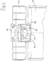
- the cover 28 of transparent plastic material, hereinafter called window is extended on the side opposite to the articulation 27 by a locking button 29, covering the free part 26 of the cover 12 in the closed position of the window 28.
- the edge opposite the articulation 27 of the window 28, bears on the outer part at the periphery of the opening 15, a fixing tab 30 having a recess in form of drawer 31 in which a conjugate part 32 of the locking button 29 fits.
- the two lateral faces of the drawer 31 are arranged in a ramp 33 having an inversion point 34 defining a narrowed passage point.
- the part 32 carries two fingers in the form of tongues 35, the ends or spouts 36 of which cooperate during the introduction of the part 32 into the recess 31, with the ramps 33.
- the central part of the part 32 is arranged in bolt 37, the end of which cooperates in the locked position with a spout 38, arranged on the edge 24 of the opening 15.
- the bolt 37 has on its rear part two flanges 39, capable of cooperating with two elastic tongues 40, formed on the bottom of the recess 31. These tabs 40 disappear when the part 32 is inserted into the drawer 31, and return elastically to the stop position, as soon as the rear edges 39 of the bolt 37 are crossed.
- These tabs 40 constitute stops limiting the return stroke in the unlocking direction of the button 29.
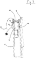
- the locking button 29 is put into place on the window 28 by fitting the part 32 into the recess 31, the end nozzles 36 cooperating at first with the converging ramps 33, of the recess 31, by folding elastically. ( Figures 3 and 4). As soon as the inversion point 34 has been crossed, the nozzles 36 cooperate with the divergent parts of the ramps 33 and urge the button 29 in the position adjoining the window 28, which corresponds to the locking position, the bolt 37 engaging under the spout 38 of the cover 12. During this positioning movement, the tongues elastic 40 are first folded to free the passage of the bolt 37, and then returned to the stop position, interfering with the path of the edges 39 of the bolt 37.
- the window 28 In the locking position of the button 29, the window 28 is held rigidly in contact with the frame 24 while sealing the opening 15.
- the window 28 is unlocked by a reverse movement of the button 29 in the direction of separation of the window 28. This movement is limited by the tabs 40 which engage the rear edges 39 of the bolt 37, this engagement intervening before the crossing point 34 is crossed by the nozzles 36.
- the elastic fingers 35 In this position represented by FIG. 6, the elastic fingers 35 always exert a restoring force in position for locking on the button 29 by their action on the divergent parts of the ramps 33.
- This elastic return action is also maintained in the locking position rep shown in FIG. 5, the spouts 36 being always in contact with the divergent parts of the ramps 33.
- This elastic mounting of the button 29 allows the window to be closed by simple folding down, the bolt 37 being pushed back by the inclined face of the spout 38, and subsequently coming to snap under this spout, to lock the window 28.
- the button 29 carries a sealing orifice 41, coming in the closed position of the window 28, opposite a conjugate orifice 42 formed on a tab 43 of the cover 12.
- the installation of a sealing wire prevents the displacement of the button 29 in the unlocking direction and secures the button 29, and therefore the window 28 with the cover 12.
- the front face of the button 29 has a housing 44, capable of receiving a lock 45 having a key not shown.
- the bolt 46 of the lock 45 engages under the edges of a notched opening 47 of the cover 12 to secure the button 29 with the cover 12. In the unlocked position of the lock 45, the bolt 46 can be separated from the cover 12 to allow the unlocking movement of the button 29.
- the cover 12 is fixed to the housing 11 by screws 16, the head 48 of which has a hole 49 for the passage of a sealing wire.
- the hole 49 directed in the axial direction of the screw 16 opens into a conduit 50 curved towards the outside and formed in the cover 12 and in extension in the housing 11. It is understood that by threading the sealing wire 51 into the head 48 , the end of this wire 51 is guided by the curved orifice 50 towards the outside, where it is easily caught and secured to the other end of the wire.
- the box 10 is inviolable.
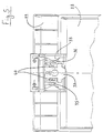
- FIG. 10 shows a device for fixing a terminal block 52 in the form of a bar, extending along one of the small side walls 20 of the housing 11.
- the terminal block 52 is snapped onto a support 53 formed by a folded flat iron, to form a frame whose base is open.
- This frame 53 is fixed by the folded tabs 54 to half columns integral with the housing 11, and coming from molding with the latter. It is easy to see that this method of fixing, for example by screws, makes it possible to free the entire width of the housing 11 for the bar 52, the flat iron 53 constituting at the same time an extension freeing the passage of cables or connection wires .
- FIG. 11 illustrates an alternative embodiment of a terminal block produced by a molded plastic part 56, arranged to constitute a frame in the shape of a stirrup which can be screwed onto the half-posts 55.
- the connection strip 52 is fixed by snap-fastening or by any other means on the support 56.
- the entire width of the housing 11 can be occupied by the terminal block 52.
- the box is made up of a limited number of molded plastic parts, the manufacturing and mounting cost being relatively low.
- the seal is ensured by the seals between the housing and the cover, and between the cover and the window.
- the window 28 is opened by simple action on the button 29, a spring possibly being able to move the window 28 to the open position.
- the arrangement of the button 29 in the extension of the window 28 overlapping the free part 26, gives a particular aesthetic to the box and avoids any dangerous protrusion.
- the position of the symmetrical profile rail is adjustable in depth and can occupy two distinct positions thanks to mounting attachments at the bottom of the housing.
- the risers are advantageously fitted as end stops for devices snapped onto the rail.
Landscapes
- Engineering & Computer Science (AREA)
- Power Engineering (AREA)
- Casings For Electric Apparatus (AREA)
- Connection Or Junction Boxes (AREA)
- Switch Cases, Indication, And Locking (AREA)
- Insertion, Bundling And Securing Of Wires For Electric Apparatuses (AREA)
Applications Claiming Priority (2)
| Application Number | Priority Date | Filing Date | Title |
|---|---|---|---|
| FR9009810A FR2665328B1 (fr) | 1990-07-30 | 1990-07-30 | Coffret etanche d'appareillage electrique. |
| FR9009810 | 1990-07-30 |
Publications (2)
| Publication Number | Publication Date |
|---|---|
| EP0470010A1 true EP0470010A1 (de) | 1992-02-05 |
| EP0470010B1 EP0470010B1 (de) | 1995-01-18 |
Family
ID=9399304
Family Applications (1)
| Application Number | Title | Priority Date | Filing Date |
|---|---|---|---|
| EP91420239A Expired - Lifetime EP0470010B1 (de) | 1990-07-30 | 1991-07-10 | Geschlossener Kasten für elektrische Apparatur |
Country Status (9)
| Country | Link |
|---|---|
| US (1) | US5157577A (de) |
| EP (1) | EP0470010B1 (de) |
| CA (1) | CA2047462A1 (de) |
| DE (1) | DE69106809T2 (de) |
| ES (2) | ES2069864T3 (de) |
| FR (1) | FR2665328B1 (de) |
| PT (1) | PT98479B (de) |
| TR (1) | TR25184A (de) |
| ZA (1) | ZA915927B (de) |
Families Citing this family (23)
| Publication number | Priority date | Publication date | Assignee | Title |
|---|---|---|---|---|
| JPH0664904B2 (ja) * | 1991-10-18 | 1994-08-22 | インターナショナル・ビジネス・マシーンズ・コーポレイション | 密封型の磁気ディスク装置 |
| DE9203533U1 (de) * | 1992-03-17 | 1993-07-15 | Klöckner-Moeller GmbH, 5300 Bonn | Deckel für die Frontseite von elektrischen Schaltgeräten mit Kipphebelbetätigung, insbesondere Niederspannungs-Leistungsschaltern |
| US5315483A (en) * | 1992-10-05 | 1994-05-24 | Motorola, Inc. | Housing having non-planar radial seal |
| US5568859A (en) * | 1995-08-08 | 1996-10-29 | Laser Industries, Limited | Foldable foot switch |
| USD385850S (en) * | 1995-09-21 | 1997-11-04 | Tii Industries Inc. | Terminal closure |
| US5825613A (en) * | 1997-03-06 | 1998-10-20 | Strongarm Designs, Inc. | Tilting display with cabinet seal |
| DE29718540U1 (de) * | 1997-10-18 | 1999-02-18 | Robert Bosch Gmbh, 70469 Stuttgart | Gehäuse mit Verriegelung |
| US6534735B1 (en) * | 2001-07-25 | 2003-03-18 | Reliance Controls Corporation | Cover assembly for a transfer switch |
| CA2538584C (en) * | 2005-05-27 | 2011-02-22 | Master Lock Company Llc | Mountable lockout device |
| ES2281293B1 (es) * | 2006-03-08 | 2008-09-01 | Simon, S.A. | Caja estanca de superficie o empotrable para mecanismos electricos. |
| US8141965B2 (en) * | 2008-06-11 | 2012-03-27 | Adc Telecommunications, Inc. | L-shaped door with three-surface seal for endplates |
| US7812254B2 (en) * | 2008-06-11 | 2010-10-12 | Adc Telecommunications, Inc. | Solar shields |
| US8031470B2 (en) * | 2008-06-11 | 2011-10-04 | Adc Telecommunications, Inc. | Systems and methods for thermal management |
| US8083302B2 (en) * | 2008-06-11 | 2011-12-27 | Adc Telecommunications, Inc. | L-shaped doors with trapezoidal seal |
| US8508917B2 (en) * | 2010-03-26 | 2013-08-13 | Egs Electrical Group, Llc | Sealed circuit breaker |
| US8559167B1 (en) * | 2010-10-04 | 2013-10-15 | Reliance Controls Corporation | Modular Housing for a transfer switch |
| USD699681S1 (en) | 2011-03-24 | 2014-02-18 | Cooper Technologies Company | Equipment for accident prevention |
| GB2489414A (en) * | 2011-03-24 | 2012-10-03 | Cooper Medc Ltd | A weatherproof cover for an alarm button |
| USD765599S1 (en) * | 2013-07-17 | 2016-09-06 | Cooper Crouse-Hinds Gmbh | Socket |
| USD750023S1 (en) * | 2014-06-20 | 2016-02-23 | Omron Corporation | Terminal block |
| CN108206463A (zh) * | 2018-02-05 | 2018-06-26 | 安徽开美电气有限公司 | 一种具有可调式分隔机构的低压开关柜 |
| FR3089699B1 (fr) * | 2018-12-06 | 2021-10-08 | Nexans | Boitier de connexion |
| NL2035412B1 (en) * | 2023-07-18 | 2025-01-30 | Ghuss Adam | Distribution board |
Citations (3)
| Publication number | Priority date | Publication date | Assignee | Title |
|---|---|---|---|---|
| FR2190328A7 (de) * | 1972-06-22 | 1974-01-25 | Bbc Brown Boveri & Cie | |
| EP0038934A2 (de) * | 1980-04-25 | 1981-11-04 | BROWN, BOVERI & CIE Aktiengesellschaft Mannheim | Installationsverteiler |
| DE8308793U1 (de) * | 1983-03-24 | 1983-06-09 | Hager Electro GmbH + Co, 6601 Ensheim | Haube für eine elektrische Installation, insbesondere vor einem Elektrizitätszähler |
Family Cites Families (5)
| Publication number | Priority date | Publication date | Assignee | Title |
|---|---|---|---|---|
| US1412242A (en) * | 1918-04-15 | 1922-04-11 | Horton Bryson Dexter | Electrical switch and interlocking casing |
| GB879669A (en) * | 1958-06-07 | 1961-10-11 | Bassani Spa | Improvements in or relating to electric switches |
| US3356907A (en) * | 1965-06-28 | 1967-12-05 | Westinghouse Electric Corp | Panelboard structure with adjustable shield |
| US4073000A (en) * | 1976-06-30 | 1978-02-07 | S & C Electric Company | Electrical interlock apparatus for electrical equipment |
| US5134543A (en) * | 1989-07-19 | 1992-07-28 | Square D Company | Electrical load center |
-
1990
- 1990-07-30 FR FR9009810A patent/FR2665328B1/fr not_active Expired - Fee Related
-
1991
- 1991-07-10 ES ES91420239T patent/ES2069864T3/es not_active Expired - Lifetime
- 1991-07-10 DE DE69106809T patent/DE69106809T2/de not_active Expired - Fee Related
- 1991-07-10 EP EP91420239A patent/EP0470010B1/de not_active Expired - Lifetime
- 1991-07-19 CA CA002047462A patent/CA2047462A1/en not_active Abandoned
- 1991-07-23 US US07/734,680 patent/US5157577A/en not_active Expired - Fee Related
- 1991-07-29 ZA ZA915927A patent/ZA915927B/xx unknown
- 1991-07-29 PT PT98479A patent/PT98479B/pt not_active IP Right Cessation
- 1991-07-30 ES ES19919102420U patent/ES1019127Y/es not_active Expired - Fee Related
- 1991-07-30 TR TR91/0746A patent/TR25184A/xx unknown
Patent Citations (3)
| Publication number | Priority date | Publication date | Assignee | Title |
|---|---|---|---|---|
| FR2190328A7 (de) * | 1972-06-22 | 1974-01-25 | Bbc Brown Boveri & Cie | |
| EP0038934A2 (de) * | 1980-04-25 | 1981-11-04 | BROWN, BOVERI & CIE Aktiengesellschaft Mannheim | Installationsverteiler |
| DE8308793U1 (de) * | 1983-03-24 | 1983-06-09 | Hager Electro GmbH + Co, 6601 Ensheim | Haube für eine elektrische Installation, insbesondere vor einem Elektrizitätszähler |
Also Published As
| Publication number | Publication date |
|---|---|
| FR2665328A1 (fr) | 1992-01-31 |
| EP0470010B1 (de) | 1995-01-18 |
| FR2665328B1 (fr) | 1992-10-09 |
| DE69106809D1 (de) | 1995-03-02 |
| US5157577A (en) | 1992-10-20 |
| ES2069864T3 (es) | 1995-05-16 |
| PT98479A (pt) | 1993-09-30 |
| ZA915927B (en) | 1992-03-25 |
| DE69106809T2 (de) | 1995-08-17 |
| ES1019127Y (es) | 1993-07-16 |
| PT98479B (pt) | 1999-01-29 |
| ES1019127U (es) | 1992-03-01 |
| TR25184A (tr) | 1992-11-01 |
| CA2047462A1 (en) | 1992-01-31 |
Similar Documents
| Publication | Publication Date | Title |
|---|---|---|
| EP0470010B1 (de) | Geschlossener Kasten für elektrische Apparatur | |
| FR2768867A1 (fr) | Systeme de confinement de fils destine a etre monte sur une structure de mur | |
| EP0392955B1 (de) | Behälter zum Unterbringen von elektrischen Apparaten | |
| FR2580860A1 (fr) | Cache-borne pour un appareil electrique basse tension a boitier isolant modulaire | |
| FR2569046A1 (fr) | Dispositif de cadenassage d'un disjoncteur miniature | |
| EP0785606B1 (de) | Vorrichtung zum Befestigen eines elektrischen Gerätes | |
| FR2771844A1 (fr) | Dispositif de traversee, notamment pour boitier d'equipement electrique | |
| FR2687248A1 (fr) | Dispositif de raccordement d'un disjoncteur basse tension a boitier moule. | |
| EP1137142B1 (de) | Einbaudose für elektrisches Gerät zur Montage entlang einem Kabelkanal | |
| EP1137897B1 (de) | Verbindungs- und schutzgehäuse für eine mast-aufsetzleuchte | |
| FR2524721A1 (fr) | Bornier de raccordement pour fils electriques | |
| FR2609354A1 (fr) | Dispositif d'encliquetage d'un capot cache-borne | |
| EP0746072A1 (de) | Gehäuse zur Aufnahme insbesondere elektrischer Geräte | |
| EP0483021B1 (de) | Verriegelbarer Deckel für elektrischen Kasten | |
| FR2622734A1 (fr) | Boitier pour appareil de coupure, notamment disjoncteur ou interrupteur, utilisable en atmosphere explosible | |
| FR2679356A1 (fr) | Tableau de comptage. | |
| FR2712165A1 (fr) | Bonde à clapet pour appareil sanitaire du genre baignoire ou autre. | |
| FR2746975A1 (fr) | Tableau electrique d'abonne | |
| BE1003141A6 (fr) | Boite sous plancher. | |
| FR2575868A1 (fr) | Cache-bornes pour appareil electrique modulaire | |
| FR2805672A1 (fr) | Embout pour goulotte de cheminement de cables ou de conducteurs electriques | |
| EP2199504B1 (de) | Verriegelungsmechanismus für Tür und Schaltschrank mit einem derartigen Verriegelungsmechanismus | |
| EP0954063A2 (de) | Verrieglungsvorrichtung für elektrischen Steckverbinder | |
| FR2644965A3 (fr) | Boite modulaire pour elements electriques | |
| KR200252128Y1 (ko) | 김치저장고의 힌지구조 |
Legal Events
| Date | Code | Title | Description |
|---|---|---|---|
| PUAI | Public reference made under article 153(3) epc to a published international application that has entered the european phase |
Free format text: ORIGINAL CODE: 0009012 |
|
| AK | Designated contracting states |
Kind code of ref document: A1 Designated state(s): BE CH DE ES GB IT LI SE |
|
| 17P | Request for examination filed |
Effective date: 19920707 |
|
| 17Q | First examination report despatched |
Effective date: 19940406 |
|
| GRAA | (expected) grant |
Free format text: ORIGINAL CODE: 0009210 |
|
| AK | Designated contracting states |
Kind code of ref document: B1 Designated state(s): BE CH DE ES GB IT LI SE |
|
| PG25 | Lapsed in a contracting state [announced via postgrant information from national office to epo] |
Ref country code: GB Effective date: 19950118 |
|
| REF | Corresponds to: |
Ref document number: 69106809 Country of ref document: DE Date of ref document: 19950302 |
|
| ITF | It: translation for a ep patent filed | ||
| PG25 | Lapsed in a contracting state [announced via postgrant information from national office to epo] |
Ref country code: SE Effective date: 19950418 |
|
| REG | Reference to a national code |
Ref country code: ES Ref legal event code: FG2A Ref document number: 2069864 Country of ref document: ES Kind code of ref document: T3 |
|
| GBV | Gb: ep patent (uk) treated as always having been void in accordance with gb section 77(7)/1977 [no translation filed] |
Effective date: 19950118 |
|
| PG25 | Lapsed in a contracting state [announced via postgrant information from national office to epo] |
Ref country code: LI Effective date: 19950731 Ref country code: CH Effective date: 19950731 Ref country code: BE Effective date: 19950731 |
|
| PLBE | No opposition filed within time limit |
Free format text: ORIGINAL CODE: 0009261 |
|
| STAA | Information on the status of an ep patent application or granted ep patent |
Free format text: STATUS: NO OPPOSITION FILED WITHIN TIME LIMIT |
|
| 26N | No opposition filed | ||
| BERE | Be: lapsed |
Owner name: MERLIN GERIN Effective date: 19950731 |
|
| REG | Reference to a national code |
Ref country code: CH Ref legal event code: PL |
|
| PGFP | Annual fee paid to national office [announced via postgrant information from national office to epo] |
Ref country code: DE Payment date: 20000706 Year of fee payment: 10 |
|
| PGFP | Annual fee paid to national office [announced via postgrant information from national office to epo] |
Ref country code: ES Payment date: 20000719 Year of fee payment: 10 |
|
| PG25 | Lapsed in a contracting state [announced via postgrant information from national office to epo] |
Ref country code: ES Free format text: LAPSE BECAUSE OF NON-PAYMENT OF DUE FEES Effective date: 20010711 |
|
| PG25 | Lapsed in a contracting state [announced via postgrant information from national office to epo] |
Ref country code: DE Free format text: LAPSE BECAUSE OF NON-PAYMENT OF DUE FEES Effective date: 20020501 |
|
| REG | Reference to a national code |
Ref country code: ES Ref legal event code: FD2A Effective date: 20020810 |
|
| PG25 | Lapsed in a contracting state [announced via postgrant information from national office to epo] |
Ref country code: IT Free format text: LAPSE BECAUSE OF NON-PAYMENT OF DUE FEES;WARNING: LAPSES OF ITALIAN PATENTS WITH EFFECTIVE DATE BEFORE 2007 MAY HAVE OCCURRED AT ANY TIME BEFORE 2007. THE CORRECT EFFECTIVE DATE MAY BE DIFFERENT FROM THE ONE RECORDED. Effective date: 20050710 |