EP0470064A2 - Moteur à combustion interne - Google Patents
Moteur à combustion interne Download PDFInfo
- Publication number
- EP0470064A2 EP0470064A2 EP19910890146 EP91890146A EP0470064A2 EP 0470064 A2 EP0470064 A2 EP 0470064A2 EP 19910890146 EP19910890146 EP 19910890146 EP 91890146 A EP91890146 A EP 91890146A EP 0470064 A2 EP0470064 A2 EP 0470064A2
- Authority
- EP
- European Patent Office
- Prior art keywords
- internal combustion
- combustion engine
- actuator
- elements
- engine according
- Prior art date
- Legal status (The legal status is an assumption and is not a legal conclusion. Google has not performed a legal analysis and makes no representation as to the accuracy of the status listed.)
- Granted
Links
- 238000002485 combustion reaction Methods 0.000 title claims abstract description 24
- 230000001105 regulatory effect Effects 0.000 claims abstract description 10
- 239000012528 membrane Substances 0.000 claims description 7
- 239000012530 fluid Substances 0.000 claims description 4
- 238000005452 bending Methods 0.000 description 5
- 230000005540 biological transmission Effects 0.000 description 3
- 238000010276 construction Methods 0.000 description 3
- 230000009466 transformation Effects 0.000 description 2
- 241001136792 Alle Species 0.000 description 1
- 238000004378 air conditioning Methods 0.000 description 1
- 230000001276 controlling effect Effects 0.000 description 1
- 230000001066 destructive effect Effects 0.000 description 1
- 238000006073 displacement reaction Methods 0.000 description 1
- 230000005520 electrodynamics Effects 0.000 description 1
- 238000005516 engineering process Methods 0.000 description 1
- 230000005284 excitation Effects 0.000 description 1
- 239000003302 ferromagnetic material Substances 0.000 description 1
- 239000000725 suspension Substances 0.000 description 1
- 238000013519 translation Methods 0.000 description 1
- 230000014616 translation Effects 0.000 description 1
Images


Classifications
-
- F—MECHANICAL ENGINEERING; LIGHTING; HEATING; WEAPONS; BLASTING
- F16—ENGINEERING ELEMENTS AND UNITS; GENERAL MEASURES FOR PRODUCING AND MAINTAINING EFFECTIVE FUNCTIONING OF MACHINES OR INSTALLATIONS; THERMAL INSULATION IN GENERAL
- F16F—SPRINGS; SHOCK-ABSORBERS; MEANS FOR DAMPING VIBRATION
- F16F15/00—Suppression of vibrations in systems; Means or arrangements for avoiding or reducing out-of-balance forces, e.g. due to motion
- F16F15/02—Suppression of vibrations of non-rotating, e.g. reciprocating systems; Suppression of vibrations of rotating systems by use of members not moving with the rotating systems
-
- B—PERFORMING OPERATIONS; TRANSPORTING
- B60—VEHICLES IN GENERAL
- B60K—ARRANGEMENT OR MOUNTING OF PROPULSION UNITS OR OF TRANSMISSIONS IN VEHICLES; ARRANGEMENT OR MOUNTING OF PLURAL DIVERSE PRIME-MOVERS IN VEHICLES; AUXILIARY DRIVES FOR VEHICLES; INSTRUMENTATION OR DASHBOARDS FOR VEHICLES; ARRANGEMENTS IN CONNECTION WITH COOLING, AIR INTAKE, GAS EXHAUST OR FUEL SUPPLY OF PROPULSION UNITS IN VEHICLES
- B60K5/00—Arrangement or mounting of internal-combustion or jet-propulsion units
-
- F—MECHANICAL ENGINEERING; LIGHTING; HEATING; WEAPONS; BLASTING
- F16—ENGINEERING ELEMENTS AND UNITS; GENERAL MEASURES FOR PRODUCING AND MAINTAINING EFFECTIVE FUNCTIONING OF MACHINES OR INSTALLATIONS; THERMAL INSULATION IN GENERAL
- F16F—SPRINGS; SHOCK-ABSORBERS; MEANS FOR DAMPING VIBRATION
- F16F15/00—Suppression of vibrations in systems; Means or arrangements for avoiding or reducing out-of-balance forces, e.g. due to motion
- F16F15/005—Suppression of vibrations in systems; Means or arrangements for avoiding or reducing out-of-balance forces, e.g. due to motion using electro- or magnetostrictive actuation means
-
- B—PERFORMING OPERATIONS; TRANSPORTING
- B60—VEHICLES IN GENERAL
- B60G—VEHICLE SUSPENSION ARRANGEMENTS
- B60G2400/00—Indexing codes relating to detected, measured or calculated conditions or factors
- B60G2400/50—Pressure
-
- B—PERFORMING OPERATIONS; TRANSPORTING
- B60—VEHICLES IN GENERAL
- B60G—VEHICLE SUSPENSION ARRANGEMENTS
- B60G2400/00—Indexing codes relating to detected, measured or calculated conditions or factors
- B60G2400/90—Other conditions or factors
- B60G2400/91—Frequency
-
- B—PERFORMING OPERATIONS; TRANSPORTING
- B60—VEHICLES IN GENERAL
- B60G—VEHICLE SUSPENSION ARRANGEMENTS
- B60G2401/00—Indexing codes relating to the type of sensors based on the principle of their operation
- B60G2401/10—Piezoelectric elements
-
- B—PERFORMING OPERATIONS; TRANSPORTING
- B60—VEHICLES IN GENERAL
- B60K—ARRANGEMENT OR MOUNTING OF PROPULSION UNITS OR OF TRANSMISSIONS IN VEHICLES; ARRANGEMENT OR MOUNTING OF PLURAL DIVERSE PRIME-MOVERS IN VEHICLES; AUXILIARY DRIVES FOR VEHICLES; INSTRUMENTATION OR DASHBOARDS FOR VEHICLES; ARRANGEMENTS IN CONNECTION WITH COOLING, AIR INTAKE, GAS EXHAUST OR FUEL SUPPLY OF PROPULSION UNITS IN VEHICLES
- B60K5/00—Arrangement or mounting of internal-combustion or jet-propulsion units
- B60K5/12—Arrangement of engine supports
- B60K5/1283—Adjustable supports, e.g. the mounting or the characteristics being adjustable
Definitions
- the invention relates to an internal combustion engine with a sound-conducting internal structure, consisting essentially of a cylinder block, cylinder head and crankshaft bearing, which is supported by means of brackets with devices for active noise reduction.
- Devices for active noise reduction have been known for a long time. Such systems are successfully used above all to reduce airborne noise in pipes and lines, e.g. in air conditioning ducts, incinerators and exhaust systems.
- the primary sound to be reduced is overlaid with the help of a loudspeaker with an equally large and 180 ° phase-diffuse "anti-sound", which counteracts the primary sound and compensates it by destructive interference.
- a signal is obtained either with a microphone or directly from the primary sound source, from which a regulating or control unit generates the signal for controlling the loudspeaker.
- the low-frequency vibrations stem from the 2nd order mass forces. They are between 20 and 200 Hz. These can be compensated with a second-order mass balance, which, however, requires a great deal of effort. In internal combustion engines without this mass balance, these vibrations, which are unpleasant for the vehicle, can be reduced with complex engine mountings or holding devices for the internal structure.
- Such mounts with devices for active noise reduction in connection with internal combustion engines have become known, for example, from DE-OS 34 19 437 on which this invention is based.
- the device referred to here as a hydraulically damped engine mount has two chambers, which are separated by an intermediate plate with a throttle point and filled with a hydraulic fluid, the motor-side chamber having an active vibration exciter (actuator) which can be controlled as a function of predefinable operating parameters.
- This vibration exciter which can operate pneumatically, hydraulically or electrodynamically, can be used to specifically generate vibrations in phase opposition to those in the holder, thereby preventing the transmission of structure-borne noise.
- the radiated airborne sound cannot be influenced with this device.
- the object of the invention is to develop an internal combustion engine of the type mentioned at the outset in such a way that the sound-conducting inner structure largely vibrates from the engine mount or is decoupled from the vehicle, wherein the radiated airborne noise should also be minimized.
- the internal combustion engine has a preferably closed, sound-absorbing outer structure, which is connected to the inner structure via at least three brackets each having a device for active noise reduction, that each device has at least one sensor element for detecting structure-borne sound vibrations and at least one Actuator element for generating antiphase structure-borne sound vibrations, a preferably electronic regulating and control device being provided, via which the actuator elements are connected to the sensor elements.
- the basic idea of such an actively noise-reduced internal combustion engine is that the force-carrying inner structure is connected to the outer structure by only a few connecting elements, so that only a few defined structure-borne sound vibration modes are permitted, the transmission of which via the holding elements acting as sound waveguides is prevented by suitable devices.
- the sound to be reduced is channeled, so to speak, so that the principle of active noise reduction can be applied to each quasi one-dimensional sound transmission channel. Airborne noise is effectively reduced by the sound-absorbing outer structure.
- each articulation point of each holder is articulated on the inner or outer structure, preferably as a ball joint, the articulation points of the holders being located at points of high mechanical rigidity (impedance) of the inner and outer structure .
- the sensor element and the actuator element each consist of at least one piezoelectric element, the electrode surfaces of which are connected via at least one control channel of the regulating and control device, or that at least two piezoelectric elements are combined via a biasing element, each piezoelectric element has at least three areas provided with electrodes and the mutually assigned areas of two piezoelectric elements are each connected via a control channel of the regulating and control device and form a pair of actuator and sensor element.
- each unit of actuator and sensor elements are arranged in a plane normal to the longitudinal axis of the holder, each sensor element and each actuator element each consisting of a piezoelectric element, and each unit has its own control channel for the regulating and control device.
- These brackets can also be used to transmit moments, whereby vibrational forces perpendicular to the longitudinal axis of the brackets are counteracted.
- devices for impedance matching of the device for reducing noise to the vibrating system may be required.
- large acoustic forces generated by piezoelectric actuators but only small displacement amplitudes.
- Suitable transformers can be used to deliver the applied power in the required ratio of sound power to sound speed.
- the sensor element and the actuator element each consist of a disk-shaped piezoelectric element, which elements are separated by a central electrode plate between two membranes, that connectable housing parts of the device for noise reduction adjoin each other, of which at least one housing part unites pressure chamber sealed off from the adjoining diaphragm for receiving a hydraulic fluid has, wherein the pressure chamber is connected to a piston chamber, the piston loaded by a spring element is connected to a strut leading to a pivot point.
- the at least one pressure chamber has a hydraulic connection, via which pressure waves which can be tapped at the internal combustion engine and are phase-shifted to vibrations caused by inertia forces can be introduced into the pressure chamber.
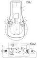
- the sound-conducting inner structure 1 of an internal combustion engine consisting essentially of a cylinder block, cylinder head and crankshaft bearing, is connected to a sound-absorbing outer structure 3 at at least three (shown two) points by means of brackets 2.
- the brackets 2 are attached to articulation points 4 both on the inner structure 1 and on the sound-absorbing outer structure 3.
- a device 5, which brings about active noise reduction, is located between the two articulation points 4.
- the articulation points 4 are located at points of high mechanical rigidity (impedance), so that only small movement amplitudes occur.
- FIG. 2 shows an example of a simple embodiment of the regulating and control electronics 8 (FIG. 1) belonging to each pair of sensor 6 and actuator 7.
- the charge signal 7 coming from the piezoelectric sensor 6 is amplified in a charge amplifier stage 9, a passive low-pass filter 10 and a power amplifier (booster) 11 and via a transformer 12 for adapting the electrical impedance to the piezoelectric actuator 7 created.
- An ohmic feedback 13 stabilizes the DC operating point and limits the effective frequency range at low frequencies. Since actuator 7 and sensor 6 are located practically at the same location, the force F N coming from the motor is ideally compensated by the force F A generated by the actuator. Forces F E not compensated are detected and processed by sensor 6.
- FIG. 3 shows the idealized frequency response of the control electronics according to FIG. 2.
- the magnitude ratio of the generated sound force F A at the actuator to the registered sound force F E at the sensor is plotted on a double logarithmic scale over the frequency F.
- This characteristic curve also represents the controller characteristic.
- the design must be such that no mechanical resonances in the frequency band of the control can be excited, i.e. the anchors and brackets must be stiff and light in relation to the stimulable structure-borne vibration modes.
- Fig. 4 shows a bracket 2, in which the articulation point 4 e.g. rigid on the inner structure 1 and the other articulation point 4 articulated on the outer structure 3, e.g. is designed as a ball joint 14, so that only the longitudinal forces and the two bending moments can be transmitted. Pairs of adjacent piezoelectric actuators 7 and sensors 6, which are each connected via a control channel 16 of the regulating and control device 8, serve as active elements. The pierzoelectric elements 15 are combined via a biasing element 17.
- each piezoelectric element 15 has four areas provided with electrodes 18, areas which are assigned to one another of two elements 15 lying one above the other each forming a pair of actuator and sensor elements and via a channel 16 of the control element. and control device 8.
- a plurality of units 19 composed of actuator and sensor elements (for example one sensor element, several actuator elements) can also be arranged in a plane 21 normal to the longitudinal axis 20 of the holder, the sensor elements 6 and actuator elements 7 consisting of separate (in FIG. 6 arranged one above the other) piezoelectric elements 15 '.
- both the sensor element 6 and the actuator element 7 each consist of a large-area piezoelectric element 15. Both elements are clamped separately between two membranes 23 by an electrode plate 22. Ar both membranes 23 connect housing parts 24 of the device 5 which can be connected to one another and which have pressure spaces 25 sealed off from the adjacent membranes for receiving a hydraulic fluid. Each pressure chamber 25 is connected to a piston chamber 26, the piston 28 of which is loaded by a spring element 27 and connected to a strut 29 leading to a pivot point is.
- the travel of the piezoelectric elements 15 is transformed up here via the ratio of the piston area to the area of the piezoelectric elements in order to achieve a sufficiently large piston stroke. It is also possible to design the device asymmetrically and to provide only one pressure chamber 25 and one piston system.
- the or both pressure chambers 25 can have a hydraulic connection 30, via which pressure waves can be introduced into the pressure chamber 25. These can, for example, be out of phase with vibrations caused by 2nd order mass forces of the internal combustion engine. This is then a controlled active element that can be implemented very efficiently in terms of energy, so that only little energy is required for the remaining noise reduction by the controlled piezoelectric element.
- FIG. 9 Another embodiment of the same principle is shown in FIG. 9, in which both pistons 28 are arranged parallel to the piezoelectric elements 15 in a space-saving manner.
Landscapes
- Engineering & Computer Science (AREA)
- General Engineering & Computer Science (AREA)
- Mechanical Engineering (AREA)
- Physics & Mathematics (AREA)
- Acoustics & Sound (AREA)
- Aviation & Aerospace Engineering (AREA)
- Transportation (AREA)
- Combustion & Propulsion (AREA)
- Chemical & Material Sciences (AREA)
- Soundproofing, Sound Blocking, And Sound Damping (AREA)
- Combined Devices Of Dampers And Springs (AREA)
- Vibration Prevention Devices (AREA)
- Arrangement Or Mounting Of Propulsion Units For Vehicles (AREA)
- Valve Device For Special Equipments (AREA)
- Valve-Gear Or Valve Arrangements (AREA)
- Exhaust Silencers (AREA)
- Measurement Of Mechanical Vibrations Or Ultrasonic Waves (AREA)
- Transition And Organic Metals Composition Catalysts For Addition Polymerization (AREA)
Applications Claiming Priority (2)
| Application Number | Priority Date | Filing Date | Title |
|---|---|---|---|
| AT161090 | 1990-07-31 | ||
| AT1610/90 | 1990-07-31 |
Publications (3)
| Publication Number | Publication Date |
|---|---|
| EP0470064A2 true EP0470064A2 (fr) | 1992-02-05 |
| EP0470064A3 EP0470064A3 (en) | 1993-04-21 |
| EP0470064B1 EP0470064B1 (fr) | 1994-12-07 |
Family
ID=3517153
Family Applications (1)
| Application Number | Title | Priority Date | Filing Date |
|---|---|---|---|
| EP91890146A Expired - Lifetime EP0470064B1 (fr) | 1990-07-31 | 1991-07-09 | Moteur à combustion interne |
Country Status (4)
| Country | Link |
|---|---|
| EP (1) | EP0470064B1 (fr) |
| JP (1) | JP2587153B2 (fr) |
| AT (1) | ATE115067T1 (fr) |
| DE (1) | DE59103765D1 (fr) |
Cited By (10)
| Publication number | Priority date | Publication date | Assignee | Title |
|---|---|---|---|---|
| DE19710965C1 (de) * | 1997-03-17 | 1998-09-10 | Univ Magdeburg Tech | Vorrichtung zur Reduzierung von Schwingungen in Zugmittelantrieben, vorzugsweise für die Handhabungstechnik |
| GB2343494A (en) * | 1998-11-04 | 2000-05-10 | Marconi Electronic Syst Ltd | Active vibration control |
| WO2000032958A2 (fr) | 1998-12-01 | 2000-06-08 | Lucas Industries Public Limited Company | Dispositif comprenant un composant aux vibrations amorties, notamment un frein |
| AT3351U3 (de) * | 1999-10-18 | 2000-09-25 | Avl List Gmbh | Hubkolbenmaschine |
| DE10110822A1 (de) * | 2001-03-07 | 2002-09-26 | Daimler Chrysler Ag | Verfahren und Vorrichtung zur Beeinflussung der Übertragung von Schwingungen eines Schwingungserzeugers an einen damit verbundenen Gegenstand, insbesondere von Motorschwingungen auf die Karosserie eines Kraftfahrzeuges |
| EP1291551A1 (fr) * | 2001-09-11 | 2003-03-12 | BorgWarner Inc. | Système de contrôle de vibrations utilisant une action piezoéléctrique |
| DE10255009A1 (de) * | 2002-11-25 | 2004-06-03 | Rolls-Royce Deutschland Ltd & Co Kg | Schwingungsdämpfungsvorrichtung sowie Verfahren zur Schwingungsdämpfung zur aktiven Dämpfung von Schwingungen eines Bauteils |
| EP1296126A3 (fr) * | 2001-09-19 | 2004-09-29 | Ford Global Technologies, Inc., A subsidiary of Ford Motor Company | Procédé de détermination de la proportion de bruit transmis par l'air ou par les solides dans le bruit moteur |
| US8037981B1 (en) | 2001-11-06 | 2011-10-18 | Eads Deutschland Gmbh | Device and process for oscillation insulation in a transmission path |
| US9669676B2 (en) | 2013-09-25 | 2017-06-06 | Audi Ag | Method for operating an electromagnetic actuator in a motor vehicle |
Families Citing this family (2)
| Publication number | Priority date | Publication date | Assignee | Title |
|---|---|---|---|---|
| DE19642827B4 (de) * | 1996-03-29 | 2005-06-23 | Zf Sachs Ag | Aktuator zur Schwingungsbedämpfung |
| DE102005043429A1 (de) | 2005-05-19 | 2006-11-23 | Fraunhofer-Gesellschaft zur Förderung der angewandten Forschung e.V. | Vorrichtung zur Schwingungsentkopplung |
Family Cites Families (7)
| Publication number | Priority date | Publication date | Assignee | Title |
|---|---|---|---|---|
| AT377331B (de) * | 1977-11-23 | 1985-03-11 | List Hans | Geraeuschgedaemmte brennkraftmaschine |
| US4531484A (en) * | 1981-11-20 | 1985-07-30 | Nissan Motor Co., Ltd. | Vibration responsive mounting arrangement for automotive engine or the like |
| JPS5986307A (ja) * | 1982-11-09 | 1984-05-18 | Shimada Phys & Chem Ind Co Ltd | エバネセントモ−ド形共振器 |
| JPS6163072A (ja) * | 1984-09-04 | 1986-04-01 | Komatsu Ltd | ガスレ−ザ |
| DE3821368A1 (de) * | 1988-06-24 | 1989-12-28 | Audi Ag | Schwingungsdaempfende und schwingungskompensierende lageranordnung |
| GB2222657B (en) * | 1988-09-09 | 1992-10-07 | Topexpress Ltd | Active control of vibration |
| DE3901737A1 (de) * | 1989-01-21 | 1990-07-26 | Phoenix Ag | Metall-gummi-lager |
-
1991
- 1991-07-09 AT AT91890146T patent/ATE115067T1/de not_active IP Right Cessation
- 1991-07-09 DE DE59103765T patent/DE59103765D1/de not_active Expired - Fee Related
- 1991-07-09 EP EP91890146A patent/EP0470064B1/fr not_active Expired - Lifetime
- 1991-07-30 JP JP3190316A patent/JP2587153B2/ja not_active Expired - Fee Related
Cited By (15)
| Publication number | Priority date | Publication date | Assignee | Title |
|---|---|---|---|---|
| DE19710965C1 (de) * | 1997-03-17 | 1998-09-10 | Univ Magdeburg Tech | Vorrichtung zur Reduzierung von Schwingungen in Zugmittelantrieben, vorzugsweise für die Handhabungstechnik |
| GB2343494B (en) * | 1998-11-04 | 2000-12-20 | Marconi Electronic Syst Ltd | Active vibration control |
| GB2343494A (en) * | 1998-11-04 | 2000-05-10 | Marconi Electronic Syst Ltd | Active vibration control |
| US6742632B2 (en) | 1998-12-01 | 2004-06-01 | Lucas Industries Plc | Apparatus with vibration-damped component, especially a brake |
| DE19855467A1 (de) * | 1998-12-01 | 2000-06-08 | Lucas Ind Plc | Vorrichtung mit schwingungsgedämpftem Bauteil, insbesondere eine Bremse |
| WO2000032958A2 (fr) | 1998-12-01 | 2000-06-08 | Lucas Industries Public Limited Company | Dispositif comprenant un composant aux vibrations amorties, notamment un frein |
| AT3351U3 (de) * | 1999-10-18 | 2000-09-25 | Avl List Gmbh | Hubkolbenmaschine |
| DE10110822A1 (de) * | 2001-03-07 | 2002-09-26 | Daimler Chrysler Ag | Verfahren und Vorrichtung zur Beeinflussung der Übertragung von Schwingungen eines Schwingungserzeugers an einen damit verbundenen Gegenstand, insbesondere von Motorschwingungen auf die Karosserie eines Kraftfahrzeuges |
| US6672434B2 (en) | 2001-03-07 | 2004-01-06 | Daimlerchrysler Ag | Method and device for influencing the transfer of vibrations of a vibration generator to an object connected to it, in particular of engine vibrations to the body of a motor vehicle |
| DE10110822B4 (de) * | 2001-03-07 | 2006-06-01 | Daimlerchrysler Ag | Verfahren und Vorrichtung zur Beeinflussung der Übertragung von Schwingungen eines Schwingungserzeugers an einen damit verbundenen Gegenstand, insbesondere von Motorschwingungen auf die Karosserie eines Kraftfahrzeuges |
| EP1291551A1 (fr) * | 2001-09-11 | 2003-03-12 | BorgWarner Inc. | Système de contrôle de vibrations utilisant une action piezoéléctrique |
| EP1296126A3 (fr) * | 2001-09-19 | 2004-09-29 | Ford Global Technologies, Inc., A subsidiary of Ford Motor Company | Procédé de détermination de la proportion de bruit transmis par l'air ou par les solides dans le bruit moteur |
| US8037981B1 (en) | 2001-11-06 | 2011-10-18 | Eads Deutschland Gmbh | Device and process for oscillation insulation in a transmission path |
| DE10255009A1 (de) * | 2002-11-25 | 2004-06-03 | Rolls-Royce Deutschland Ltd & Co Kg | Schwingungsdämpfungsvorrichtung sowie Verfahren zur Schwingungsdämpfung zur aktiven Dämpfung von Schwingungen eines Bauteils |
| US9669676B2 (en) | 2013-09-25 | 2017-06-06 | Audi Ag | Method for operating an electromagnetic actuator in a motor vehicle |
Also Published As
| Publication number | Publication date |
|---|---|
| DE59103765D1 (de) | 1995-01-19 |
| EP0470064B1 (fr) | 1994-12-07 |
| JPH0672158A (ja) | 1994-03-15 |
| ATE115067T1 (de) | 1994-12-15 |
| EP0470064A3 (en) | 1993-04-21 |
| JP2587153B2 (ja) | 1997-03-05 |
Similar Documents
| Publication | Publication Date | Title |
|---|---|---|
| EP1646805B1 (fr) | Interface modulaire servant a amortir des vibrations mecaniques | |
| DE69408015T2 (de) | Einrichtung zur Regelung von aktiven Lagern | |
| DE4116270C2 (de) | Dämpfungseinrichtung | |
| US4940914A (en) | Vibration absorbing apparatus | |
| EP0470064B1 (fr) | Moteur à combustion interne | |
| DE3888849T2 (de) | Schwingungsdämpfendes maschinenlager. | |
| DE19648986C1 (de) | Gerichteter Stabstrahler | |
| WO2008034789A1 (fr) | agencement doté d'un système de réduction active du bruit | |
| EP0964387A2 (fr) | Procédé et dispositif pour modifier la bruit générée par une vitre | |
| EP2615325A1 (fr) | Palier actif | |
| EP0347666A2 (fr) | Agencement de support pour amortir et compenser les oscillations | |
| DE60210715T2 (de) | Piezoelektrische Elemente benutzendes Schwingungsregelungssystem | |
| DE19921115C2 (de) | Fluiddichte Schwingungsabsorptionsvorrichtung | |
| EP0964386B1 (fr) | Procédé et dispositif pour modifier la conduction possible du son et éventuellement la génération du bruit d'objets | |
| EP1735542A1 (fr) | Interface a dissipation des forces de cisaillement, destinee a amortir les vibrations mecaniques | |
| DE102019202077A1 (de) | Wärmepumpe | |
| DE102019131712B4 (de) | Frequenzauslöschung verwendende geräuschreduzierungsvibrationsschweissmaschine | |
| DE3902603C2 (de) | Elastische Lagerung, insbesondere Kraftfahrzeug-Motorlager | |
| DE602005005125T2 (de) | Linearantrieb für ein Vibrationsgerät | |
| EP1959158B1 (fr) | Procédé destiné à l'adaptation d'un système d'isolation des vibrations | |
| DE3834853C2 (de) | Anordnung zur Verminderung des Geräuschpegels im Innenraum eines Kraftfahrzeugs | |
| WO2006086950A1 (fr) | Dispositif de couplage sonore entre une conduite d'admission et / ou un compartiment-moteur et l'habitacle d'un vehicule a moteur | |
| EP1432595A1 (fr) | Tete de transducteur acoustique, transducteur acoustique pourvu de cette tete et procede de transduction acoustique, en particulier pour un vehicule automobile | |
| DE3316177A1 (de) | Vorrichtung zum tilgen mechanischer schwingungen an einem maschinenbauteil insbesondere eines kraftfahrzeuges | |
| DE19826177A1 (de) | Verfahren und Vorrichtung zur Beeinflussung von Schwingungen, die von einem zumindest mittelbar motorisch angetriebenen Fahrzeug ausgehen |
Legal Events
| Date | Code | Title | Description |
|---|---|---|---|
| PUAI | Public reference made under article 153(3) epc to a published international application that has entered the european phase |
Free format text: ORIGINAL CODE: 0009012 |
|
| AK | Designated contracting states |
Kind code of ref document: A2 Designated state(s): AT DE FR GB IT SE |
|
| ITCL | It: translation for ep claims filed |
Representative=s name: MODIANO & ASSOCIATI S.R.L. |
|
| GBC | Gb: translation of claims filed (gb section 78(7)/1977) | ||
| EL | Fr: translation of claims filed | ||
| RIN1 | Information on inventor provided before grant (corrected) |
Inventor name: HARMS, KLAUS-CHRISTOPH, DR. Inventor name: MELDE-TUCZAI, DIPL.-ING. Inventor name: SKATSCHE, OTHMAR, DIPL.-ING. Inventor name: BRANDL, FRANZ, DIPL.-ING.DR.TECHN. Inventor name: CICOCKI, RAINER, DIPL.-ING. |
|
| PUAL | Search report despatched |
Free format text: ORIGINAL CODE: 0009013 |
|
| AK | Designated contracting states |
Kind code of ref document: A3 Designated state(s): AT DE FR GB IT SE |
|
| 17P | Request for examination filed |
Effective date: 19930602 |
|
| 17Q | First examination report despatched |
Effective date: 19930707 |
|
| GRAA | (expected) grant |
Free format text: ORIGINAL CODE: 0009210 |
|
| AK | Designated contracting states |
Kind code of ref document: B1 Designated state(s): AT DE FR GB IT SE |
|
| REF | Corresponds to: |
Ref document number: 115067 Country of ref document: AT Date of ref document: 19941215 Kind code of ref document: T |
|
| REF | Corresponds to: |
Ref document number: 59103765 Country of ref document: DE Date of ref document: 19950119 |
|
| GBT | Gb: translation of ep patent filed (gb section 77(6)(a)/1977) |
Effective date: 19950111 |
|
| ET | Fr: translation filed | ||
| ITF | It: translation for a ep patent filed | ||
| PG25 | Lapsed in a contracting state [announced via postgrant information from national office to epo] |
Ref country code: GB Effective date: 19950709 |
|
| PG25 | Lapsed in a contracting state [announced via postgrant information from national office to epo] |
Ref country code: SE Effective date: 19950710 |
|
| PGFP | Annual fee paid to national office [announced via postgrant information from national office to epo] |
Ref country code: AT Payment date: 19950718 Year of fee payment: 5 |
|
| PLBE | No opposition filed within time limit |
Free format text: ORIGINAL CODE: 0009261 |
|
| STAA | Information on the status of an ep patent application or granted ep patent |
Free format text: STATUS: NO OPPOSITION FILED WITHIN TIME LIMIT |
|
| 26N | No opposition filed | ||
| GBPC | Gb: european patent ceased through non-payment of renewal fee |
Effective date: 19950709 |
|
| EUG | Se: european patent has lapsed |
Ref document number: 91890146.3 |
|
| PG25 | Lapsed in a contracting state [announced via postgrant information from national office to epo] |
Ref country code: FR Effective date: 19960430 |
|
| REG | Reference to a national code |
Ref country code: FR Ref legal event code: ST |
|
| REG | Reference to a national code |
Ref country code: FR Ref legal event code: ST |
|
| REG | Reference to a national code |
Ref country code: FR Ref legal event code: ST |
|
| PG25 | Lapsed in a contracting state [announced via postgrant information from national office to epo] |
Ref country code: AT Effective date: 19960709 |
|
| PGFP | Annual fee paid to national office [announced via postgrant information from national office to epo] |
Ref country code: DE Payment date: 19970725 Year of fee payment: 7 |
|
| PG25 | Lapsed in a contracting state [announced via postgrant information from national office to epo] |
Ref country code: DE Free format text: LAPSE BECAUSE OF NON-PAYMENT OF DUE FEES Effective date: 19990501 |
|
| PG25 | Lapsed in a contracting state [announced via postgrant information from national office to epo] |
Ref country code: IT Free format text: LAPSE BECAUSE OF NON-PAYMENT OF DUE FEES;WARNING: LAPSES OF ITALIAN PATENTS WITH EFFECTIVE DATE BEFORE 2007 MAY HAVE OCCURRED AT ANY TIME BEFORE 2007. THE CORRECT EFFECTIVE DATE MAY BE DIFFERENT FROM THE ONE RECORDED. Effective date: 20050709 |