EP0470320A1 - Mechanismus zum Ausführen des stationären Betriebszustands und der Fehlerbeseitungsfunktionen eines Kommunikationsprotokolls - Google Patents
Mechanismus zum Ausführen des stationären Betriebszustands und der Fehlerbeseitungsfunktionen eines Kommunikationsprotokolls Download PDFInfo
- Publication number
- EP0470320A1 EP0470320A1 EP90480114A EP90480114A EP0470320A1 EP 0470320 A1 EP0470320 A1 EP 0470320A1 EP 90480114 A EP90480114 A EP 90480114A EP 90480114 A EP90480114 A EP 90480114A EP 0470320 A1 EP0470320 A1 EP 0470320A1
- Authority
- EP
- European Patent Office
- Prior art keywords
- message
- module
- messages
- indicators
- value
- Prior art date
- Legal status (The legal status is an assumption and is not a legal conclusion. Google has not performed a legal analysis and makes no representation as to the accuracy of the status listed.)
- Granted
Links
- 238000004891 communication Methods 0.000 title claims abstract description 58
- 230000006870 function Effects 0.000 title claims abstract description 47
- 230000007246 mechanism Effects 0.000 title claims abstract description 30
- 238000011084 recovery Methods 0.000 title claims abstract description 20
- 238000012546 transfer Methods 0.000 claims abstract description 58
- 230000005540 biological transmission Effects 0.000 claims abstract description 39
- 238000000034 method Methods 0.000 claims abstract description 36
- 230000008569 process Effects 0.000 claims description 22
- 238000012545 processing Methods 0.000 claims description 20
- 230000011664 signaling Effects 0.000 claims description 14
- 230000004044 response Effects 0.000 claims description 9
- 239000000872 buffer Substances 0.000 description 26
- 101000581533 Homo sapiens Methylcrotonoyl-CoA carboxylase beta chain, mitochondrial Proteins 0.000 description 25
- 102100027320 Methylcrotonoyl-CoA carboxylase beta chain, mitochondrial Human genes 0.000 description 25
- 238000010586 diagram Methods 0.000 description 10
- 238000012163 sequencing technique Methods 0.000 description 8
- IPQLEWIXZJLSDV-UHFFFAOYSA-N BCCB Chemical compound BCCB IPQLEWIXZJLSDV-UHFFFAOYSA-N 0.000 description 4
- 101100302211 Arabidopsis thaliana RNR2A gene Proteins 0.000 description 3
- 101001109698 Homo sapiens Nuclear receptor subfamily 4 group A member 2 Proteins 0.000 description 3
- 102100022676 Nuclear receptor subfamily 4 group A member 2 Human genes 0.000 description 3
- 101150002896 RNR2 gene Proteins 0.000 description 3
- 238000001514 detection method Methods 0.000 description 3
- 230000003213 activating effect Effects 0.000 description 2
- 238000012217 deletion Methods 0.000 description 2
- 230000037430 deletion Effects 0.000 description 2
- 238000003780 insertion Methods 0.000 description 2
- 230000037431 insertion Effects 0.000 description 2
- 238000012360 testing method Methods 0.000 description 2
- 230000008859 change Effects 0.000 description 1
- 230000001360 synchronised effect Effects 0.000 description 1
Images









Classifications
-
- H—ELECTRICITY
- H04—ELECTRIC COMMUNICATION TECHNIQUE
- H04L—TRANSMISSION OF DIGITAL INFORMATION, e.g. TELEGRAPHIC COMMUNICATION
- H04L1/00—Arrangements for detecting or preventing errors in the information received
- H04L1/12—Arrangements for detecting or preventing errors in the information received by using return channel
- H04L1/16—Arrangements for detecting or preventing errors in the information received by using return channel in which the return channel carries supervisory signals, e.g. repetition request signals
- H04L1/18—Automatic repetition systems, e.g. Van Duuren systems
- H04L1/1867—Arrangements specially adapted for the transmitter end
- H04L1/1874—Buffer management
-
- H—ELECTRICITY
- H04—ELECTRIC COMMUNICATION TECHNIQUE
- H04L—TRANSMISSION OF DIGITAL INFORMATION, e.g. TELEGRAPHIC COMMUNICATION
- H04L1/00—Arrangements for detecting or preventing errors in the information received
- H04L1/12—Arrangements for detecting or preventing errors in the information received by using return channel
- H04L1/16—Arrangements for detecting or preventing errors in the information received by using return channel in which the return channel carries supervisory signals, e.g. repetition request signals
- H04L1/1607—Details of the supervisory signal
- H04L1/1635—Cumulative acknowledgement, i.e. the acknowledgement message applying to all previous messages
-
- H—ELECTRICITY
- H04—ELECTRIC COMMUNICATION TECHNIQUE
- H04L—TRANSMISSION OF DIGITAL INFORMATION, e.g. TELEGRAPHIC COMMUNICATION
- H04L9/00—Cryptographic mechanisms or cryptographic arrangements for secret or secure communications; Network security protocols
- H04L9/40—Network security protocols
Definitions
- the communication modules can be connected to different types of local users in order to make the communication node able to perform any type of message transfers.
- modules can be connected to a host system through a communication controller of the IBM 3745 type, other modules can be connected to terminals through separate communication lines or through a serial link, other modules can be connected to local area networks, etc.
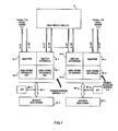
- Each module comprises a link adapter 6 to which the user links 2 are attached, a switch interface to which the switch links 4 are attached.
- link inbound queues LIQ there are as many link inbound queues LIQ as there are users attached to adapter 6 and communication modules 1-1 to 1-n.
- the link inbound queues assigned to users connected to adapters 6 are referenced LIQ-U with a suffix which indicates the module and the user number. Assuming that p users are attached to adapter 6-1 and q users are attached to adapter 6-n, the queue referenced LlQ-U1-p is assigned to the user numbered p connected to adapter 6-1 and the queue referenced LIQ-Un-q is assigned to user numbered q connected to adapter 6-n.
- the link inbound queue assigned to the communication modules 1-1 to 1-n are referenced LIQ-M with a suffix which indicates the module numbers 1-1 to 1-n.
- the messages which have to be transmitted to transmit links 2;T and 4;T are dequeued under control of the data store interfaces 12 and 14 from the LOQ queues and processed by the adapter 6 and switch interface 8 to be sent on the transmit links, as described in the above referenced patent application.
- the message is dequeued from LOQ-M1-n by the data store interface 14 as shown by path 38 and provided by the switch interface 8-1 to link 4-1;T and by high speed switch 3 to destination module 1-n through link 4-n;R.
- a shared data store 10 the various queues are identified by pointers in queue control blocks QCB. These QCB blocks contain the address of the queue head and the queue tail, so that the enqueueing operation of a message from a first queue to a second queue only requires an updating of the queue head of the first queue and of the queue tail of the second queue in the queue control blocks of the first and second queues, respectively.
- a data store interface which allows these operations to be performed in an efficient way is described in the above referenced European Patent Application 0365731.
- the data transfers through the high speed switch are performed at a speed which can reach 16 Megabytes per second in order to allow all the transfers between the end users to be carried out.
- the unnumbered frame U does not contain the NR indication in the control field. This allows additional controls.
- each communication module comprises for each possible destination communication module:
- a control block (MCCB) for each message is used for additional communications between the hardware and the microcode on a message basis.
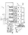
- Figure 3 represents the block diagram of the data store interface 14 which manages the transfers of messages received from link 4-R from the high speed switch 3 through the switch interface 8 and of the messages to be transmitted from link 4-T through the switch interface 8. Such a mechanism is not required in the data store interfaces 12, since the messages are transferred between links 4 and 2 through the shared memory 10.
- Data store interface DSI 6 comprises a station service arrangement SSV 50 which includes five finite state machines 50-1 to 50-5 referenced RCV, RLS, XMIT, EOM, TO.
- Data movement circuit 52 comprises a receive part 52-R and a transmit part 52-T which receives data bursts from the high speed switch 3 through data bus 54 and provides data bursts to the high speed switch 3 through data bus 56, under control of signals on control bus 58 and 60.
- the receive part 52-R performs the buffer and message chaining and the message enqueueing in the data store 10 and the transmit part 52-T performs the buffer and message unchaining and the message dequeueing from the data store 10.
- control bus 4-C is provided between the switch 8 to carry signals which are needed for controlling the data bursts transfers on data bus 4-R and 4-T.
- a configuration table 62 comprises at least n entries with one entry per communication module.
- a scheduler 64 scans the configuration table 62 to obtain an entry in a request table 66.
- the configuration table 62 can be in the same RAM memory as the request table 66.
- the request table 66 holds the set of indicators relative to each communication module. It contains a set of indicators representative of the receive RCV, release RLS, transmit XMIT, end of message EOM and time out TO conditions indicating the operations which have to be performed for each, communication module and of ERROR conditions ERR which will be detailed later on.
- the request table is updated by a table update circuit 67 as a function of the operations which are performed for each communication module as will be described later on, by the end of message signal from bus 58 and by a clock 74.
- the conditions which are read from the request table 66 are provided to scheduler 64 through bus 68 which determines the operations which have to be performed, if any. It activates a station control block feeder 70 to get the station control block SCB for the scheduled communication module from the data store 10.
- the station control block is provided to the station service arrangement 50 and the scheduler 64 activates the appropriate parts 50-1 to 50-5 of the station service arrangement 50 through bus 72 in order the station service arrangement performs the operations specified by the conditions read from the request table.
- the station control block updated by the station service is put back in data store 10.
- the MCCB and BCCB contain parameter and status information. Only a part of the MCCB contents is used for implementing the present invention.
- the indicators for one communication module contained in the request table RT 66 are shown in Figure 4.
- the ERROR bits LR and L define two error status called FROZEN and LOCK status according to the following encoding:
- the LIQ bits indicates whether the LIQ queue is empty or contains at least one message which can be dequeued.
- the LOQ bit and LOR bit indicate whether the LOQ-M1-j and LOR-M1-j are empty or not.
- the EOM conditions are indicated by a EOM counter which is incremented by the end of Message signals signalling the end of a correct transmission of one message from the queue LOQ-M1-j.
- EOM bits 0 means that no message is waiting the EOM process.
- EOM bits 1 means that one message is waiting the EOM process.
- NS/NR bit which is set at initialization by the microprocessor for indicating whether the NS/NR checking of the DLC protocol for the corresponding module is to be made by the station service hardware according to the teaching of the present invention or not.
- VR bits indicate the sequence number of the next I message expected by module 1-i from the module 1-j.
- VS bits indicate the sequence number of the next I message to transmit from module 1-i to module 1-j.
- LNR bits indicate the last NR received from module 1-j.
- TIM is a timer value.
- TS indicates that the timer is started.
- W is a transmission window value which indicates the number of messages waiting for acknowledgement in the queue LOS M1-j. This number must be lower than a maximum value Wmax.
- LOS F indicates that the LOS M1-j contains at least one message.
- MSG ADD comprises the address of the last message transmitted by module 1-i to module 1-j, i.e the address of the first buffer of the message.
- the station control block can comprise other information for any other purposes.
- NS and NR bits comprises the NS and NR sequence values for the message.
- the frame type and NR, NS bits represent the command field C of the frame.
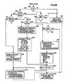
- the station service arrangement 50 is comprised of five finite state machines RCV-SSV, RLS-SSV, XMIT-SSV, EOM-SSV and TO-SSV 50-1 to 50-5 which comprise logic circuits which can be easily implemented by the man skilled in the art from the state diagrams shown in Figures 6 to 10 respectively.
- the scheduler 64 comprises a scanning clock 90 which provides an address to the configuration table CT 62 at each scanning period t1 to tn through the address bus 92-A.
- the configuration table 62 is read and the module identification read from the addressed location is provided to the SCB feeder 70 through bus 92-1.
- the module identification is provided to the SCB feeder 70 through bus 92-1 and SCB feeder generates the corresponding SCB address in data store 10.
- the SCB block read from data store 10 is written into SCB register 100.
- the SCB register contents which has been updated during the previous scanning period is written back into the memory 10 and the new SCB block for the new module is loaded into the SCB register 100. If there is no module identification change, the updated SCB register contents remains in SCB register 100 and is used by the station service arrangement during the new scanning period.
- the RT contents read from the request table 66 is saved in register 102 and provided through bus 103 to scheduling device 94 and to station service arrangement 50.
- Scheduling device is responsive to the bit configurations in the register 102 to sequentially activate the five parts of the station service 50 in the following order:
- each part of the station service When each part of the station service has completed its process, it returns a COMPLETE signal on line 114, 116, 118, 120 or 122 to the scheduling device 94 in order it activates the next part.
- the SCB register contents is provided to the five parts of the station service 50, in order to control their operations as described in reference to Figures 6 to 10.
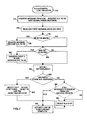
- the ACT RCV line 104 is activated (operation 120) when the LlQ-M1-j in module 1-i is not empty, which is indicated by the LIQ bit in register 102.
- This operation starts the receive process.
- the head message in the LlQ-M1-j is dequeued (operation 122).
- the address of the message to be dequeued is found in the queue control block QCB in the LIQ head field, a DEQUEUE global order is sent to centralized control circuit 22, the dequeue operation is performed.
- the address of the message which is provided in the DEQUEUE global order response is saved.
- the MCCB block of the message is read and its contents is saved (operation 124).
- the F bit in the saved message control block MCCB and the L and LR bits in the RT register 102 are tested (operation 126). If the F bit is set to 1 or if the L and LR bits are set to 1 (FROZEN STATUS), the message is flushed (released) and the message buffers are released to the free buffer queue (operation 128) through a RELEASE global order sent to centralized control circuit 22. Then, the Receive Complete line 114 is activated (operation 129).
- the NR/NS bit in the SCB in register 100 is tested (operation 130). If it is off, which means that the DLC protocol has not to be performed by the station service, the message is enqueued to the MIQ queue or to a LOQ, according to the MCCB routing information circuit by sending an ENQUEUE global order to the centralized control 22. Then, the Receive Complete line 114 is activated (operation 129).
- the P/F bit is tested (operation 134). This bit which is a bit of the control field in the frame is set to 0, in the I frames or RR frames to indicate that the DLC protocol is to be performed by the station service arrangement 50.
- the message is enqueued by sending an ENQUEUED global order to centralized control circuit 22 and line 114 is activated (operations 132 and 129).
- the frame type in MCCB is checked. It is first checked whether the message is a I message, (operation 136). If no, it is checked whether it is a RR message (operation 138). If the message is neither a I message nor a RR message it is enqueued to the MIQ queue or to a LOQ, according to the MCCB routing information (operation 132).
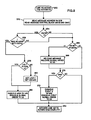
- the NR value of the I or RR received message is tested as shown in Figure 6B.
- the NR checking is performed by the same operations for the I message with no NS sequencing error (leg 143 in Figure 6-A) and for the I message with a NS sequencing error or a RR message (leg 145 in Figure 6-A). These operations are referenced by even numbers and odd numbers respectively in Figure 6-B.
- the first operations (150 and 151) consist in checking the NR value. To be good, this value must be lower or equal to VS and higher or equal to LNR. NR not valid is indicative of a DLC error.
- LNR is updated i.e set to NR (operations 154 and 155).
- this message acknowledges messages in the LOS queue LOS-M1-j (operations 156 and 157), in order to release the so-acknowledged messages.
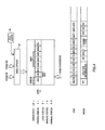
- This operation consists in testing the LOS F bit in SCB register 100 and testing whether NR is lower than or equal to the NS value of the tail message NST in the LOS queue and higher or equal to NSH + 1, assuming the messages are enqueued and chained in the LOS queue from the queue head, as described in the above referenced European patent application, and as schematically represented in Figure 6-B.
- the NS value of the head message MSG 1 is equal to 1
- NR is equal to 1, meaning that the next expected message is message 1, message 1 cannot be released since it is not acknowledged.
- NR is equal to 2
- message 1 can be released, etc..
- NR messages 1, 2, 3 can be released.
- the NST value is calculated from NSH and W, and is equal to NSH + W-1 where W in SCB register 100 is the number of messages in the LOS queue.
- Operation 159 ends the receiving process of a RR message with a NR valid, so that operation 162 is performed after operations 157 and 159.
Landscapes
- Engineering & Computer Science (AREA)
- Computer Networks & Wireless Communication (AREA)
- Signal Processing (AREA)
- Computer Security & Cryptography (AREA)
- Communication Control (AREA)
- Computer And Data Communications (AREA)
- Data Exchanges In Wide-Area Networks (AREA)
Priority Applications (3)
| Application Number | Priority Date | Filing Date | Title |
|---|---|---|---|
| DE69016018T DE69016018T2 (de) | 1990-08-10 | 1990-08-10 | Mechanismus zum Ausführen des stationären Betriebszustands und der Fehlerbeseitungsfunktionen eines Kommunikationsprotokolls. |
| EP90480114A EP0470320B1 (de) | 1990-08-10 | 1990-08-10 | Mechanismus zum Ausführen des stationären Betriebszustands und der Fehlerbeseitungsfunktionen eines Kommunikationsprotokolls |
| JP3195894A JPH0652513B2 (ja) | 1990-08-10 | 1991-07-10 | インタフエース機構 |
Applications Claiming Priority (1)
| Application Number | Priority Date | Filing Date | Title |
|---|---|---|---|
| EP90480114A EP0470320B1 (de) | 1990-08-10 | 1990-08-10 | Mechanismus zum Ausführen des stationären Betriebszustands und der Fehlerbeseitungsfunktionen eines Kommunikationsprotokolls |
Publications (2)
| Publication Number | Publication Date |
|---|---|
| EP0470320A1 true EP0470320A1 (de) | 1992-02-12 |
| EP0470320B1 EP0470320B1 (de) | 1995-01-11 |
Family
ID=8205839
Family Applications (1)
| Application Number | Title | Priority Date | Filing Date |
|---|---|---|---|
| EP90480114A Expired - Lifetime EP0470320B1 (de) | 1990-08-10 | 1990-08-10 | Mechanismus zum Ausführen des stationären Betriebszustands und der Fehlerbeseitungsfunktionen eines Kommunikationsprotokolls |
Country Status (3)
| Country | Link |
|---|---|
| EP (1) | EP0470320B1 (de) |
| JP (1) | JPH0652513B2 (de) |
| DE (1) | DE69016018T2 (de) |
Cited By (1)
| Publication number | Priority date | Publication date | Assignee | Title |
|---|---|---|---|---|
| CN112003792A (zh) * | 2020-07-23 | 2020-11-27 | 烽火通信科技股份有限公司 | 一种软硬件协同的报文加速方法和装置 |
Citations (3)
| Publication number | Priority date | Publication date | Assignee | Title |
|---|---|---|---|---|
| US4527267A (en) * | 1982-07-09 | 1985-07-02 | At&T Bell Laboratories | Method of administering local and end-to-end acknowledgments in a packet communication system |
| EP0304074A2 (de) * | 1987-08-20 | 1989-02-22 | Fujitsu Limited | Übertragungssteuerungsvorrichtung und Verfahren in einem Rechnersystem |
| EP0310360A2 (de) * | 1987-09-30 | 1989-04-05 | Hewlett-Packard Company | Verfahren und Vorrichtung zur Datenübertragung |
-
1990
- 1990-08-10 EP EP90480114A patent/EP0470320B1/de not_active Expired - Lifetime
- 1990-08-10 DE DE69016018T patent/DE69016018T2/de not_active Expired - Fee Related
-
1991
- 1991-07-10 JP JP3195894A patent/JPH0652513B2/ja not_active Expired - Lifetime
Patent Citations (3)
| Publication number | Priority date | Publication date | Assignee | Title |
|---|---|---|---|---|
| US4527267A (en) * | 1982-07-09 | 1985-07-02 | At&T Bell Laboratories | Method of administering local and end-to-end acknowledgments in a packet communication system |
| EP0304074A2 (de) * | 1987-08-20 | 1989-02-22 | Fujitsu Limited | Übertragungssteuerungsvorrichtung und Verfahren in einem Rechnersystem |
| EP0310360A2 (de) * | 1987-09-30 | 1989-04-05 | Hewlett-Packard Company | Verfahren und Vorrichtung zur Datenübertragung |
Cited By (1)
| Publication number | Priority date | Publication date | Assignee | Title |
|---|---|---|---|---|
| CN112003792A (zh) * | 2020-07-23 | 2020-11-27 | 烽火通信科技股份有限公司 | 一种软硬件协同的报文加速方法和装置 |
Also Published As
| Publication number | Publication date |
|---|---|
| EP0470320B1 (de) | 1995-01-11 |
| DE69016018T2 (de) | 1995-07-06 |
| JPH0652513B2 (ja) | 1994-07-06 |
| JPH04255051A (ja) | 1992-09-10 |
| DE69016018D1 (de) | 1995-02-23 |
Similar Documents
| Publication | Publication Date | Title |
|---|---|---|
| US5777987A (en) | Method and apparatus for using multiple FIFOs to improve flow control and routing in a communications receiver | |
| JP3305769B2 (ja) | 通信装置 | |
| US5884040A (en) | Per-packet jamming in a multi-port bridge for a local area network | |
| CA1155521A (en) | Method and system for retransmitting incorrectly received numbered frames in a data transmission system | |
| US5519693A (en) | High speed transmission line interface | |
| US6480897B1 (en) | Optimistic transmission flow control including receiver data discards upon inadequate buffering condition | |
| KR0170500B1 (ko) | 멀티프로세서 시스템 | |
| US5132680A (en) | Polling communication system with priority control | |
| EP0777948B1 (de) | Verfahren und Gerät zur Erkennung von doppelte Nachrichten | |
| US4942552A (en) | Method and apparatus for saving and performing industrial control commands | |
| US5163151A (en) | System for processing and prioritizing alarms from devices on data communications network | |
| US6542513B1 (en) | Optimistic, eager rendezvous transmission mode and combined rendezvous modes for message processing systems | |
| GB2068154A (en) | Distributed data processing system | |
| EP0522005A4 (en) | An equivalent network interface module for connecting a programmable logic controller to a high speed communications network | |
| JPH03130863A (ja) | 制御要素転送システム | |
| JPH0846644A (ja) | パケット交換方式 | |
| EP0479520A2 (de) | Netzwerkskommunikations Vorrichtung | |
| KR19990067626A (ko) | 패킷송수신장치및패킷수신장치 | |
| EP0237580B1 (de) | Paketvermittlungssystem | |
| EP0618709A2 (de) | Speicherverwalter für eine Schnittstelle eines Mehrkanalnetzes | |
| US6442168B1 (en) | High speed bus structure in a multi-port bridge for a local area network | |
| JP5237438B2 (ja) | 機能的に区別される送信イベントメモリを備えた通信システムの加入者ノード | |
| EP0537401A1 (de) | Verfahren zum Nachrichtenaustausch zwischen einem gemeinschaftlichen Speicher und Datenübertragungsadaptern, unter Verwendung eines leistungsfähigen, logischen Protokolls | |
| KR100298961B1 (ko) | 메시지도착통지를위한소스및수신지개시인터럽트시스템 | |
| US6035335A (en) | Optimistic, eager rendezvous transmission system and combined rendezvous system for message processing, and related data structures |
Legal Events
| Date | Code | Title | Description |
|---|---|---|---|
| PUAI | Public reference made under article 153(3) epc to a published international application that has entered the european phase |
Free format text: ORIGINAL CODE: 0009012 |
|
| AK | Designated contracting states |
Kind code of ref document: A1 Designated state(s): DE FR GB |
|
| 17P | Request for examination filed |
Effective date: 19920619 |
|
| 17Q | First examination report despatched |
Effective date: 19940426 |
|
| GRAA | (expected) grant |
Free format text: ORIGINAL CODE: 0009210 |
|
| AK | Designated contracting states |
Kind code of ref document: B1 Designated state(s): DE FR GB |
|
| REF | Corresponds to: |
Ref document number: 69016018 Country of ref document: DE Date of ref document: 19950223 |
|
| ET | Fr: translation filed | ||
| PGFP | Annual fee paid to national office [announced via postgrant information from national office to epo] |
Ref country code: GB Payment date: 19950726 Year of fee payment: 6 |
|
| PGFP | Annual fee paid to national office [announced via postgrant information from national office to epo] |
Ref country code: FR Payment date: 19950807 Year of fee payment: 6 |
|
| PGFP | Annual fee paid to national office [announced via postgrant information from national office to epo] |
Ref country code: DE Payment date: 19950821 Year of fee payment: 6 |
|
| PLBE | No opposition filed within time limit |
Free format text: ORIGINAL CODE: 0009261 |
|
| STAA | Information on the status of an ep patent application or granted ep patent |
Free format text: STATUS: NO OPPOSITION FILED WITHIN TIME LIMIT |
|
| 26N | No opposition filed | ||
| PG25 | Lapsed in a contracting state [announced via postgrant information from national office to epo] |
Ref country code: GB Effective date: 19960810 |
|
| GBPC | Gb: european patent ceased through non-payment of renewal fee |
Effective date: 19960810 |
|
| PG25 | Lapsed in a contracting state [announced via postgrant information from national office to epo] |
Ref country code: FR Effective date: 19970430 |
|
| PG25 | Lapsed in a contracting state [announced via postgrant information from national office to epo] |
Ref country code: DE Effective date: 19970501 |
|
| REG | Reference to a national code |
Ref country code: FR Ref legal event code: ST |