EP0470385A2 - Lame de scie pour une scie à quichet actionné par moteur - Google Patents
Lame de scie pour une scie à quichet actionné par moteur Download PDFInfo
- Publication number
- EP0470385A2 EP0470385A2 EP91111473A EP91111473A EP0470385A2 EP 0470385 A2 EP0470385 A2 EP 0470385A2 EP 91111473 A EP91111473 A EP 91111473A EP 91111473 A EP91111473 A EP 91111473A EP 0470385 A2 EP0470385 A2 EP 0470385A2
- Authority
- EP
- European Patent Office
- Prior art keywords
- saw blade
- jigsaw
- saw
- working section
- lifting rod
- Prior art date
- Legal status (The legal status is an assumption and is not a legal conclusion. Google has not performed a legal analysis and makes no representation as to the accuracy of the status listed.)
- Ceased
Links
Images


Classifications
-
- B—PERFORMING OPERATIONS; TRANSPORTING
- B23—MACHINE TOOLS; METAL-WORKING NOT OTHERWISE PROVIDED FOR
- B23D—PLANING; SLOTTING; SHEARING; BROACHING; SAWING; FILING; SCRAPING; LIKE OPERATIONS FOR WORKING METAL BY REMOVING MATERIAL, NOT OTHERWISE PROVIDED FOR
- B23D61/00—Tools for sawing machines or sawing devices; Clamping devices for these tools
- B23D61/12—Straight saw blades; Strap saw blades
- B23D61/123—Details of saw blade body
- B23D61/124—Element on a side of the saw blade for clearing or widening kerf
-
- B—PERFORMING OPERATIONS; TRANSPORTING
- B23—MACHINE TOOLS; METAL-WORKING NOT OTHERWISE PROVIDED FOR
- B23D—PLANING; SLOTTING; SHEARING; BROACHING; SAWING; FILING; SCRAPING; LIKE OPERATIONS FOR WORKING METAL BY REMOVING MATERIAL, NOT OTHERWISE PROVIDED FOR
- B23D61/00—Tools for sawing machines or sawing devices; Clamping devices for these tools
- B23D61/12—Straight saw blades; Strap saw blades
- B23D61/128—Sabre saw blades
Definitions
- the invention relates to a saw blade for a motor-driven jigsaw with a relatively short and narrow clamping section for attaching the saw blade to a reciprocating lifting rod of the jigsaw and with a relatively long, wider and freely projecting from the front end of the jigsaw, provided with saw teeth on one side for severing stationary, tubular metal workpieces, the jigsaw being pivotable about a stationary axis relative to the workpiece and part of the working section of the saw blade entering the front end of the jigsaw with each backward stroke of the lifting rod.
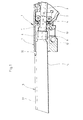
- FIG. 1 shows more or less schematically the front end of a jigsaw 1 with a housing 2, the part of which is no longer visible on the right in FIG. 2 surrounds a preferably electric drive motor in a manner known per se and ends in a handle for the jigsaw.
- the drive motor drives a lifting rod 3 back and forth (arrow A) in a manner known per se, the lifting rod 3 being slidably guided between two rollers 4, 5 and in addition to the back and forth movement in the direction of arrow A in the Usually another pendulum stroke uni performs a small angular amount in the direction of arrow B.
- the front free end of the lifting rod 3 projecting over the rollers 4, 5 is located in a recess 6 which is formed at the front end of the jigsaw 1 in its housing 2.
- the sleeve 9 is clamped with the lifting rod 3 such that the saw blade 8 is securely clamped between the inner wall of the sleeve 9 and the flank of the lifting rod 3 and the and executing pendulum movement of the lifting rod 3 with.
- the connection of the saw blade 8 with the lifting rod 3 is conventional and could also be carried out in a different way than described.
- the saw blade 8 has a saw toothing 14 in the usual way on its edge lying at the bottom in FIG. 1.
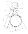
- FIG. 2 shows schematically the use of the jigsaw 1 from FIG. 1 when severing a tube 15, which is attached to a fixed, angular base 16 in a known manner, e.g. B. is supported with the help of a tension chain.
- the jigsaw 1 can be pivoted about an axis of rotation 17 relative to the base 16 and the tube 15 supported therein.
- This axis of rotation 17 is usually realized by a pivot pin which can be inserted into a bore at the front end 7 of the jigsaw housing 2 and which (in a manner not shown) is rigidly connected to the base 16 and its associated clamping device.
- the jigsaw 1 with its saw blade 8 can be pivoted relative to the pipe 15, starting from the position shown in solid lines in FIG. 2 into the position shown in broken lines in FIG. 2, in order to cut through the latter.
- the saw blade 8 has just entered the wall of the tube 15 in its upper position. In the lower, dash-dotted position, the saw blade is located shortly before it emerges from the tube wall.
- the pipe 15 to be cut is shown looking in the direction of the arrow C in Figure 2.
- an ideal straight saw cut 19, perpendicular to the pipe axis 18, is drawn on the right.
- the saw cut with conventional saw blades 8 is wavy, as shown at 21 in FIG.
- the saw cut 21 begins at right angles to the pipe axis 18 in the area 22 of the upper pipe wall. Subsequently, the saw sections carried out by the rear and front part of the saw blade 8 no longer run parallel to one another in the rear or front tube wall, but are curved in different ways.
- the cut 23 formed in the rear tube wall is still somewhat perpendicular to the tube axis 18 because the saw blade in the region of the rear tube wall is still largely stabilized by its attachment to the lifting rod 3 guided on all sides.
- the saw cut 24 in the front pipe wall is clearly curved, deviating from the rear saw cut 23, because the front end of the saw blade 8, which carries out this cut 24 and is far away from the clamping section 11 of the saw blade 8, tends to twist and bend.
- the two saw cuts in the rear and front tube wall naturally have to converge again, as indicated in FIG. 3 by reference number 25.
- the saw blade 8 emerges from the tube 15 at the bottom.
- the point 26 is additionally indicated by dash-dotted lines at which the saw blade 8 would have to emerge from the tube 15 at the bottom in an ideally running cut.
- the real section profile shown in FIG. 3 was determined and analyzed in lengthy investigations. Surprisingly, it was found that the real cutting profile can be approximated to the ideal cutting profile (reference number 19 in FIG. 3) completely or at least largely if the saw blade 8 is reinforced by a widening 31 in its front working section. This obviously counteracts bending and twisting of the saw blade 8, so that the cuts on the front and rear tube walls run parallel.
- the saw blade 8 is at the rear end of its backward stroke triggered by the lifting rod 3.
- the saw blade 8 has just reached the end of its forward stroke. It can be seen from FIG. 1 that the saw blade 8 partially enters the recess 6 at the front end 7 of the jigsaw with its working section having the toothing 14. Since the recess 6, in particular with respect to conventional saw blades, has a relatively small height, the widening 31 of the saw blade 8 which serves for reinforcement cannot be provided over the entire length of the toothing 14, but only as far as the saw blade 8 during the reverse stroke the lifting rod 3 ( Figure 1) does not enter the front end 7 of the jigsaw 1.
- the additional widening 31 of the saw blade serving for reinforcement is offset from the other width of the saw blade 8 by a rounded step 32, the step 32 being so far away from the clamping section 11 of the saw blade 8 that the Step 32 does not enter the front end 7 of the jigsaw 1 during the reverse stroke of the lifting rod 3.
- the additional widening 31 is located on the side of the saw blade 8 facing away from the saw teeth 14.
- the widening 31 could also be due to the area of the saw blade 8 entering the jigsaw housing 2 during the backward stroke of the lifting rod the saw teeth 14 bearing side of the saw blade 8 are provided.
- FIG. 4 shows a preferred embodiment of a saw blade according to the invention in individual representation and with the specification of typical dimensions.
- the clamping section 11 With a total length of 210 mm of the saw blade 8, the clamping section 11 has a width of 20 mm. In known saw blades, this is followed by a working section provided with saw teeth 14, which is usually about 28 mm wide. According to the invention, this working section is widened from level 32 to 32 mm, that is to say 4 mm wider than a normal saw blade.
- the back section of the saw blade 8 which enters the front end 7 of the jigsaw 1 when the saw blade 8 is moved back and forth has a length of approximately 70 mm.
- FIG. 4 The dimensions given in FIG. 4 are only to be understood as examples. They can be changed accordingly, especially in the case of longer saw blades 8 overall. Widenings 31 of the saw blade 8 in the range from 3 to 7, in particular 4 to 5 mm, have proven to be particularly favorable. A particularly advantageous thickness or thickness of the saw blade 8 is between approximately 2 and 2.5 mm, in particular 2.3 mm.
Landscapes
- Engineering & Computer Science (AREA)
- Mechanical Engineering (AREA)
- Sawing (AREA)
Applications Claiming Priority (2)
| Application Number | Priority Date | Filing Date | Title |
|---|---|---|---|
| DE4025259A DE4025259A1 (de) | 1990-08-09 | 1990-08-09 | Saegeblatt fuer eine motorgetriebene stichsaege |
| DE4025259 | 1990-08-09 |
Publications (2)
| Publication Number | Publication Date |
|---|---|
| EP0470385A2 true EP0470385A2 (fr) | 1992-02-12 |
| EP0470385A3 EP0470385A3 (en) | 1992-06-17 |
Family
ID=6411937
Family Applications (1)
| Application Number | Title | Priority Date | Filing Date |
|---|---|---|---|
| EP19910111473 Ceased EP0470385A3 (en) | 1990-08-09 | 1991-07-10 | Saw-blade for a motor-driven compass saw |
Country Status (2)
| Country | Link |
|---|---|
| EP (1) | EP0470385A3 (fr) |
| DE (1) | DE4025259A1 (fr) |
Cited By (2)
| Publication number | Priority date | Publication date | Assignee | Title |
|---|---|---|---|---|
| WO2012097896A1 (fr) * | 2010-12-22 | 2012-07-26 | Robert Bosch Gmbh | Lame de scie pour une scie sauteuse |
| US20170217038A1 (en) * | 2014-08-12 | 2017-08-03 | Berran Industrial Group, Inc. | Device and method for cutting hollow, thin-walled objects |
Family Cites Families (1)
| Publication number | Priority date | Publication date | Assignee | Title |
|---|---|---|---|---|
| US3945120A (en) * | 1974-04-25 | 1976-03-23 | Milwaukee Electric Tool Corporation | Vibration dampening and heat sink mechanism for a reciprocating power saw |
-
1990
- 1990-08-09 DE DE4025259A patent/DE4025259A1/de not_active Withdrawn
-
1991
- 1991-07-10 EP EP19910111473 patent/EP0470385A3/de not_active Ceased
Cited By (3)
| Publication number | Priority date | Publication date | Assignee | Title |
|---|---|---|---|---|
| WO2012097896A1 (fr) * | 2010-12-22 | 2012-07-26 | Robert Bosch Gmbh | Lame de scie pour une scie sauteuse |
| CN103260805A (zh) * | 2010-12-22 | 2013-08-21 | 罗伯特·博世有限公司 | 用于刺锯的锯片 |
| US20170217038A1 (en) * | 2014-08-12 | 2017-08-03 | Berran Industrial Group, Inc. | Device and method for cutting hollow, thin-walled objects |
Also Published As
| Publication number | Publication date |
|---|---|
| EP0470385A3 (en) | 1992-06-17 |
| DE4025259A1 (de) | 1992-02-13 |
Similar Documents
| Publication | Publication Date | Title |
|---|---|---|
| EP0543781B1 (fr) | Couteau | |
| EP2183072B1 (fr) | Machine-outil à main | |
| EP1513645B1 (fr) | Scie m canique pilotage manuel | |
| DE102004028992A1 (de) | Baumsäge | |
| WO2012107253A1 (fr) | Dispositif de support pour machine-outil | |
| DE8816871U1 (de) | Messer | |
| DE2311446A1 (de) | Halterung fuer ein saegeblatt, insbesondere einer stichsaege | |
| EP1955802B1 (fr) | Scie à métaux, en particulier scie sauteuse | |
| EP0377410A1 (fr) | Lime ou râpe | |
| EP0470385A2 (fr) | Lame de scie pour une scie à quichet actionné par moteur | |
| EP1922172B1 (fr) | Scie a main | |
| DE2021800A1 (de) | Saegeblatt | |
| EP0211182A2 (fr) | Scie de jardinier | |
| DE2231806C2 (de) | Hornhauthobel | |
| DE3347920A1 (de) | Saegeeinrichtung | |
| DE3230882C2 (de) | Mähfinger für Fingerbalkenmähwerke | |
| EP1245352A1 (fr) | Rabot refendeur à main destiné aux courroies | |
| EP0387562B1 (fr) | Barre de guidage pour scies à chaîne motorisées | |
| DE3012493A1 (de) | Vorrichtung zum schneiden von dichtungsprofilen aus elastormeren werkstoffen auf gehrung | |
| EP0257105A1 (fr) | Scie ébrancheuse | |
| DE4314004B4 (de) | Sägeblatt für eine Säge zum Schneiden von Gas- und/oder Porenbetonsteinen | |
| DE1503939C (de) | Sageblatt fur Stichsagemaschinen | |
| DE3111262A1 (de) | Stossmessermaschine zum zuschneiden von flachmaterial | |
| DE655818C (de) | Fuchsschwanzsaege | |
| DE289788C (fr) |
Legal Events
| Date | Code | Title | Description |
|---|---|---|---|
| PUAI | Public reference made under article 153(3) epc to a published international application that has entered the european phase |
Free format text: ORIGINAL CODE: 0009012 |
|
| AK | Designated contracting states |
Kind code of ref document: A2 Designated state(s): BE FR IT NL SE |
|
| PUAL | Search report despatched |
Free format text: ORIGINAL CODE: 0009013 |
|
| AK | Designated contracting states |
Kind code of ref document: A3 Designated state(s): BE FR IT NL SE |
|
| 17P | Request for examination filed |
Effective date: 19921125 |
|
| 17Q | First examination report despatched |
Effective date: 19940608 |
|
| STAA | Information on the status of an ep patent application or granted ep patent |
Free format text: STATUS: THE APPLICATION HAS BEEN REFUSED |
|
| 18R | Application refused |
Effective date: 19941128 |