EP0470400A2 - Signalerzeugungsmethode für Datenkopfstellung und Gerät dazu - Google Patents
Signalerzeugungsmethode für Datenkopfstellung und Gerät dazu Download PDFInfo
- Publication number
- EP0470400A2 EP0470400A2 EP91111798A EP91111798A EP0470400A2 EP 0470400 A2 EP0470400 A2 EP 0470400A2 EP 91111798 A EP91111798 A EP 91111798A EP 91111798 A EP91111798 A EP 91111798A EP 0470400 A2 EP0470400 A2 EP 0470400A2
- Authority
- EP
- European Patent Office
- Prior art keywords
- data head
- track
- information
- servo
- offset
- Prior art date
- Legal status (The legal status is an assumption and is not a legal conclusion. Google has not performed a legal analysis and makes no representation as to the accuracy of the status listed.)
- Granted
Links
Images


Classifications
-
- G—PHYSICS
- G11—INFORMATION STORAGE
- G11B—INFORMATION STORAGE BASED ON RELATIVE MOVEMENT BETWEEN RECORD CARRIER AND TRANSDUCER
- G11B21/00—Head arrangements not specific to the method of recording or reproducing
- G11B21/02—Driving or moving of heads
- G11B21/10—Track finding or aligning by moving the head ; Provisions for maintaining alignment of the head relative to the track during transducing operation, i.e. track following
-
- G—PHYSICS
- G11—INFORMATION STORAGE
- G11B—INFORMATION STORAGE BASED ON RELATIVE MOVEMENT BETWEEN RECORD CARRIER AND TRANSDUCER
- G11B5/00—Recording by magnetisation or demagnetisation of a record carrier; Reproducing by magnetic means; Record carriers therefor
- G11B5/48—Disposition or mounting of heads or head supports relative to record carriers ; arrangements of heads, e.g. for scanning the record carrier to increase the relative speed
- G11B5/54—Disposition or mounting of heads or head supports relative to record carriers ; arrangements of heads, e.g. for scanning the record carrier to increase the relative speed with provision for moving the head into or out of its operative position or across tracks
- G11B5/55—Track change, selection or acquisition by displacement of the head
- G11B5/5521—Track change, selection or acquisition by displacement of the head across disk tracks
- G11B5/5526—Control therefor; circuits, track configurations or relative disposition of servo-information transducers and servo-information tracks for control thereof
- G11B5/553—Details
- G11B5/5547—"Seek" control and circuits therefor
-
- G—PHYSICS
- G11—INFORMATION STORAGE
- G11B—INFORMATION STORAGE BASED ON RELATIVE MOVEMENT BETWEEN RECORD CARRIER AND TRANSDUCER
- G11B21/00—Head arrangements not specific to the method of recording or reproducing
- G11B21/02—Driving or moving of heads
- G11B21/08—Track changing or selecting during transducing operation
Definitions
- the present invention relates to a method and an apparatus for generating a data head positioning signal, and an apparatus for data head positioning that are necessary when a data head is moved to an arbitrary track containing information on a rotatable recording medium.
- servo-control scheme using servo plane or area has been employed widely wherein, a data head can achieve the positioning action toward the destination data track, by being guided by servo information written in over the whole plane of a recording medium.
- the sector-servo scheme has been proposed.
- positioning servo-sector has been (i.e. preliminarily written in) buried in. Then, when an arbitrary data track is selected, a data head is servo-tracked to a destination track based on the servo information of the servo-sectors,.
- this scheme only the information necessary for tracking control is provided. Therefore, it was a drawback that, in order to let the data head moves radically at high velocity, an extra positioning detector besides a data head must be provided, or data head position information must be supplied from the servo plane.
- the ratio of occupation from servo-sectors in the area of a recording medium necessarily increases. This induces a problem of resultant reduction of an available memory capacity in a given recording medium.
- An object of the present invention is to provide a data head positioning signal generating method and an apparatus therefore for accessing the data head on a disk-shaped information recording medium with a high speed and a high precision.
- the data head positioning signal generating method in accordance with the present invention comprises the steps of;
- the data head positioning signal generating apparatus in accordance with the present invention comprises;
- the servo patterns are discretely formed on the tracks of the recording medium.
- the above-mentioned servo pattern comprises a first area and a second area.
- the first area has at least two sub-servo-patterns of a periodic interval of the width of the M tracks.
- a relative position of the data head and a track is detected with a resolution of 1/(2"') of track width by using the two servo patterns.
- at least two burst patterns are disposed in the second area, and thereby a positional error of the data head from a center of an information track is precisely detected.
- a data head positioning signal having a dynamic range of the periodic interval of the width of M tracks can be generated by using data head position information obtained from the above-mentioned two areas. Consequently, even if the data head rushes to a target track with a high speed, the data head is stably positioned to the target track, and high speed and high reliability seek operation is realizable.
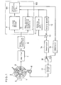
- FIG.1 is a block diagram of a fundamental embodiment of a data head positioning apparatus as the preferred embodiment of the present invention.
- a rotatable recording medium 1 such as a magnetic hard or flexible disk which is to be revolved by a known spindle motor (not shown in the figure) has a number of discrete servo-sectors 2,2... for recording the servo informations.
- the information or data of the servo-sectors 2 are buried beforehand (or preliminarily recorded) discretely with a predetermined pitch in a manner to be read by a data head 5 which runs in the circular direction on the information track on the recording medium plane.
- Data sectors 3,3... are disposed between said servo-sectors 2,2... for recording data to be recorded thereon.
- Information tracks 4,4... are provided in the data sectors on the recording medium plane.
- the information of the data sectors 3,3 can be written in and read out from the information tracks through the data head.
- a VCM (voice coil motor) positioner 6 is provided in a manner to make necessary moving (accessing) of the data head 5 to a selected information track by moving the data head 5 radically of the recording disk 1.
- An amplifier 7 amplifies signals reproduced by the data head 5.
- a servo information demodulator 8 receives reproduced signals from the amplifier 7 and detects servo-sectors 2, 2... which are placed discretely on a recording medium 1, thereby to extract only the servo information and outputs it.
- An in-track position decoder 9 decodes and detects the positions of the data head 5 inside the information tracks 4,4,...
- a data head position information recognition apparatus 10 recognizes and discriminates the relative position of the data head 5 with respect to the information tracks 4,4,... with a precision of 1/(2"') of the track width by using at least two servo patterns formed in a first area of the servo sector as will be described later.
- a data head positioning signal generating apparatus 100 calculates a distance in a radial direction of the recording medium between a track decided arbitrarily and the data head with the resolution of 1/(2"') of the track width by using the output of the data head positional information recognition means 10 and a central processing unit (UCPU) 101.
- a data head positioning signal having a dynamic range of the width of M tracks and a periodic interval of the width of M tracks is generated from the data head positioning signal generating apparatus 100.
- a velocity instruction part 11 instructs a target velocity, corresponding to the distance to a selected destination track or the number of tracks to cross over to reach the destination track, at the time of the track access control for accessing or transferring the data head to the selected information track.
- the velocity instruction part 11 is realized with a ROM table or the like.
- the velocity instruction part 11 may be such one that, an arithmetic processing on the measured data is made by using a function which is prescribed in the instruction part 11, thereby to issue output, every time the distance to the destination track or the number of tracks to cross over to reach the destination track is measured.
- a velocity detector 12 performs arithmetic processing every time when the data head 5 passes a servo-sector 2 by receiving as its input data head position information of high resolution from the data head position recognition apparatus 10, thereby to output radial moving velocity of the data head in the radial direction of the recording medium.
- An error amplifier 13 is for performing an error calculation between the outputs of the above-mentioned velocity instruction part 11 and the velocity detector 12.
- the output of this error amplifier 13 is supplied through a compensator 14 and a switch 16 to a current driver 17, which supplies the current to the VCM positioner 6 responding to the output of the compensator 14, and thus a track access control loop is constituted.
- the tracking control loop which makes the data head 5 track a selected information track is constituted by supplying the output of the data head positioning signal generating apparatus 100 to the current driver 17 through the compensator 15 and the switch 16.
- FIG.2 is an actual example (of servo-pattern) of the circularly discrete servo-sectors 2 buried beforehand in the information tracks 4 on a rotatable recording medium in one embodiment of the present invention shown in FIG.1.
- numeral 3 represents a data sector.
- This servo-sector 2 comprises: a burst part 18, an erase part 19 for detecting the servo-sector, a track code part 20 for acquiring the track address information, and a positional information 21 for acquiring the position deviation information from the on-track of the data head during the tracking control time.
- the erase part 19 is taken so as to give a maximum erasing time on the information tracks of the recording medium 1.
- the positional information 21 comprises burst signals a and burst signals ;8, and they are set with a lateral shift as large as a half track width with respect to respective tracks of the data sectors 3. Writing in on the servo-sector is prohibited.
- the above-mentioned track code part 20 comprises by burying therein a synchronization bit (hereinafter: sync bit) S, a zone discrimination part 20a, a second servo pattern 20c, a third servo pattern 20d and a first servo pattern 20b.
- the sync bit part S is for indicating the end of the DC erase part and the beginning of the track code part 20.
- the zone discrimination part 20a comprises three dibit patterns A, B, and C and is for discriminating between the guard zone and the data zone and the sorts of data zones.
- the first servo-pattern 20b comprises a three-phase dibit patterns G, H, and I each having a period of as much as three tracks.
- the second servo-pattern 20c comprises two dibit patterns D and E each having a period of as much as 12 tracks and a shift of 3 tracks therebetween.
- the third servo pattern 20d comprises a dibit pattern F having a period of as much as 6 tracks and a shift of at least of 1.5 tracks from the second servo pattern 20c.
- the second servo-pattern 20c having two dibit patterns and the third servo-pattern 20d are placed on one side of the first servo-pattern 20b
- another mode may be embodied such that the second servo-pattern comprising two dibit patterns are separated and placed respectively on both sides of the first servo-pattern. It is further possible to place the second servo-pattern on one side of the first servo-pattern and place the third servo-pattern on another side of the first servo-pattern. Furthermore, it is also possible to place each of the second servo-pattern and the third servo-pattern alternately with respect to the first servo-pattern comprising three dibit patterns. At the time of record and reproduction to and from the data track through the data head 5, the data head 5 runs across successive two tracks of the servo-sector 2.
- waveform reproduced from the data head 5 becomes as shown in FIG.3. That is, in the burst part 18 a specified reference signal is reproduced. In the erase part 19, no signal is reproduced. And in the track code part 20, the following signals are reproduced corresponding to respective servo patterns respectively: at the sync bit position S, at the zone discrimination positions A, B, and C, at the second servo-pattern positions D and E, at the third servo-pattern position F, and at the first servo-pattern positions G, H and I. And further in the position information 21, the signals are reproduced respectively at the burst signal a and the burst signal ;8.
- reproduced signal becomes as follows: at the positions S, A, B, C, E, F, G, and I, output becomes 1; at the positions D and H, output becomes 0; and at the burst positions a and (3, output becomes 1/2. It is needless to mention that the above-mentioned reproduced signal changes depending upon the track position on a recording medium on which the data head 5 is present.
- the track position of the data head 5 with respect to the recording medium is detected with a high precision. Then, toward the destination track thus selected, the seek action is performed to achieve the data head positioning action.
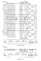
- FIG.4 shows an ideal output state timing chart of a reproduced waveform at the time when the data head 5 is driven to move with a slow velocity over servo-sectors from an inside track to an outside track of a recording medium as shown in FIG.2. Because the data head 5 has a finite width, the slope part of respective reproduced signal in FIG.4 is, determined by the output value responding to the occupation ratio of dibit pattern width to the data head width at the point of time when the data head passes respective dibit patterns. In FIG.4, those numbers from 00 to 11 correspond to the track numbers of 12 track periods shown in the left end blocks in FIG.2. Cyclic Alphabetical notations from a to 1 represent servo-track numbers of 12 track periods which are radially shifted as large as a half track width.
- reproduced signals D, E, and F obtained from the second and the third servo-patterns are processed to binary-valued signals determined by a prescribed threshold level.
- the reproduced signals G, H, and I obtained from the first servo-pattern are peak-held and thereafter respective values are compared and converted into binary-valued information.
- the above-mentioned two different groups of binary-valued informations which are obtained from a first group information D, E and F and from a second group information G, H and I of the reproduced signals of D, E, F and G, H, I, are let to be a first binary-valued information.
- a predetermined offset is added to a signal in which the lowest value among the above-mentioned signals G, H, and I is held. Then, by performing again a next comparison of this offset value with the corresponding signal, a second binary coded information is obtained.
- the position of the data head 5 on the servo-track is recognized accurately up to a precision of 1/(2 2 ) of the track width.
- the second servo-patterns D and E have a period of 12 tracks, a mutual delay of 6 tracks, hence have a mutual overlap of 3 tracks, and produce from their reproduced signal the signal E and the signal D. Accordingly, as far as the reproduced signals are ideal, it is possible to discriminate 3 tracks out of those 12 tracks. However, since the data head has a finite width, the reproduced output does not change digitally and since the reproduced waveforms are influenced by the response characteristics of the recording medium or of the data head, it is difficult to discriminate digitally 3 tracks out of 12 tracks.
- FIG.5 shows, likewise in FIG.4, an ideal output state timing chart of signals G, H, and I at the time when the data head is let to move with a slow velocity over servo-sectors from an inside track to an outside track of a recording medium as shown in FIG.2.
- the variation is expanded and shown.
- the signals G, H, and I are shown with overlapping them to each other.
- the peak value of the output of the signals G, H, and I are represented after normalizing them (the maximum value is taken to be 1).
- the detected codes of the signals D, E, and F to be "H” "H” "L", as is understood from TABLE 1
- the data head is to be present at some place on the tracks of d, e, or f in the servo-sector.
- the peak value of the reproduced signal from the signals G, H, and I are respectively 22, 23, and 24 as shown in FIG.5, it is understood that value of G signal is larger than value of H signal, value of H signal is larger than value of I signal, and value of I signal is smaller than value of G signal. That is, when an examination of relations such as
- an offset expressed by is added onto the G signal, H signal, or I signal.
- the double sign is determined by the (N-1)-th binary-valued information such that: when the binary-valued information is "H", the - sign must be taken, whereas when it is "L”. The + sign must be taken.
- Table 2 tabulates the first binary-valued information described above, that is, those information in accordance with G signal, H signal, and I signal of 3 track periods in the servo-sector, and also those cases of value of G signal > value of H signal, value of H signal > value of I signal, and value of I signal > value of G signal.
- alphabetical notations, (a--1), ), (a 1 , a 2 --11, 12) are the same ones as shown in FIG.5. Since it never takes place that the binary-valued informations becomes "H, H, and H or L, L, and L", they are not included in the table. Now, reference of this table is explained taking an example.
- the second binary-valued information is obtained.
- the second binary information discrimination of the data head position is achieved with a precision of 1/(2 2 ) of the track width.
- the leftest column mark indicates the signal names to which the first offset was added, and mark means "no need of adding the offset".
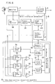
- FIG.6 is a block diagram which show one embodiment of further details of a data head position information recognition apparatus 10 and a servo information demodulator 8 of a data head positioning apparatus.
- the signals After detecting signals by the data head 5 from the recording medium 1 the signals are is amplified by an amplifier 7, and the output thereof is supplied to an AGC amplifier 38.
- the AGC amplifier 38 normalizes the output value using such as a burst part 18 buried in the servo-sector 2.
- a servo information demodulator 18 comprises the AGC amplifier 38, a binary-converting circuit 39 and a sector-counter/gate-generator 41.
- the binary-converting circuit 39 converts the signal normalized by the AGC amplifier with a prescribed threshold value, an erase part detector 40, which finds out the erase part 19 having a longest space part out of successive binary-valued signals.
- the sector-counter/gate-generator 41 detects the erase part 19 and at the same time lets the counter part thereof start to generate gate signal for detecting signals A to I in the track code 20 and a-burst and ⁇ 3-burst representing in-track position information both of which are buried and formed in a servo-sector 2; the sector-counter/gate generator 41 further generates gate signal for discriminating the next-coming servo-sector from the data sector 3.
- the in-track position decoder 9 receives gate instructions from the sector-counter/gate-generator 41, thereby receives only the a-burst and ⁇ 3-burst representing in-track position information and performs an arithmetic calculation of "a-burst - (3-burst" to detect the in-track position during the time of tracking control.
- the data head position information recognition apparatus 10 comprises a memory circuit 36, peak holders 26, 27 and 28 for G, H and I signals, respectively, comparators 29, 30 and 31, a first and a second latch 32 and 35, respectively, an offset adder 34, a memory 36 and a data head-position-informing discriminator 37.
- the memory circuit 36 memorizes momentarily binary-valued information of signals A, B, C, D, E, and F out of binary-valued signals binary-converted by a binary-converting circuit 39.
- the peak holder G 26, the peak holder H 27, and the peak holder I 28 receive the gate instruction from the sector-counter/gate-generator 41 and hold respective peak values of the signals G, H, and I.
- the comparator 29 compares the peak value of the peak holder G 26 and the peak value of the peak holder H 27.
- the comparator 30 compares the peak value of the peak holder H 27 and the peak value of the peak holder I 28.
- the comparator 31 compares the peak value of the peak holder I 28 and the peak value of the peak holder G 26.
- the first latch 32 holds binary-valued information of the comparators 29, 30 and 31 and constitutes a first binary-valued information together with the binary-valued information of the memory 36.
- the offset decoder 33 determines to which peak holder among G 26, H 27, and I 28 a first offset is to be added, depending on the decoding schemes in the aforementioned TABLE 3.
- the offset adder 34 adds a prescribed offset value to either one of the peak holders G 26, H 27, and I 28 in compliance with the instruction of the above-mentioned offset decoder 33.
- the second latch 35 holds the result of comparison between the peak value of the peak holder to which an offset was added by the offset adder 34 and the peak value of the corresponding peak holder and forms a second binary-valued information.
- the data head position information discriminator 37 discriminates the relative position of the data head with respect to the servo-track by using the first binary-valued information consisting of the contents of the above-mentioned memory circuit 36 and the first latch 32 and by using the second binary-valued information consisting of the contents of the second latch 35.
- the data head position information recognition apparatus 10 becomes capable of discriminating the relative position relation of the data head with respect to the track in the servo-track with a precision up to 1/(2 2 ) of the track width. Accordingly, at the time of controlling the track access, it becomes possible to recognize the moving velocity of the data head as precisely as four (4) times of that of prior art, thereby achieving a high accuracy velocity control of the data head.
- the position discrimination of the data head using TABLE 1, TABLE 2, TABLE 3, and TABLE 4 can be made by a hardware utilizing such as ROM table, or can be made by a software utilizing such as a micro-CPU and a program.
- FIG.7 is a block diagram for a case that the constitution is devised so that the relative position of the data head position information recognition apparatus 10 with respect to servo-tracks 2,2--- of the data track 4? can be discriminated accurately up to a precision of 1/(2"') of the track width.
- the data head position information discriminator 37 performs the following processes: It selects a peak holder 26, 27 or 28 to which a first offset is to be added and instructs a first offset value to be added to the offset adder 34 based on a first binary-valued information formed by the memory circuit 36 and the first latch 32.
- the data head position information discrimination element 37 selects a peak holder 26, 27 or 28 to which a second offset is to be added and instructs a second offset value to be added to the offset adder 34. And it performs a comparison between a peak value held in the peak holder to which the offset was already added and a peak value of a paired peak holder and thereby forms a third binary-valued information on the third latch.
- FIG.8 is a diagram of an "expanded positional signal" having a periodic interval of 12 track width (an interval of 12 times of on track pitch).
- the diagram is generated by the data head positional signal generating apparatus 100, which comprises the in-track position detector 9, the data head positional information recognition apparatus 10 and the central processing unit 101.
- the periodic interval of the position signal is 12 track width.
- a target track is positioned at the center of the position signal. In a range within about ⁇ 1/2 of a track width adjacent to the center, a position signal having a linear characteristic is generated so as to enable fine detection of the data head position.
- Other parts of the position signal in the range of 12 track width are step-wave signals having a resolution of 1/(2 2 ) of the information track width.
- the position of the data head 5 is detected with the resolution of 1/(2 2 ) of the information track width, and an expanded position signal is represented by range codes of 0 --- 47.
- the numerals 0 --- 47 representing ranges of the position of the data head correspond to the representations ao 4 --- lo4 in the table 4, respectively.
- FIG.9 is a flow chart of a method for generating the expanded position signal shown in FIG.8 by using the data head positional information recognition apparatus 10 and the in-track position decoder 9 which recognizes a relative position between the data head and a target track with the resolution of 1/(2 2 ) of the information track width.
- the data head 5 After start of the seek action from the 10-th track to the 81 st track, the data head 5 detects a position represented by the range code in the resolution of 1/(2 2 ) of the information track width. Then a travel distance and a velocity is calculated on the basis of a position detected at last passing of a servo sector and a current position detected by passing of next servo sector.
- the travel distance in the event that the range code value of the current position of the data head is small and the previous range code value where the data head has previously positioned is large, the travel distance is obtained by the calculation of "48-(previous range code) + (current range code)".
- the expanded position signal having the PES of "-20A” is applied to the VCM position 6 through the compensator 15, the switch 16 and the current driver 17.
- the moving velocity of the data head depends on the PES of the expanded position signal.
- the center of the target track (range code 36) is made to place at the center of the expanded position signal (zero level position) as shown in FIG.8. Consequently, a control signal in the control system using the expanded position signal has a positive value after the center of the target track and has a negative value before the center of the target track. Therefore, when the data head approaches a target track from the outer part or the inner part of the recording medium, the expanded position signal approaches zero from a positive value + 24 or a negative value -24.
- the range code difference P has entered within the range of ⁇ 2 (-2 ⁇ P ⁇ 2) (Step 4)
- the positional error between the data head and the center of the target track is detected by using the burst information (Step 13).
- control mode of the data head 5 is changed to the tracing control mode (position control mode) from the seek mode (velocity control mode).
- the expanded position signal having a positive value is generated (for example +24 and below) (Step 8 and 10).
- the PES becomes +20A as shown by steps 12 in the flow chart of FIG.9.
- the positional error between the data head and the center of the target track is detected by using the burst information.
- a velocity instruction signal for instructing a moving velocity of the data head is output from the velocity instruction part 11.
- the velocity instruction signal has a value corresponding to a distance between the target track and the current position of the data head 5.
- the moving velocity of the data head 5 is detected by the velocity detector 12, and a difference between the instructed velocity and the detected velocity is detected by the error amplifier 13.
- the output of the error amplifier 13 is applied to the VCM positioner 6, and the data head 5 is moved to the target track with the instructed velocity.
- a range code is detected at every passing of the servo sectors by the data head 5, and the position of the data head 5 is detected with the resolution of 1/(2 2 ) of the information track width by the data head position information recognition apparatus 10 of the data head positioning signal generating apparatus 100. Then, the travel distance of the data head 5 is calculated on the basis of the range code of the current position and the range code of the last position of the data head 5. In the data head positioning signal generating apparatus 100, the travel distance represented by the range code difference is calculated by subtracting the current position of the data head 5 from a travel distance calculated in advance ((target track number - the track number of the current position) x 4), and the rest of the distance is obtained.
- the expanded position signal of the periodic interval of 12 tracks is generated by the data head positioning signal generating apparatus 100.
- changeover from the velocity control mode to the tracing control mode is preferably before 2 or 3 tracks of the target track.
- the data head arrives at the position before 6 track of the target track, it is recommendable that the data head is moved in the velocity control mode until before 2 or 3 tracks of the target track, and at that position, the velocity control mode is changed to the tracing control mode by switching the switch 16 to a contact 16B. Thereafter, the data head 5 is settled to the center of the target track on the basis of the PES calculated in compliance with the expanded position signal which has the range code zero at the center of the target track.
- FIG.10(a) is the diagram of a settling time of the data head positioning apparatus in the prior art
- FIG.10(b) is the diagram of a settling time of the data head positioning in the present invention.
- Ordinates designate a track pitch
- abscissas designate settling times.
- rush velocities of the data head (1.25 cm/s, 2.5 cm/s, 5 cm/s, 10 cm/s and 15 cm/s) are parameters.
- the track pitch graduated at the starting point of each curve represents the rush position of the data head.
- These diagrams show the expanded position signal in the resolution of 1/(2 2 ) of the information track width based on a sampling time of 208 usec.
- the dynamic range of the position signal is about ⁇ 1/2 tracks, and the control mode is changed from the velocity control mode to the tracing control mode before 1/2 tracks of the target track.
- the data head In cases of 1.25 cm/s and 2.5 cm/s of rush velocity, the data head is settled to the target track within 3 ms, though there is an overshoot on the travel thereof. In case of 5 cm/s of rush velocity, the data head is not settled to the target track in the given dynamic range of the position signal because of an excessive rush velocity. Thus the data head falls in seek error.
- the dynamic range of the position signal is about ⁇ 6 tracks, and the control mode is changed from the velocity control mode to the tracing control mode before 3 tracks of the target track.
- the data head In case of 5 cm/s rush velocity, the data head is settled to the target track with a slight undershoot on the travel thereof. In case of 15 cm/s, the data head is settled to the target track with a slight overshoot on the travel thereof. In case of 5 cm/s, the data head is satisfactorily settled to the target track.
- the data head can be rushed to the target track with such a high velocity by using the expanded position signal, and a high velocity access of the data head is realizable. In other words, even if the rush velocity deviates from a predetermined value, the data head is safely settled to the target track, and reliability in seek operation of the data head is improved.
Landscapes
- Moving Of The Head To Find And Align With The Track (AREA)
- Moving Of Head For Track Selection And Changing (AREA)
Applications Claiming Priority (2)
| Application Number | Priority Date | Filing Date | Title |
|---|---|---|---|
| JP2189089A JP2591270B2 (ja) | 1990-07-16 | 1990-07-16 | ヘッド位置決め信号生成方法及び生成装置とヘッド位置決め装置 |
| JP189089/90 | 1990-07-16 |
Publications (3)
| Publication Number | Publication Date |
|---|---|
| EP0470400A2 true EP0470400A2 (de) | 1992-02-12 |
| EP0470400A3 EP0470400A3 (en) | 1992-09-09 |
| EP0470400B1 EP0470400B1 (de) | 1996-05-22 |
Family
ID=16235147
Family Applications (1)
| Application Number | Title | Priority Date | Filing Date |
|---|---|---|---|
| EP91111798A Expired - Lifetime EP0470400B1 (de) | 1990-07-16 | 1991-07-15 | Signalerzeugungsmethode für Datenkopfstellung und Gerät dazu |
Country Status (4)
| Country | Link |
|---|---|
| EP (1) | EP0470400B1 (de) |
| JP (1) | JP2591270B2 (de) |
| KR (1) | KR930006450B1 (de) |
| DE (1) | DE69119661T2 (de) |
Cited By (1)
| Publication number | Priority date | Publication date | Assignee | Title |
|---|---|---|---|---|
| DE4442112A1 (de) * | 1993-11-27 | 1995-06-01 | Samsung Electronics Co Ltd | Digitale Servosteuerungs-Vorrichtung und -Verfahren für ein Datenspeichersystem, welches ein Platten-Aufzeichnungsmedium verwendet |
Family Cites Families (4)
| Publication number | Priority date | Publication date | Assignee | Title |
|---|---|---|---|---|
| US3994016A (en) * | 1975-03-31 | 1976-11-23 | Honeywell Information Systems, Inc. | Head positioning servo system for disk drives |
| DE3120327A1 (de) * | 1981-05-22 | 1982-12-09 | Ibm Deutschland Gmbh, 7000 Stuttgart | Verfahren und anordnung zum kompensieren von signaleinbruechen in von magnetischen aufzeichnungstraegern gelesenen signalen |
| JPS59165279A (ja) * | 1983-03-11 | 1984-09-18 | Toshiba Corp | ヘツドの位置決め方式 |
| US4766508A (en) * | 1986-10-02 | 1988-08-23 | Eastman Kodak Company | Burst integral detecting embedded servo disk tracking system |
-
1990
- 1990-07-16 JP JP2189089A patent/JP2591270B2/ja not_active Expired - Lifetime
-
1991
- 1991-07-15 EP EP91111798A patent/EP0470400B1/de not_active Expired - Lifetime
- 1991-07-15 DE DE69119661T patent/DE69119661T2/de not_active Expired - Lifetime
- 1991-07-15 KR KR1019910012012A patent/KR930006450B1/ko not_active Expired - Lifetime
Cited By (4)
| Publication number | Priority date | Publication date | Assignee | Title |
|---|---|---|---|---|
| DE4442112A1 (de) * | 1993-11-27 | 1995-06-01 | Samsung Electronics Co Ltd | Digitale Servosteuerungs-Vorrichtung und -Verfahren für ein Datenspeichersystem, welches ein Platten-Aufzeichnungsmedium verwendet |
| DE4442112C2 (de) * | 1993-11-27 | 2000-03-02 | Samsung Electronics Co Ltd | Steuerverfahren zur Steuerung eines Aufzeichnungs-/Wiedergabekopfes |
| US6118616A (en) * | 1993-11-27 | 2000-09-12 | Samsung Electronics Co., Ltd. | Digital servo control method for controlling a head driver for moving a head to a target track |
| US6243226B1 (en) | 1993-11-27 | 2001-06-05 | Samsung Electronics Co., Ltd. | Apparatus and method for digital servocontrol in a data storage system using disk recording media |
Also Published As
| Publication number | Publication date |
|---|---|
| KR920003296A (ko) | 1992-02-29 |
| DE69119661T2 (de) | 1997-01-09 |
| EP0470400B1 (de) | 1996-05-22 |
| DE69119661D1 (de) | 1996-06-27 |
| JP2591270B2 (ja) | 1997-03-19 |
| EP0470400A3 (en) | 1992-09-09 |
| JPH0474370A (ja) | 1992-03-09 |
| KR930006450B1 (ko) | 1993-07-16 |
Similar Documents
| Publication | Publication Date | Title |
|---|---|---|
| US5335123A (en) | Apparatus and method for head-positioning on a rotatable recording medium | |
| KR0124052B1 (ko) | 고성능 디스크 드라이브, 이 디스크 드라이브내의 서보 섹터 패턴 및 이 디스크 드라이브에서 데이타 변환기 헤드의 위치를 결정하는 방법 | |
| US5771131A (en) | Tracking in hard disk drive using magnetoresistive heads | |
| US5063549A (en) | Optical disk apparatus | |
| US4928192A (en) | Process for identifying disks and automatically configuring a disk drive system | |
| EP0121145A1 (de) | System zur Lageermittlung eines Lese-Schreibkopfes bei einem Plattendatenträger mit Daten- und Servosektoren | |
| EP0183699A4 (de) | Servoschablone. | |
| EP0088554A1 (de) | Verfahren und Vorrichtung zur Lageermittlung und Vorrichtung zum Positionieren eines Schreib-Lesekopfes während der Suchoperation bei einem Plattenspeicher mit Daten und Servosektoren | |
| JPS5862870A (ja) | 磁気ディスク装置 | |
| JPH04274064A (ja) | グレイコードを用いたディスクドライブサーボシステム | |
| US5305159A (en) | Magnetic disk apparatus | |
| US4524398A (en) | Velocity control device for magnetic disc apparatus and method therefor | |
| EP0273546B1 (de) | Servosystem für ein Plattengerät | |
| US5396380A (en) | Resolution enhancement of absolute track position using iterative process and position bursts with track following capability | |
| KR100202350B1 (ko) | 디스크 메모리장치 | |
| US4636883A (en) | Magnetic head control apparatus | |
| US5285330A (en) | Apparatus for controlling moving speed of magnetic head | |
| EP0470400A2 (de) | Signalerzeugungsmethode für Datenkopfstellung und Gerät dazu | |
| US5402287A (en) | Resolution enhancement of absolute track position using iterative process and position bursts | |
| US5056076A (en) | Method for controlling the rotational velocity of an information recording disk | |
| JP2616175B2 (ja) | ヘッド位置決め信号生成方法及び生成装置とヘッド位置決め装置 | |
| US4905109A (en) | Process for optimizing head position to overcome disk misclamping and imperfections | |
| JP2765266B2 (ja) | ヘッド位置認識方法、ヘッド速度演算方法及びヘッド移動速度制御装置 | |
| JPH05159488A (ja) | ヘッド位置認識方法、速度演算方法およびヘッド移動速度制御装置 | |
| JPH1074371A (ja) | 磁気ディスク装置 |
Legal Events
| Date | Code | Title | Description |
|---|---|---|---|
| PUAI | Public reference made under article 153(3) epc to a published international application that has entered the european phase |
Free format text: ORIGINAL CODE: 0009012 |
|
| 17P | Request for examination filed |
Effective date: 19910715 |
|
| AK | Designated contracting states |
Kind code of ref document: A2 Designated state(s): DE GB IT |
|
| PUAL | Search report despatched |
Free format text: ORIGINAL CODE: 0009013 |
|
| AK | Designated contracting states |
Kind code of ref document: A3 Designated state(s): DE GB IT |
|
| 17Q | First examination report despatched |
Effective date: 19941205 |
|
| GRAH | Despatch of communication of intention to grant a patent |
Free format text: ORIGINAL CODE: EPIDOS IGRA |
|
| GRAA | (expected) grant |
Free format text: ORIGINAL CODE: 0009210 |
|
| AK | Designated contracting states |
Kind code of ref document: B1 Designated state(s): DE GB IT |
|
| PG25 | Lapsed in a contracting state [announced via postgrant information from national office to epo] |
Ref country code: IT Free format text: LAPSE BECAUSE OF FAILURE TO SUBMIT A TRANSLATION OF THE DESCRIPTION OR TO PAY THE FEE WITHIN THE PRE;WARNING: LAPSES OF ITALIAN PATENTS WITH EFFECTIVE DATE BEFORE 2007 MAY HAVE OCCURRED AT ANY TIME BEFORE 2007. THE CORRECT EFFECTIVE DATE MAY BE DIFFERENT FROM THE ONE RECORDED.SCRIBED TIME-LIMIT Effective date: 19960522 |
|
| REF | Corresponds to: |
Ref document number: 69119661 Country of ref document: DE Date of ref document: 19960627 |
|
| RIN2 | Information on inventor provided after grant (corrected) |
Free format text: SHIMIZU, RYOSUKE * TAKAOKA, TETSUROU * YOSHIURA, TSUKASA * WAKABAYASHI, NORIAKI |
|
| PLBE | No opposition filed within time limit |
Free format text: ORIGINAL CODE: 0009261 |
|
| STAA | Information on the status of an ep patent application or granted ep patent |
Free format text: STATUS: NO OPPOSITION FILED WITHIN TIME LIMIT |
|
| 26N | No opposition filed | ||
| REG | Reference to a national code |
Ref country code: GB Ref legal event code: IF02 |
|
| PGFP | Annual fee paid to national office [announced via postgrant information from national office to epo] |
Ref country code: DE Payment date: 20100707 Year of fee payment: 20 |
|
| PGFP | Annual fee paid to national office [announced via postgrant information from national office to epo] |
Ref country code: GB Payment date: 20100714 Year of fee payment: 20 |
|
| REG | Reference to a national code |
Ref country code: DE Ref legal event code: R071 Ref document number: 69119661 Country of ref document: DE |
|
| REG | Reference to a national code |
Ref country code: DE Ref legal event code: R071 Ref document number: 69119661 Country of ref document: DE |
|
| REG | Reference to a national code |
Ref country code: GB Ref legal event code: PE20 Expiry date: 20110714 |
|
| PG25 | Lapsed in a contracting state [announced via postgrant information from national office to epo] |
Ref country code: GB Free format text: LAPSE BECAUSE OF EXPIRATION OF PROTECTION Effective date: 20110714 |
|
| PG25 | Lapsed in a contracting state [announced via postgrant information from national office to epo] |
Ref country code: DE Free format text: LAPSE BECAUSE OF EXPIRATION OF PROTECTION Effective date: 20110716 |