EP0470428A2 - Dispositif de verrouillage de couvercle pour centrifuges de laboratoire, tournant à des vitesses moyennes ou élevées - Google Patents
Dispositif de verrouillage de couvercle pour centrifuges de laboratoire, tournant à des vitesses moyennes ou élevées Download PDFInfo
- Publication number
- EP0470428A2 EP0470428A2 EP91112293A EP91112293A EP0470428A2 EP 0470428 A2 EP0470428 A2 EP 0470428A2 EP 91112293 A EP91112293 A EP 91112293A EP 91112293 A EP91112293 A EP 91112293A EP 0470428 A2 EP0470428 A2 EP 0470428A2
- Authority
- EP
- European Patent Office
- Prior art keywords
- bolt
- lock according
- lid lock
- lid
- opening
- Prior art date
- Legal status (The legal status is an assumption and is not a legal conclusion. Google has not performed a legal analysis and makes no representation as to the accuracy of the status listed.)
- Granted
Links
- 230000008878 coupling Effects 0.000 claims description 5
- 238000010168 coupling process Methods 0.000 claims description 5
- 238000005859 coupling reaction Methods 0.000 claims description 5
- 230000009467 reduction Effects 0.000 claims description 3
- 230000009172 bursting Effects 0.000 description 2
- 230000035939 shock Effects 0.000 description 2
- 230000008901 benefit Effects 0.000 description 1
- 230000005540 biological transmission Effects 0.000 description 1
- 230000000295 complement effect Effects 0.000 description 1
- 230000002950 deficient Effects 0.000 description 1
- 238000006073 displacement reaction Methods 0.000 description 1
- 230000003993 interaction Effects 0.000 description 1
- 230000009191 jumping Effects 0.000 description 1
- 230000036316 preload Effects 0.000 description 1
Images




Classifications
-
- B—PERFORMING OPERATIONS; TRANSPORTING
- B04—CENTRIFUGAL APPARATUS OR MACHINES FOR CARRYING-OUT PHYSICAL OR CHEMICAL PROCESSES
- B04B—CENTRIFUGES
- B04B7/00—Elements of centrifuges
- B04B7/02—Casings; Lids
- B04B7/06—Safety devices ; Regulating
-
- Y—GENERAL TAGGING OF NEW TECHNOLOGICAL DEVELOPMENTS; GENERAL TAGGING OF CROSS-SECTIONAL TECHNOLOGIES SPANNING OVER SEVERAL SECTIONS OF THE IPC; TECHNICAL SUBJECTS COVERED BY FORMER USPC CROSS-REFERENCE ART COLLECTIONS [XRACs] AND DIGESTS
- Y10—TECHNICAL SUBJECTS COVERED BY FORMER USPC
- Y10S—TECHNICAL SUBJECTS COVERED BY FORMER USPC CROSS-REFERENCE ART COLLECTIONS [XRACs] AND DIGESTS
- Y10S292/00—Closure fasteners
- Y10S292/69—Washing machine or stove closure latch
-
- Y—GENERAL TAGGING OF NEW TECHNOLOGICAL DEVELOPMENTS; GENERAL TAGGING OF CROSS-SECTIONAL TECHNOLOGIES SPANNING OVER SEVERAL SECTIONS OF THE IPC; TECHNICAL SUBJECTS COVERED BY FORMER USPC CROSS-REFERENCE ART COLLECTIONS [XRACs] AND DIGESTS
- Y10—TECHNICAL SUBJECTS COVERED BY FORMER USPC
- Y10T—TECHNICAL SUBJECTS COVERED BY FORMER US CLASSIFICATION
- Y10T292/00—Closure fasteners
- Y10T292/08—Bolts
- Y10T292/096—Sliding
- Y10T292/0961—Multiple head
- Y10T292/0962—Operating means
-
- Y—GENERAL TAGGING OF NEW TECHNOLOGICAL DEVELOPMENTS; GENERAL TAGGING OF CROSS-SECTIONAL TECHNOLOGIES SPANNING OVER SEVERAL SECTIONS OF THE IPC; TECHNICAL SUBJECTS COVERED BY FORMER USPC CROSS-REFERENCE ART COLLECTIONS [XRACs] AND DIGESTS
- Y10—TECHNICAL SUBJECTS COVERED BY FORMER USPC
- Y10T—TECHNICAL SUBJECTS COVERED BY FORMER US CLASSIFICATION
- Y10T292/00—Closure fasteners
- Y10T292/08—Bolts
- Y10T292/1099—Screw
Definitions
- the invention relates to a lid lock for medium to high-speed laboratory centrifuges with housing and lid, an axially movable bar, which has at least one latch engagement with a latch opening on the lid.
- Such interlocks are known. They are made by relays. Such relays depend on the power supply. If the latter fails, the lock can open. When using a magnet, a locking position can be maintained even in the event of a power failure. However, it can be released if, in the event of damage, an impact or impact hits an element of the locking device. This is particularly serious when a relay working with magnetic force, in particular with spring support, is effective. Vibrations can then occur which arbitrarily permit opening.
- a locking device is known with a rotary latch which can be actuated by a handle or a corresponding drive.
- the axle pin To lock a plate, the passage of an axle pin through a special hole in the other element is provided, the axle pin having a head with a cross section which, when the axle pin is rotated, creates the engagement behind an abutment.
- a manual operation with a handle head is shown.
- the axis pin can only reach the area of the locking possibilities through slots in a certain orientation.
- the locking is provided at right angles to a plate that is practically arranged as a lid.
- This known design is defective because strikes, vibrations or stops on cross pins can lead to the opening of the closure.
- the invention is therefore based on the object to provide a lid lock for medium and high-speed centrifuges, which remains securely in its locked position even in the event of failures, be it due to the bursting of the centrifuge rotor or even in the event of a power failure to actuate the bolt the lock itself is exposed to shock or impact stresses, while at the same time creating a small-scale solution.
- a so-called medium or high-speed centrifuge works in the range from 15,000 g to 50,000 g .
- the axially displaceable bolt is rotatably supported, is provided with a rotary drive and a feed arrangement which on the one hand has a part arranged in the centrifuge and on the other hand has a profile on the bolt which are in engagement with one another and one of which Parts has an oblique to the axial direction of the bolt engagement surface, and that the at least one Opening on the lid has an entry slot for the passage of a tapered locking section, which is followed by a reinforced locking section corresponding to the diameter of the opening with a small undersize.
- the axially displaceable bolt is preferably rotatably mounted in the housing.
- the rotatable mounting of the bolt in conjunction with a rotary drive provides a safe engagement situation with the smallest space requirement, because the axial movement of the bolt precludes misalignment with the at least one bolt opening on the cover.
- the claimed feed device is provided independently of the rotary drive, which should only introduce one movement.
- the feed is achieved in the simplest solution due to the special design as a threaded section with a pitch in the axial direction. In the simplest case, it is a bayonet-like guide which, when actuated, produces a bolt engagement.
- This feature is particularly important because two engagement elements interact in comparison with the different designs. It is preferred that two or more openings are arranged on the lid and locking sections on the bolt. This opens up all possibilities for multiplication. For the axially movable mounting of the bolt, however, an engagement element designed as a threaded section with a pitch in the axial direction is preferred.
- a threaded section extends by at least 25 ° in the circumferential direction of the rotatable latch.
- the thread section located on the bolt which is designed as a spindle, is particularly preferred.
- the threaded section forms the basis for the normal drive.
- the particularly preferred embodiment is that the thread at the end which corresponds to the engagement position of the bolt has a substantially pitch-free course.
- the slope-free passage forms a particularly firm restraint with additional security in the event of an emergency and shock loads on the bolt.
- the invention is preferably based on the bolt itself being designed as a rod or linkage which is rotatably mounted and is displaceable in the axial direction.
- This rod has different lengths in different designs, in particular with different diameters.
- the gear motor providing the torque is designed with a high reduction ratio. This results in a high torque. If the bolt is connected to the rotary drive itself, then there is also a connection in a countershaft gear coupling, which allows any step-up or step-down. It is important that the bolt is driven by rotation, it being reserved that the bolt has an axial extension tion of the shaft of the geared motor is arranged.
- the at least one opening on the lid is arranged on an extension extending from the lid, for which lateral guides are arranged in the centrifuge in the area of the latch in the engaged position.
- the section with the reduced cross section is held in the engaged position on the bolt as soon as it is unloaded.
- Cylindrical guide sections are expediently provided on the rotatably mounted bolt which are guided in guide bushings on the housing. This is a simple design, which is also space-saving, especially since the same means or lateral guide stops can also be provided for the lugs arranged on the cover.
- a trigger switch is also included, which is arranged in the housing and can be actuated by striking an attachment with an opening with the cover closed.
- one end of the bolt is provided with an engagement profile, in particular a slot for a tool, and in the extension of the bolt a wall opening is arranged in the housing of the centrifuge for introducing an actuating instrument, in particular a screwdriver.
- a particularly preferred embodiment is that the engagement profiles on the Motor shaft of the bolt drive motor are arranged.
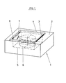
- This rotor 6 is covered in the room 5 on the one hand by the wall parts and the floor of the room and on the other hand by the cover 4.
- a cover lock 9 is provided at a distance from or opposite to the hinge 3, as will be described in the following is described in more detail.
- the lid 4 can be seen. It can be seen that lugs 10, 11 directed downward are arranged on the cover. For the lugs 10, 11 on the cover 4, two guide openings 47, 48 are arranged in the housing, which in particular hold the area 2 of the opening 15 together, so that the lug cannot expand when the bolt engages and is loaded.
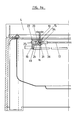
- the section 18 is designed in a special way with an engagement surface 24 which extends in the circumference and radial direction, into which a grub screw or projection 25 engages on the component 22, which is arranged in the housing, just like the other components 22, 23 which are practically guide blocks with the guide openings 20,21.
- Such engagement forms a propelling element for the rod or linkage, which forms the bolt 17.
- a rod or linkage is connected at its end remote from section 18 by a coupling 26 to a geared motor 27 which has a reduction gear.
- a motor 27 is mounted in lateral guides 28, 29 in a rotationally fixed but axially displaceable manner.
- the output shaft 30 is in axial alignment with the bolt 17, which is designed as a rotatable rod.
- cylindrical locking sections 36, 37 enter the openings 15 and thus hold the cover 4 in place.
- the cylindrical locking sections 36, 37 have a diameter which fits into the openings with very little play, one of which is designated by 15 in FIG.
- the engagement surface 24 is designed in the form of a spindle 45, which thus also forms the section 18.
- the motor 27 can move axially in its bearing.
- an axially displaceable coupling is arranged at 26, which permits torque transmission even when the engagement changes axially.
- a switch actuating means 38 is arranged as a thickened portion on the bolt 17 or on such a rod. It works depending on the setting of the linkage with one of the 39 or other 40 actuators of two limit switches 41, 42, which are arranged obliquely to the axis of the bolt 17 so that the actuators 39, 40 lie in the line of the bolt 17. As a result, the switch actuating means 38 can engage with one or the other actuating element 39, 40 for switching the motor 27.
- the distance between the actuators 39, 40 is such that a switch-off is always carried out when either the tapered sections 31, 32 their area of the lugs 10, 11 or the locking sections 36, 37 are arranged in the openings of the lugs 10, 11 , such an opening being drawn at 15 in FIG. 4.
- a spindle 51 has gear sections 52, 43 with a different pitch over its length, at the end of which there is still essentially a secure locking incline-free gear 44 is arranged.
- the passage sections 52, 43 form the engagement surface 46.
Landscapes
- Centrifugal Separators (AREA)
Priority Applications (1)
| Application Number | Priority Date | Filing Date | Title |
|---|---|---|---|
| AT9191112293T ATE105212T1 (de) | 1990-08-08 | 1991-07-23 | Deckelverriegelung fuer mittel- bis hochtourige laborzentrifugen. |
Applications Claiming Priority (2)
| Application Number | Priority Date | Filing Date | Title |
|---|---|---|---|
| DE4025134 | 1990-08-08 | ||
| DE4025134A DE4025134C1 (fr) | 1990-08-08 | 1990-08-08 |
Publications (3)
| Publication Number | Publication Date |
|---|---|
| EP0470428A2 true EP0470428A2 (fr) | 1992-02-12 |
| EP0470428A3 EP0470428A3 (en) | 1992-05-13 |
| EP0470428B1 EP0470428B1 (fr) | 1994-05-04 |
Family
ID=6411858
Family Applications (1)
| Application Number | Title | Priority Date | Filing Date |
|---|---|---|---|
| EP91112293A Expired - Lifetime EP0470428B1 (fr) | 1990-08-08 | 1991-07-23 | Dispositif de verrouillage de couvercle pour centrifuges de laboratoire, tournant à des vitesses moyennes ou élevées |
Country Status (6)
| Country | Link |
|---|---|
| US (1) | US5280975A (fr) |
| EP (1) | EP0470428B1 (fr) |
| JP (1) | JPH0647086B2 (fr) |
| AT (1) | ATE105212T1 (fr) |
| DE (2) | DE4025134C1 (fr) |
| ES (1) | ES2053247T3 (fr) |
Families Citing this family (22)
| Publication number | Priority date | Publication date | Assignee | Title |
|---|---|---|---|---|
| DE9417388U1 (de) * | 1994-10-29 | 1994-12-15 | Sigma Laborzentrifugen Gmbh, 37520 Osterode | Schließmechanismus für den Deckel einer Laborzentrifuge |
| DE19629361C1 (de) * | 1996-07-20 | 1997-11-20 | Heraeus Instr Gmbh | Schloß |
| DE29806972U1 (de) * | 1998-04-20 | 1999-05-20 | Andreas Hettich GmbH & Co. KG, 78532 Tuttlingen | Sicherheitsverschluß für Deckel |
| FR2790407B1 (fr) * | 1999-03-01 | 2001-06-01 | Jouan | Centrifugeuse a refroidissement par tube de ranque |
| FR2790406B1 (fr) * | 1999-03-01 | 2001-06-01 | Jouan | Centrifugeuse a entrainement pneumatique et a filtration de l'atmosphere de son enceinte |
| JP3879360B2 (ja) * | 2000-03-17 | 2007-02-14 | 日立工機株式会社 | 遠心機 |
| DE10017310B4 (de) * | 2000-04-10 | 2006-12-14 | Kendro Laboratory Products Gmbh | Verriegelung für einen um eine horizontale Achse schwenkbar angeordneten Gehäusedeckel einer Labor-Zentrifuge |
| DE10017314B4 (de) * | 2000-04-10 | 2005-02-24 | Kendro Laboratory Products Gmbh | Verriegelung für Gehäusedeckel von Laborgeräten |
| DE10164272C2 (de) * | 2001-12-27 | 2003-11-06 | Sigma Laborzentrifugen Gmbh | Verriegelungseinrichtung für den Deckel des Gehäuses einer Laborzentrifuge |
| JP4396528B2 (ja) * | 2005-01-11 | 2010-01-13 | 日立工機株式会社 | 遠心分離機 |
| JP2006198564A (ja) * | 2005-01-24 | 2006-08-03 | Hitachi Koki Co Ltd | 遠心分離機 |
| US7500942B2 (en) | 2005-01-24 | 2009-03-10 | Hitachi Koki Co, Ltd. | Centrifugal separator with door lock safety device |
| US7555933B2 (en) * | 2006-08-01 | 2009-07-07 | Thermo Fisher Scientific Inc. | Method and software for detecting vacuum concentrator ends-of-runs |
| DE102006041950A1 (de) * | 2006-08-30 | 2008-03-06 | Karl Storz Gmbh & Co.Kg | Stroboskopmodul mit einer Kupplung |
| JP4609443B2 (ja) * | 2007-02-28 | 2011-01-12 | 日立工機株式会社 | 遠心分離機 |
| JP4780044B2 (ja) * | 2007-06-11 | 2011-09-28 | 日立工機株式会社 | 遠心分離機 |
| DE102008010272B4 (de) | 2008-02-21 | 2013-08-22 | Thermo Electron Led Gmbh | Deckelverschluss für Gehäusedeckel von Laborgeräten und dergleichen |
| FR3005274B1 (fr) * | 2013-05-02 | 2015-05-01 | Afi Centrifuge | Centrifugeuse de laboratoire munie de moyens pour le verrouillage d'un couvercle dans sa position fermee |
| CN106345769B (zh) * | 2016-09-22 | 2018-05-08 | 四川杜伯特科技有限公司 | 一种舱门自动吸合装置 |
| DE102017128363A1 (de) * | 2017-11-30 | 2019-06-06 | Multivac Sepp Haggenmüller Se & Co. Kg | Verpackungsmaschine mit aufklappbarer schutzabdeckung |
| DE102019130524A1 (de) * | 2019-11-12 | 2021-05-12 | Andreas Hettich Gmbh & Co. Kg | Zentrifuge zur automatischen Beladung |
| EP4361385B1 (fr) * | 2022-10-25 | 2026-03-18 | Thermo Electron LED GmbH | Appareil pour verrouiller une porte d'appareil |
Family Cites Families (19)
| Publication number | Priority date | Publication date | Assignee | Title |
|---|---|---|---|---|
| US410807A (en) * | 1889-09-10 | Car-door fastener | ||
| DE132640C (fr) * | ||||
| US2587355A (en) * | 1948-01-15 | 1952-02-26 | Batesville Casket Company | Casket construction |
| US2787487A (en) * | 1955-01-21 | 1957-04-02 | L E Jones Corp | Casket closure device |
| US3439465A (en) * | 1965-10-20 | 1969-04-22 | Frank C Du Pre | Connector for joining the panels together edge to edge |
| US3633041A (en) * | 1970-07-20 | 1972-01-04 | Bio Consultants Inc | Centrifuge control system |
| DE2059318A1 (de) * | 1970-11-25 | 1972-05-31 | Bosch Siemens Hausgeraete | Waescheschleuder,insbesondere eine zum Schleudern eingerichtete Trommelwaschmaschine |
| US4012063A (en) * | 1975-11-26 | 1977-03-15 | Ametek, Inc. | Interlock latch assembly for centrifugals |
| US4019763A (en) * | 1976-01-21 | 1977-04-26 | E. I. Du Pont De Nemours And Company | Safety locking mechanism |
| US4105903A (en) * | 1976-12-13 | 1978-08-08 | American Home Products Corporation | Safety lid interlock circuit for centrifuges |
| SE422415B (sv) * | 1978-02-28 | 1982-03-08 | Rydborn S A O | Anordning for lasning av en platta i en oppning till en rotationskropp |
| DE2816395A1 (de) * | 1978-04-15 | 1979-10-25 | Heraeus Christ Gmbh | Zentrifuge mit deckelzuhaltung |
| DD154255A3 (de) * | 1980-08-29 | 1982-03-10 | Lothar Pomper | Deckelverschlusseinrichtung fuer schutzkessel von zentrifugen |
| US4345713A (en) * | 1981-04-13 | 1982-08-24 | Beckman Instruments, Inc. | Safety lock for air driven centrifuge |
| DD203921A1 (de) * | 1981-09-23 | 1983-11-09 | Waschgeraetewerk Veb | Sicherheitseinrichtung an rotierenden maschinen, wie zentrifugen oder trommelwaschmaschinen |
| FR2524346A1 (fr) * | 1982-04-06 | 1983-10-07 | Thomas Fils Sa Ets | Dispositif de verrouillage de couvercle, notamment pour machines tournantes telles que centrifugeuses |
| DE3872005T2 (de) * | 1987-03-20 | 1992-12-03 | Kubota Med Appliance Supply | Zentrifugalseparator. |
| DE3727168A1 (de) * | 1987-08-14 | 1989-02-23 | Steimel Gmbh & Co Maschinenfab | Zentrifugieranlage |
| DE3821840C1 (fr) * | 1988-06-29 | 1989-10-19 | Heraeus Sepatech Gmbh, 3360 Osterode, De |
-
1990
- 1990-08-08 DE DE4025134A patent/DE4025134C1/de not_active Expired - Lifetime
-
1991
- 1991-07-23 EP EP91112293A patent/EP0470428B1/fr not_active Expired - Lifetime
- 1991-07-23 AT AT9191112293T patent/ATE105212T1/de not_active IP Right Cessation
- 1991-07-23 DE DE59101553T patent/DE59101553D1/de not_active Expired - Fee Related
- 1991-07-23 ES ES91112293T patent/ES2053247T3/es not_active Expired - Lifetime
- 1991-08-07 JP JP3223358A patent/JPH0647086B2/ja not_active Expired - Fee Related
- 1991-08-08 US US07/742,132 patent/US5280975A/en not_active Expired - Fee Related
Also Published As
| Publication number | Publication date |
|---|---|
| EP0470428A3 (en) | 1992-05-13 |
| ES2053247T3 (es) | 1994-07-16 |
| JPH04227079A (ja) | 1992-08-17 |
| JPH0647086B2 (ja) | 1994-06-22 |
| ATE105212T1 (de) | 1994-05-15 |
| DE4025134C1 (fr) | 1991-11-14 |
| US5280975A (en) | 1994-01-25 |
| DE59101553D1 (de) | 1994-06-09 |
| EP0470428B1 (fr) | 1994-05-04 |
Similar Documents
| Publication | Publication Date | Title |
|---|---|---|
| EP0470428B1 (fr) | Dispositif de verrouillage de couvercle pour centrifuges de laboratoire, tournant à des vitesses moyennes ou élevées | |
| DE69902944T2 (de) | Befestigungsvorrichtung zum schnellen an- bzw. abkoppeln eines bauteils an eine bzw. von einer auflagefläche | |
| DE69412880T2 (de) | Drehbetätigungseinrichtung für einen Leistungsschalter | |
| DE3605821C2 (fr) | ||
| EP0406645B1 (fr) | Dispositif pour le guidage individuel de boulons ou pointes disposés les uns derrière les autres entre des rails de guidage | |
| EP1167755A2 (fr) | Dispositif de blocage pour le rotor d'une éolienne | |
| DE3421452A1 (de) | Vorrichtung zum automatischen erfassen bzw. loesen eines werkzeugtraegers bei einem manipulator | |
| DE102007053452A1 (de) | Antriebseinrichtung | |
| DE60318568T2 (de) | Elektrischer Stellantrieb für Schwenktüren und dgl. | |
| EP1281110A1 (fr) | Dispositif d'actionnement | |
| DE2914844C2 (de) | Schnellspannvorrichtung, insbesondere für Auswuchtmaschinen zum Auswuchten von Fahrzeugrädern | |
| EP0555633B1 (fr) | Garniture pour poignée de porte | |
| DE2905363C2 (de) | Scherbolzenkupplung | |
| EP3957813B1 (fr) | Dispositif d'entraînement et porte coulissante | |
| EP3408477B1 (fr) | Serrure à pêne pivotant | |
| DE2651693A1 (de) | Zahnradsicherung | |
| DE3603461A1 (de) | Arretiervorrichtung fuer eine werkzeugmaschine, insbesondere eine elektrische handwerkzeugmaschine | |
| DE3941935C2 (de) | Spannschloß | |
| DE19906268A1 (de) | Vorrichtung zur elektrischen Verriegelung der Lenkspindel einer Lenkeinrichtung | |
| CH669636A5 (fr) | ||
| DE19607765A1 (de) | Vorrichtung zum Betätigen eines Schlosses, insbesondere eines über eine Kontrolleinrichtung zu sichernden Schlosses | |
| DE9402338U1 (de) | Fahr-Brems-Steuerschalter für elektrisch angetriebene Schienenfahrzeuge | |
| DE102005058176A1 (de) | Verriegelungseinrichtung für eine Überlagerungsvorrichtung und Überlagerungsvorrichtung für ein Lenksystem | |
| DE3203956C2 (de) | Sprungantriebsvorrichtung für ein elektrisches Schaltgerät | |
| DE2831514C2 (de) | Mehrkantiger Wechselschloßstift |
Legal Events
| Date | Code | Title | Description |
|---|---|---|---|
| PUAI | Public reference made under article 153(3) epc to a published international application that has entered the european phase |
Free format text: ORIGINAL CODE: 0009012 |
|
| AK | Designated contracting states |
Kind code of ref document: A2 Designated state(s): AT BE CH DE ES FR GB IT LI LU NL SE |
|
| PUAL | Search report despatched |
Free format text: ORIGINAL CODE: 0009013 |
|
| AK | Designated contracting states |
Kind code of ref document: A3 Designated state(s): AT BE CH DE ES FR GB IT LI LU NL SE |
|
| 17P | Request for examination filed |
Effective date: 19920527 |
|
| 17Q | First examination report despatched |
Effective date: 19930915 |
|
| GRAA | (expected) grant |
Free format text: ORIGINAL CODE: 0009210 |
|
| AK | Designated contracting states |
Kind code of ref document: B1 Designated state(s): AT BE CH DE ES FR GB IT LI LU NL SE |
|
| REF | Corresponds to: |
Ref document number: 105212 Country of ref document: AT Date of ref document: 19940515 Kind code of ref document: T |
|
| REF | Corresponds to: |
Ref document number: 59101553 Country of ref document: DE Date of ref document: 19940609 |
|
| REG | Reference to a national code |
Ref country code: ES Ref legal event code: FG2A Ref document number: 2053247 Country of ref document: ES Kind code of ref document: T3 |
|
| EPTA | Lu: last paid annual fee | ||
| ITF | It: translation for a ep patent filed | ||
| GBT | Gb: translation of ep patent filed (gb section 77(6)(a)/1977) |
Effective date: 19940712 |
|
| ET | Fr: translation filed | ||
| EAL | Se: european patent in force in sweden |
Ref document number: 91112293.5 |
|
| PLBE | No opposition filed within time limit |
Free format text: ORIGINAL CODE: 0009261 |
|
| STAA | Information on the status of an ep patent application or granted ep patent |
Free format text: STATUS: NO OPPOSITION FILED WITHIN TIME LIMIT |
|
| 26N | No opposition filed | ||
| REG | Reference to a national code |
Ref country code: CH Ref legal event code: PFA Free format text: EPPENDORF-NETHELER-HINZ GMBH TRANSFER- EPPENDORF AG |
|
| REG | Reference to a national code |
Ref country code: FR Ref legal event code: CJ Ref country code: FR Ref legal event code: CD |
|
| NLS | Nl: assignments of ep-patents |
Owner name: EPPENDORF AG |
|
| REG | Reference to a national code |
Ref country code: GB Ref legal event code: IF02 |
|
| PGFP | Annual fee paid to national office [announced via postgrant information from national office to epo] |
Ref country code: AT Payment date: 20020606 Year of fee payment: 12 |
|
| PGFP | Annual fee paid to national office [announced via postgrant information from national office to epo] |
Ref country code: FR Payment date: 20020610 Year of fee payment: 12 |
|
| PGFP | Annual fee paid to national office [announced via postgrant information from national office to epo] |
Ref country code: GB Payment date: 20020612 Year of fee payment: 12 |
|
| PGFP | Annual fee paid to national office [announced via postgrant information from national office to epo] |
Ref country code: SE Payment date: 20020617 Year of fee payment: 12 Ref country code: CH Payment date: 20020617 Year of fee payment: 12 |
|
| PGFP | Annual fee paid to national office [announced via postgrant information from national office to epo] |
Ref country code: NL Payment date: 20020619 Year of fee payment: 12 Ref country code: DE Payment date: 20020619 Year of fee payment: 12 |
|
| PGFP | Annual fee paid to national office [announced via postgrant information from national office to epo] |
Ref country code: ES Payment date: 20020704 Year of fee payment: 12 |
|
| PGFP | Annual fee paid to national office [announced via postgrant information from national office to epo] |
Ref country code: LU Payment date: 20020715 Year of fee payment: 12 |
|
| PGFP | Annual fee paid to national office [announced via postgrant information from national office to epo] |
Ref country code: BE Payment date: 20020724 Year of fee payment: 12 |
|
| PG25 | Lapsed in a contracting state [announced via postgrant information from national office to epo] |
Ref country code: LU Free format text: LAPSE BECAUSE OF NON-PAYMENT OF DUE FEES Effective date: 20030723 Ref country code: GB Free format text: LAPSE BECAUSE OF NON-PAYMENT OF DUE FEES Effective date: 20030723 Ref country code: AT Free format text: LAPSE BECAUSE OF NON-PAYMENT OF DUE FEES Effective date: 20030723 |
|
| PG25 | Lapsed in a contracting state [announced via postgrant information from national office to epo] |
Ref country code: SE Free format text: LAPSE BECAUSE OF NON-PAYMENT OF DUE FEES Effective date: 20030724 Ref country code: ES Free format text: LAPSE BECAUSE OF NON-PAYMENT OF DUE FEES Effective date: 20030724 |
|
| PG25 | Lapsed in a contracting state [announced via postgrant information from national office to epo] |
Ref country code: LI Free format text: LAPSE BECAUSE OF NON-PAYMENT OF DUE FEES Effective date: 20030731 Ref country code: CH Free format text: LAPSE BECAUSE OF NON-PAYMENT OF DUE FEES Effective date: 20030731 Ref country code: BE Free format text: LAPSE BECAUSE OF NON-PAYMENT OF DUE FEES Effective date: 20030731 |
|
| BERE | Be: lapsed |
Owner name: *EPPENDORF A.G. Effective date: 20030731 |
|
| PG25 | Lapsed in a contracting state [announced via postgrant information from national office to epo] |
Ref country code: NL Free format text: LAPSE BECAUSE OF NON-PAYMENT OF DUE FEES Effective date: 20040201 |
|
| PG25 | Lapsed in a contracting state [announced via postgrant information from national office to epo] |
Ref country code: DE Free format text: LAPSE BECAUSE OF NON-PAYMENT OF DUE FEES Effective date: 20040203 |
|
| EUG | Se: european patent has lapsed | ||
| REG | Reference to a national code |
Ref country code: CH Ref legal event code: PL |
|
| GBPC | Gb: european patent ceased through non-payment of renewal fee |
Effective date: 20030723 |
|
| PG25 | Lapsed in a contracting state [announced via postgrant information from national office to epo] |
Ref country code: FR Free format text: LAPSE BECAUSE OF NON-PAYMENT OF DUE FEES Effective date: 20040331 |
|
| NLV4 | Nl: lapsed or anulled due to non-payment of the annual fee |
Effective date: 20040201 |
|
| REG | Reference to a national code |
Ref country code: FR Ref legal event code: ST |
|
| REG | Reference to a national code |
Ref country code: ES Ref legal event code: FD2A Effective date: 20030724 |
|
| PG25 | Lapsed in a contracting state [announced via postgrant information from national office to epo] |
Ref country code: IT Free format text: LAPSE BECAUSE OF NON-PAYMENT OF DUE FEES;WARNING: LAPSES OF ITALIAN PATENTS WITH EFFECTIVE DATE BEFORE 2007 MAY HAVE OCCURRED AT ANY TIME BEFORE 2007. THE CORRECT EFFECTIVE DATE MAY BE DIFFERENT FROM THE ONE RECORDED. Effective date: 20050723 |