EP0470558B1 - Positionsmessvorrichtung - Google Patents
Positionsmessvorrichtung Download PDFInfo
- Publication number
- EP0470558B1 EP0470558B1 EP19910113143 EP91113143A EP0470558B1 EP 0470558 B1 EP0470558 B1 EP 0470558B1 EP 19910113143 EP19910113143 EP 19910113143 EP 91113143 A EP91113143 A EP 91113143A EP 0470558 B1 EP0470558 B1 EP 0470558B1
- Authority
- EP
- European Patent Office
- Prior art keywords
- signal
- excitation
- signals
- transducer
- excitation signal
- Prior art date
- Legal status (The legal status is an assumption and is not a legal conclusion. Google has not performed a legal analysis and makes no representation as to the accuracy of the status listed.)
- Expired - Lifetime
Links
- 238000005259 measurement Methods 0.000 title claims description 8
- 230000005284 excitation Effects 0.000 claims description 60
- 230000008878 coupling Effects 0.000 claims description 16
- 238000010168 coupling process Methods 0.000 claims description 16
- 238000005859 coupling reaction Methods 0.000 claims description 16
- 238000004804 winding Methods 0.000 claims description 4
- 238000000034 method Methods 0.000 description 8
- 239000004020 conductor Substances 0.000 description 7
- 230000000694 effects Effects 0.000 description 6
- 230000009467 reduction Effects 0.000 description 4
- 230000010363 phase shift Effects 0.000 description 3
- 230000008030 elimination Effects 0.000 description 2
- 238000003379 elimination reaction Methods 0.000 description 2
- 230000004044 response Effects 0.000 description 2
- XPRGFWCOARUGAL-UHFFFAOYSA-N 3-anilino-1-phenylpyrrolidine-2,5-dione Chemical compound O=C1N(C=2C=CC=CC=2)C(=O)CC1NC1=CC=CC=C1 XPRGFWCOARUGAL-UHFFFAOYSA-N 0.000 description 1
- 239000003990 capacitor Substances 0.000 description 1
- 238000006243 chemical reaction Methods 0.000 description 1
- 230000002301 combined effect Effects 0.000 description 1
- 125000004122 cyclic group Chemical group 0.000 description 1
- 230000001939 inductive effect Effects 0.000 description 1
- 238000009434 installation Methods 0.000 description 1
- 239000000463 material Substances 0.000 description 1
- 230000010355 oscillation Effects 0.000 description 1
- 230000008569 process Effects 0.000 description 1
Images


Classifications
-
- G—PHYSICS
- G08—SIGNALLING
- G08C—TRANSMISSION SYSTEMS FOR MEASURED VALUES, CONTROL OR SIMILAR SIGNALS
- G08C19/00—Electric signal transmission systems
- G08C19/38—Electric signal transmission systems using dynamo-electric devices
- G08C19/46—Electric signal transmission systems using dynamo-electric devices of which both rotor and stator carry windings
Definitions
- This invention relates generally to apparatus for position measurement.
- this invention relates to interface circuits used with electromagnetic position transducers.
- Position transducers which are of interest herein include resolvers and slider and scale systems producing AC output signals in response to AC excitation signals wherein a phase shift between the excitation signals and the output signals is introduced by the relative position of a transducer armature and stator. The position of the armature relative to the stator is measured by detecting this phase difference.
- phase discrimination technique wherein the excitation signals are applied to pairs of windings arranged in quadrature, and the position induced phase shift is detected by phase comparison of the output signal with a reference from which the excitation signals are derived
- amplitude technique wherein the output signals are produced by the quadrature windings and the position induced phase shift is detected from the ratio of the instantaneous magnitudes of the output signals.
- Fig. 1a illustrates an arrangement used with the amplitude technique employing a resolver to measure position of a moveable member of, for example, machine tools, robots or other position controlled equipment.
- the resolver 10 includes a rotor 12 having an armature coil 14, and a stator having stator coils 16 and 18.
- the rotor 12 is rotated relative to the stator by, for example, a motor 28.
- the transducer 10 is located remotely from a control device 20 wherein a drive amplifier 22 produces an AC excitation signal applied to the armature coil 14. Output signals appearing at the stator coils 16 and 18 are returned to differential amplifiers 24 and 26 located in control 20.
- Conducting cables 30, 32, and 34 typically twisted pairs, provide connection of excitation and output signals between the interface circuits of control 20 and the resolver 10.
- Fig. 1b illustrates an arrangement used with the phase discrimination technique employing a resolver to measure position of a moveable member.
- excitation signals are produced by drive amplifiers 23 and 25 and applied to the resolver stator coils 17 and 19.
- An output signal appears at resolver armature coil 13 and is returned to differential amplifier 21 in control 19.
- the excitation signals are derived from a single reference signal and are phased displaced one from the other by ⁇ /2 radians.
- Fig. 2 illustrates capacitive coupling between an excitation signal cable and an output signal cable which will exist as a result of proximity of the conducting cables 30, 32 and 34 of Fig. la or cables 29, 36 and 38 of Fig. 1b.
- capacitors C1, C2, C3, and C4 represent lumped values of the coupling capacitances distributed over the lengths of the conducting cables; source SD represents the source of excitation signals; and, load LD represents the load impedance presented to an output signal.
- Inductive coupling of the rotor and stator windings is intentionally omitted to simplify the analysis of the capacitive coupling in the conducting cables. It will be appreciated from Fig. 2 that by virtue of the grounded return paths only capacitance C1 contributes an error component to the output signal appearing across the load.
- the voltage error component in the output signals arising from capacitive coupling as shown in Fig. 2 has a magnitude equal to the excitation signal magnitude and is phase displaced ⁇ /2 radians therefrom.
- the current due to this error component is added algebraically to the output signal current magnitude, resulting in a position error repeated over the range of position measured by the resolver.
- Such errors are referred to as "cyclic errors.” It is common practice to provide individual shields for each conducting cable, such as shields 31, 33, and 35 to reduce or eliminate capacitive coupling between the excitation and output signal cables. The cost of such shielding significantly increases the material and labor costs associated with the installation of such cables.
- the present invention provides an excitation signal source for use with electromagnetic position transducers producing an AC excitation signal symmetrical with respect to ground.
- a first AC signal is inverted to produce a second AC signal and the excitation signal is taken as the difference between the first and second AC signals.
- a receiver for use with electromagnetic position transducers is provided having matched impedances for signal and return lines of an output signal.
- Figs. 1a and 1b illustrate prior art circuits for position measurement using a resolver.
- Fig 2 illustrates capacitive coupling between excitation and output signal conducting cables.
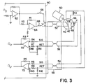
- Fig. 3 illustrates circuits of the present invention as applied to a resolver.
- Figs. 4a, 4b and 4c are equivalent circuits illustrating the effects of the circuits of Fig. 3 on the capacitive coupling illustrated by Fig. 2.
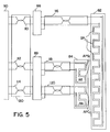
- Fig 5 illustrates circuits of the present invention as applied to a slider and scale system.
- electromagnetic position transducer interface circuits of a motor control device developed for Cincinnati Milacron Inc., the assignee of the present invention shall be described in detail. While the interface circuits to be described constitute a preferred embodiment, it is not the intention of applicants to limit the scope of the invention to the details thereof.
- a resolver 40 mechanically coupled to motor 50, is shown remotely located from motor controller 60. None of the details of motor controller 60 pertaining to control of motor 50 are pertinent to the present invention and these details shall not be described herein.
- Motor 50 under control of controller 60, effects rotation of rotor 42 relative to a resolver stator.
- Stator coils 46 and 48 are fixed relative to the resolver stator and produce AC output signals in response to an AC excitation signal impressed on rotor coil 44.
- the output signals F1 and F2 are expressed as functions of the excitation signal and the relative angular position of the rotor 42 and stator as follows:
- F1 E * sine( ⁇ ) * sine(Wt)
- F2 E * cosine ( ⁇ ) * sine(Wt)
- the excitation signal may in fact be inductively coupled thereto from the stator in brushless resolvers.
- the signal and return paths of the excitation signal are provided by twisted pair conductor cable 52.
- the signal and return paths for the output signals F1 and F2 are provided in, respectively, twisted pair conductor cables 54 and 56.
- the excitation signal V1 is taken across the outputs of amplifiers 62 and 64.
- Amplifier 62 receives a sinusoidal AC signal S1 of constant frequency W derived from a square wave.
- the output of amplifier 62 is inverted by amplifier 64.
- Series inductors 66 and 68 are provided to reduce the possibility of high frequency oscillation appearing at the outputs of amplifiers 62 and 64 when connected to cables presenting relatively high capacitive loads.
- Gain setting resistors R1 and R2 are of equal value within a moderately close tolerance as may be readily achieved, for example, using 1% components.
- the excitation signal V1 is symmetrical about ground due to the inversion of the output of amplifier 62 by amplifier 64.
- output signals F1 and F2 are received by differential amplifiers 70 and 72 which amplify the potential difference appearing across the signal and return paths of the twisted pair conductor cables 56 and 54.
- the use of differential amplifiers provides high rejection of noise signals common to the amplifier inputs.
- Gain determining components R4, R7, and R6, R9 are chosen to have equal values within a component tolerance of 0.1% to facilitate analogue to digital conversion with an accuracy of 12 binary digits.
- Gain determining components R8 and R3 of amplifier 70 and resistors R10 and R5 of amplifier 72 are also chosen to be equal within a component tolerance of 0.1%.
- impedance matching resistors R11 and R12 are connected between the return path input and ground at respectively, amplifier 70 and amplifier 72.
- the resistor R11 has a value equal to half the product of the sum of the values of resistors R7 and R8 multiplied by the ratio of R7 to R8 and the resistor R12 has a value equal to half the product of the sum of the values of resistors R9 and R10 and the ratio of R9 to R10.
- Fig. 5 shows the use of a symmetrical excitation signal and balanced impedance receivers for the output signals as applied to a slider and scale measuring system 80.
- a scale excitation signal output by scale amplifier 88 is applied to a scale 82.
- Scale 82 has a formed conductor defining pole segments SP I having a pitch I.
- Slider output signals are induced in slider formed conductors 85 and 86 by the scale excitation signal.
- the slider formed conductors 85 and 86 define pole segments APS I and APC I having the same pitch I as the scale pole segments.
- the slider pole segments are arranged relative to one another so as to be spatially separated by I/4.
- the slider output signals are transmitted to line amplifiers 89 proximate the slider 84 via conducting cables 118 and 120.
- Line amplifiers 89 produce AC output signals which are transmitted to control 90 via conducting cables 112 and 114.
- An excitation signal generated at control 90 is transmitted to scale amplifier 88 proximate the scale 82 via conducting cable 110.
- Scale amplifier 88 produces the scale excitation signal conducted by cable 116 to scale 82.
- Relative position of the slider 84 and scale 82 may be determined from the slider output signals using the amplitude technique described for use with resolvers. Because of the low impedance of the interface between the slider and scale system and of the amplifiers 88 and 89, capacitive coupling between the scale excitation signal and the slider output signals does not generally give rise to an appreciable error component in the measured position. Conversely, the interface between the control 90 and the amplifiers 88 and 89 is susceptible to the same capacitive effects discussed with reference to Fig. 2. Therefor, the use of an excitation signal symmetrical with respect to ground and matched impedances in the signal and return lines of the output signals provide the same advantages as previously discussed thereby permitting the inclusion of cables 110, 112 and 114 within a single shield 130.
- the circuits of control 90 used in this application are the same as shown in Fig. 3.
Landscapes
- Physics & Mathematics (AREA)
- General Physics & Mathematics (AREA)
- Transmission And Conversion Of Sensor Element Output (AREA)
- Arrangements For Transmission Of Measured Signals (AREA)
- Measurement Of Length, Angles, Or The Like Using Electric Or Magnetic Means (AREA)
Claims (5)
- Vorrichtung zur Positionsmessung, wobei leitende Kabel (52, 54, 56) Wechselspannungs-Erregungssignale und Wechselspannungs-Wandlerausgangssignale zwischen einem elektromagnetischen Positionswandler (40) und zugehörigen Schnittstellenschaltkreisen (60), die von diesem entfernt sind, führen, wobei die Schnittstellenschaltkreise Mittel zum Erzeugen eines Erregungssignals und Empfänger zum Aufnehmen der Ausgangssignale des Wandlers aufweisen, wobei die Vorrichtung charakterisiert ist durch eine Verschaltung des Signals und des Rückflusses zum Reduzieren der effektiven Kopplungskapazität (C1, C2, C32, C4) zwischen den leitenden Kabeln, wobei die Schaltung Mittel zum Erzeugen des Erregungssignals mit einem Verstärker (62) zum Erzeugen eines ersten Wechselspannungssignals, Mittel (64) zum Invertieren des ersten Wechselspannungs-Signals zum Erzeugen eines zweiten Wechselspannungs-Signals in Gegenphase relativ zu dem ersten Wechselspannungs-Signal aufweist und das Erregungssignal als die Potentialdifferenz zwischen dem ersten Wechselspannungs-Signal und dem zweiten Wechselspannungs-Signal genommen wird.
- Die Vorrichtung von Anspruch 1, weiter gekennzeichnet durch Empfänger für das Ausgangssignal mit Signalempfangsmitteln (70, R3, R4, R7, R8, R11; 72, R5, R6, R9, R10, R12), die einen Signal- und Rückflußweg für die Ausgangssignale (F1, F2) des Wandlers bilden, bei denen die Impedanz des Signal- und Rückflußweges zur Masse gleich sind.
- Vorrichtung zur Positionsmessung, wobei leitende Kabel (52, 50) Wechselspannungs-Erregungssignale und Wechselspannungs-Wandlerausgangssignale zwischen einem elektromagnetischen Positionswandler (40) und zugehörigen Schnittstellenschaltungen (60), die von diesem entfernt sind, führen, die Schnittstellenschaltungen Mittel zum Erzeugen eines Erregungssignals und Empfänger zum Empfangen eines Wandlerausgangs-Signals aufweisen, und die Vorrichtung gekennzeichnet ist durch eine Signal- und Rückf lußverschaltung zum Verringern der effektiven Kopplungskapazität (C1, C2, C2, C4) zwischen den leitenden Kabeln, wobei die Verschaltung Empfangsmittel (70, R3, R4, R7, R8, R11; 72, R5, R6, R9, R10, R12) für das Wandlerausgangs-Signal aufweist, das Signal- und Rückführungswege für die Wandlerausgangs-Signale (F1, F2) schafft, bei denen die Impedanzen des Signalwegs und des Rückflußweges zur Masse gleich sind.
- Die Vorrichtung nach Anspruch 3, dadurch gekennzeichnet, daß das das Erregungssignal erzeugende Mittel einen ersten Verstärker (62) zum Erzeugen eines ersten Wechselspannungs-Signals und einen zweiten Verstärker (64) zum Invertieren des ersten Wechselspannungs-Signals zum Erzeugen eines zweiten Wechselspannungs-Signals, das gegenüber dem ersten Wechselspannungs-Signal gegenphasig ist, aufweist, wobei das Erregungssignal als die Potentialdifferenz zwischen dem ersten Wechselspannungs-Signal und dem zweiten Wechselspannungs-Signal genommen wird.
- Vorrichtung nach einem der vorangehenden Ansprüche, weiter dadurch gekennzeichnet, daß der Wandler ein Drehmelder mit einem Rotor (42) mit einer Rotorspule (44) und Statorwicklungen (46, 48) zum Auflösen von Wechselspannungs-Erregungssignale in ein erstes Wechselspannungs-Ausgangssignal in der Form E * sin (ϑ * sin (Wt) und ein zweites Wechselspannungs-Ausgangssignal in der Form E * cos (ϑ) * sin (Wt) ist, wobei E die Größe des Erregungssignals, ϑ die relative Winkelposition des Stators und des Ankers, W die Frequenz des Erregungssignals und t die Zeit angibt.
Applications Claiming Priority (2)
| Application Number | Priority Date | Filing Date | Title |
|---|---|---|---|
| US58348090A | 1990-08-06 | 1990-08-06 | |
| US583480 | 1990-08-06 |
Publications (3)
| Publication Number | Publication Date |
|---|---|
| EP0470558A2 EP0470558A2 (de) | 1992-02-12 |
| EP0470558A3 EP0470558A3 (en) | 1992-05-27 |
| EP0470558B1 true EP0470558B1 (de) | 1995-10-18 |
Family
ID=24333280
Family Applications (1)
| Application Number | Title | Priority Date | Filing Date |
|---|---|---|---|
| EP19910113143 Expired - Lifetime EP0470558B1 (de) | 1990-08-06 | 1991-08-05 | Positionsmessvorrichtung |
Country Status (4)
| Country | Link |
|---|---|
| EP (1) | EP0470558B1 (de) |
| JP (1) | JPH04233699A (de) |
| CA (1) | CA2048382C (de) |
| DE (1) | DE69113916T2 (de) |
Families Citing this family (1)
| Publication number | Priority date | Publication date | Assignee | Title |
|---|---|---|---|---|
| CN106092150B (zh) * | 2016-06-01 | 2018-07-03 | 同济大学 | 旋转变压器的位置信息获取方法、系统及电子设备 |
Family Cites Families (3)
| Publication number | Priority date | Publication date | Assignee | Title |
|---|---|---|---|---|
| US4207505A (en) * | 1977-05-09 | 1980-06-10 | Sundstrand Corporation | Measuring system |
| US4270061A (en) * | 1978-11-03 | 1981-05-26 | The Singer Company | Current transformer input system for AC conversion devices |
| US4270077A (en) * | 1980-03-10 | 1981-05-26 | Sperry Corporation | Demodulatorless synchro position sensor apparatus utilizing square wave excitation |
-
1991
- 1991-08-02 CA CA 2048382 patent/CA2048382C/en not_active Expired - Fee Related
- 1991-08-05 EP EP19910113143 patent/EP0470558B1/de not_active Expired - Lifetime
- 1991-08-05 DE DE1991613916 patent/DE69113916T2/de not_active Expired - Lifetime
- 1991-08-06 JP JP19665991A patent/JPH04233699A/ja active Pending
Also Published As
| Publication number | Publication date |
|---|---|
| EP0470558A2 (de) | 1992-02-12 |
| DE69113916T2 (de) | 1996-04-04 |
| CA2048382A1 (en) | 1992-02-07 |
| CA2048382C (en) | 1997-01-14 |
| DE69113916D1 (de) | 1995-11-23 |
| EP0470558A3 (en) | 1992-05-27 |
| JPH04233699A (ja) | 1992-08-21 |
Similar Documents
| Publication | Publication Date | Title |
|---|---|---|
| US4091322A (en) | Eddy current generating type metal pipeline detector | |
| EP0308656B1 (de) | Verfahren und Vorrichtung zum Erzeugen eines digitalen Signales, das eine Winkelverschiebung anzeigt | |
| US5525900A (en) | Method for determining the displacement of an object of an electrically conducting material | |
| GB1582002A (en) | Method of and apparatus for fault-location on electrical transmission lines | |
| Szymczak et al. | Precision resolver-to-digital converter measures angular position and velocity | |
| EP1099096A1 (de) | Kapazitiver positionssensor | |
| US3696518A (en) | Vehicle direction sensing and steering systems using magnetic flux responsive means | |
| US4268786A (en) | Position pickup for numerically controlled machine tools | |
| EP0470558B1 (de) | Positionsmessvorrichtung | |
| JP3309027B2 (ja) | リラクタンスレゾルバ | |
| US5164720A (en) | Interface circuits for electromagnetic position transducers | |
| US8198888B2 (en) | Method and system for determining the distance between a profiled surface and a functional surface moving in relation thereto by using measurement coils and a reference coil | |
| JPH0933204A (ja) | 導電性リアクションレールとそれに対して相対的に動く機能面との間隔を確実に測定する測定方法及びこの方法に適したセンサ | |
| CA2255975C (en) | Measuring circuit | |
| EP0184860B1 (de) | Vorrichtung zum Bilden eines wechselnden Signals | |
| US4461987A (en) | Current sensing circuit for motor controls | |
| US3139572A (en) | Means for increasing the accuracy of synchros or the like | |
| SU1742996A1 (ru) | Преобразователь угла поворота вала в код | |
| EP0159786B1 (de) | Messung von Impedanzverhältnissen | |
| Datlinger et al. | Holistic consideration and optimization of signal processing on a resolver-based rotor position sensor systems in electric drive trains | |
| EP4707745A1 (de) | Induktiver positionssensor | |
| RU2153650C2 (ru) | Способ выделения сигналов дифференциального датчика | |
| RU2066043C1 (ru) | Тензопреобразователь | |
| JP2947097B2 (ja) | 伝送ケーブル | |
| SU1185063A1 (ru) | Индуктивное измерительное устройство |
Legal Events
| Date | Code | Title | Description |
|---|---|---|---|
| PUAI | Public reference made under article 153(3) epc to a published international application that has entered the european phase |
Free format text: ORIGINAL CODE: 0009012 |
|
| AK | Designated contracting states |
Kind code of ref document: A2 Designated state(s): DE FR GB IT |
|
| PUAL | Search report despatched |
Free format text: ORIGINAL CODE: 0009013 |
|
| AK | Designated contracting states |
Kind code of ref document: A3 Designated state(s): DE FR GB IT |
|
| 17P | Request for examination filed |
Effective date: 19920918 |
|
| 17Q | First examination report despatched |
Effective date: 19940311 |
|
| GRAA | (expected) grant |
Free format text: ORIGINAL CODE: 0009210 |
|
| AK | Designated contracting states |
Kind code of ref document: B1 Designated state(s): DE FR GB IT |
|
| PG25 | Lapsed in a contracting state [announced via postgrant information from national office to epo] |
Ref country code: IT Free format text: LAPSE BECAUSE OF FAILURE TO SUBMIT A TRANSLATION OF THE DESCRIPTION OR TO PAY THE FEE WITHIN THE PRE;WARNING: LAPSES OF ITALIAN PATENTS WITH EFFECTIVE DATE BEFORE 2007 MAY HAVE OCCURRED AT ANY TIME BEFORE 2007. THE CORRECT EFFECTIVE DATE MAY BE DIFFERENT FROM THE ONE RECORDED.SCRIBED TIME-LIMIT Effective date: 19951018 Ref country code: FR Effective date: 19951018 |
|
| REF | Corresponds to: |
Ref document number: 69113916 Country of ref document: DE Date of ref document: 19951123 |
|
| EN | Fr: translation not filed | ||
| PLBE | No opposition filed within time limit |
Free format text: ORIGINAL CODE: 0009261 |
|
| STAA | Information on the status of an ep patent application or granted ep patent |
Free format text: STATUS: NO OPPOSITION FILED WITHIN TIME LIMIT |
|
| 26N | No opposition filed | ||
| REG | Reference to a national code |
Ref country code: GB Ref legal event code: IF02 |
|
| PGFP | Annual fee paid to national office [announced via postgrant information from national office to epo] |
Ref country code: GB Payment date: 20100812 Year of fee payment: 20 |
|
| PGFP | Annual fee paid to national office [announced via postgrant information from national office to epo] |
Ref country code: DE Payment date: 20101018 Year of fee payment: 20 |
|
| REG | Reference to a national code |
Ref country code: DE Ref legal event code: R071 Ref document number: 69113916 Country of ref document: DE |
|
| REG | Reference to a national code |
Ref country code: DE Ref legal event code: R071 Ref document number: 69113916 Country of ref document: DE |
|
| REG | Reference to a national code |
Ref country code: GB Ref legal event code: PE20 Expiry date: 20110804 |
|
| PG25 | Lapsed in a contracting state [announced via postgrant information from national office to epo] |
Ref country code: GB Free format text: LAPSE BECAUSE OF EXPIRATION OF PROTECTION Effective date: 20110804 |
|
| PG25 | Lapsed in a contracting state [announced via postgrant information from national office to epo] |
Ref country code: DE Free format text: LAPSE BECAUSE OF EXPIRATION OF PROTECTION Effective date: 20110806 |