EP0470562A1 - Vorrichtung zum Färben von Garnspulen - Google Patents
Vorrichtung zum Färben von Garnspulen Download PDFInfo
- Publication number
- EP0470562A1 EP0470562A1 EP91113156A EP91113156A EP0470562A1 EP 0470562 A1 EP0470562 A1 EP 0470562A1 EP 91113156 A EP91113156 A EP 91113156A EP 91113156 A EP91113156 A EP 91113156A EP 0470562 A1 EP0470562 A1 EP 0470562A1
- Authority
- EP
- European Patent Office
- Prior art keywords
- holder
- drum
- reels
- holders
- chamber
- Prior art date
- Legal status (The legal status is an assumption and is not a legal conclusion. Google has not performed a legal analysis and makes no representation as to the accuracy of the status listed.)
- Withdrawn
Links
- 238000004043 dyeing Methods 0.000 title claims abstract description 28
- 238000001035 drying Methods 0.000 claims description 12
- 239000000463 material Substances 0.000 claims description 11
- 238000005192 partition Methods 0.000 claims description 6
- 230000002441 reversible effect Effects 0.000 claims description 5
- 125000006850 spacer group Chemical group 0.000 claims description 5
- 239000012530 fluid Substances 0.000 claims description 2
- 239000007788 liquid Substances 0.000 claims description 2
- 239000002184 metal Substances 0.000 claims description 2
- 239000000975 dye Substances 0.000 description 8
- 241000196324 Embryophyta Species 0.000 description 2
- 230000001133 acceleration Effects 0.000 description 2
- 238000004519 manufacturing process Methods 0.000 description 2
- 238000000034 method Methods 0.000 description 2
- 238000011282 treatment Methods 0.000 description 2
- 240000002129 Malva sylvestris Species 0.000 description 1
- 235000006770 Malva sylvestris Nutrition 0.000 description 1
- 238000004873 anchoring Methods 0.000 description 1
- 230000005540 biological transmission Effects 0.000 description 1
- 238000004061 bleaching Methods 0.000 description 1
- 235000013351 cheese Nutrition 0.000 description 1
- 238000010276 construction Methods 0.000 description 1
- 238000001816 cooling Methods 0.000 description 1
- 230000005484 gravity Effects 0.000 description 1
- 238000010438 heat treatment Methods 0.000 description 1
- 230000000717 retained effect Effects 0.000 description 1
- 239000000725 suspension Substances 0.000 description 1
- 239000004753 textile Substances 0.000 description 1
Images



Classifications
-
- D—TEXTILES; PAPER
- D06—TREATMENT OF TEXTILES OR THE LIKE; LAUNDERING; FLEXIBLE MATERIALS NOT OTHERWISE PROVIDED FOR
- D06B—TREATING TEXTILE MATERIALS USING LIQUIDS, GASES OR VAPOURS
- D06B5/00—Forcing liquids, gases or vapours through textile materials to effect treatment, e.g. washing, dyeing, bleaching, sizing impregnating
- D06B5/12—Forcing liquids, gases or vapours through textile materials to effect treatment, e.g. washing, dyeing, bleaching, sizing impregnating through materials of definite length
- D06B5/16—Forcing liquids, gases or vapours through textile materials to effect treatment, e.g. washing, dyeing, bleaching, sizing impregnating through materials of definite length through yarns, threads or filaments
Definitions
- the present invention relates to equipment for dyeing yarn wound on reels and the like, of the type including a cylindrical dye container with a horizontal axis and an open end which can be closed by a door, and a material-holder which supports a plurality of parallel, perforated tubes on each of which a row of reels is fitted, the material-holder and its reels being intended to be inserted in the cylindrical container for the dyeing operation, the bath passing through the material alternately outwards from the inside and inwards from the outside, and being removed from the container upon completion of the operation.
- the object of the present invention is to provide equipment of the type specified above which simplifies the handling of the material during the dyeing cycle; in particular, the invention proposes equipment in which the same material-holder can carry the reels throughout all the stages of the dyeing cycle (the dyeing itself, the centrifuging, and the drying) and can be transported without the need for a bridge crane.
- the means for rotating the rotary drum are of a size such that they can rotate the drum at a slow speed suitable for effecting the rotation through 180° necessary for the loading and unloading of the material-holders.
- the machine only carries out the dyeing of the reels and must therefore be associated with a centrifuging machine which is arranged for housing the same material-holders. This solution is convenient in a plant with a large production capacity in which a single centrifuging machine can serve a plurality of dyeing machines.
- the means for rotating the rotary drum are of a size such that they can also rotate the drum at a fast speed in order to expel the bath from the reels by centrifuging upon completion of the dyeing operation.
- the same machine can thus dye and centrifuge the material, and intermediate handling between the dyeing stage and the centrifuging stage is unnecessary.
- the equipment according to this latter embodiment preferably includes means connected to the collecting chamber and to the space inside the cylindrical casing by means of a pair of pipes for generating a flow of hot air to dry the reels. The same machine thus dyes, centrifuges, and dries the material.
- the loading device 2 is constituted substantially by a fixed framework 8 carrying a vertically- movable slide 10 driven by a pair of hydraulic cylinders, not shown.
- a plurality of parallel rods 12 projecting from the slide 10 are arranged on generatrices of a half-cylinder.
- Respective perforated tubes 14, onto each of which a plurality of reels 16 separated by spacer discs 18 is fitted, are intended to be slipped onto the rods 12.
- the tubes 14 are retained on the rods 12 by respective pressure catches 20 carried by the slide 10.
- the reels 16 and the spacer discs 18 are locked axially on the respective tubes 14 by conventional locking members not visible in the drawings.
- a material-holder, indicated 22, is intended to receive and support the tubes 14 and their reels 16 which have been prepared on the loading device 2.
- the material-holder 22 is constituted by a semicylindrical wall 24 each end of which has a flange 26 with a semicircular profile.
- a series of profiled notches 28 is formed in the periphery of each flange 26 for supporting the ends of the perforated tubes 14.
- the lower edges of the material-holder 22 have a plurality of wheels 30 which bear on guides 32 on a trolley 34.
- the trolley 34 has a catch lever 36 for anchoring the material-holder 22 on the trolley 34.
- a pair of guides 38 for aligning the trolley 34 with the device 2.
- the slide 10 is raised and the trolley 34 with the empty material-holder 22 is brought up to the framework 8 of the device 2.
- a proximity switch (not shown) detects the presence of the trolley 34 and operates a hydraulic cylinder 40 the rod of which is inserted in a hole 42 in the structure of the trolley 34 to anchor the latter to the framework 8.
- the switch which detects the presence of the trolley 34 also causes the slide 10 to descend until the ends of the tubes 14 bear on the bases of the profiled notches 28 in the material-holder 22.
- the trolley 34 is then released by the cylinder 40 and is moved away from the loading device 2 slipping the tubes 14 off the rods 12.
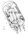
- the dyeing and centrifuging machine 4 includes a cylindrical container 46 with a horizontal axis supported on a base structure 48 by means of a series of air-cushions 50.
- the suspension system of the container 46 is described in detail in the present Applicant's Italian patent application No. 19131-A/89.
- the front end of the container 46 has a semi- circular opening.
- a closing cover 52 is disposed in correspondence with the open end.
- inside the cylindrical container 46 is a drum 54 with a shaft 56 which is supported by the container 46 by means of a pair of bearings 58 each protected by a mechanical seal for rotary shafts.
- the shaft 56 of the drum 54 is connected to a drive unit 60 (visible in Figure 1) by transmission belts 62.
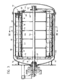
- the drum 54 includes an outer, perforated, cylindrical wall 64 and an inner, non-perforated, cylindrical wall 66 between which an annular chamber 67 is defined.
- the inner, cylindrical wall 66 is closed at the front by an end wall 68 and at the rear by a pair of spaced-apart walls 70, 72.
- the walls 68, 70 and 72 seal the space surrounded by the inner cylindrical wall 66 and are fixed to the shaft 56.
- the space described forms a liquid-tight chamber which contains the bath, that is, a quantity of liquid used in the process, the quantity being proportional to the number of kilograms of material to be dyed.
- a collecting chamber 74 defined between the walls 70 and 72 is connected to the annular chamber 67 by a plurality of holes 76.
- the collecting chamber 74 is connected to a reversible pump 80 (visible in Figure 1) by means of a pipe 78.
- the pipe 78 extends through the rear wall of the container 46 and its end carries a telescopic member 82 which can be made to slide by a pair of pneumatic cylinders 84.
- the telescopic member 82 is intended to establish a connection between the pipe 78 and a hole 86 in the wall 72 (see Figure 5).
- the reversible pump 80 is also connected to a second pipe 88 ( Figure 2) which communicates with the space between the drum 54 and the container 46.
- a plurality of channel-shaped elements 90 of perforated sheet metal is fixed to the cylindrical outer wall 64 of the drum 54 and defines a series of seats which, as will be explained further below, are intended to house respective tubes 14 with their reels 16.
- the annular chamber 67 between the cylindrical walls 64 and 66 is divided into two semi-annular chambers by two diametrally-opposed radial partitions 92 fixed to the inner wall 66 and to the outer wall 64.
- the two semi-annular chambers are open in correspondence with the open end of the container 46 and are intended to house respective material-holders 22.
- the radial partitions 92 constitute the guides on which the wheels 30 of the material-holder 22 are intended to roll when it is inserted in the chamber 67.
- the drum In order to load the material-holders 22 into the drum 54, the drum is stopped in a position in which the radial partitions 92 extend horizontally. This position is detected by a conventional position sensor (not shown). The end of the trolley 34 with the material-holders 22 and the reels 16 is brought up to the open end of the container 46. A pair of guides 94 is also provided in front of the dyeing machine 4 for aligning the trolley 34 with the container 46. The radial partitions 92 are aligned with the guides 32 on the trolley 34. The material-holder 22 is then inserted in the upper half of the annular chamber 27 simply by moving the material-holder 22 into the drum 54 axially.
- the drum 54 is rotated through 180° moving the material-holder 22 which has just been loaded into the lower half of the annular chamber 67 and bringing the empty half of the annular chamber 67 to the top.
- a second trolley 34 is then brought up to the machine 4 and a second material-holder 22 is inserted in the second semi-annular chamber.
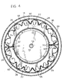
- FIGs 3 and 4 show the drum 54 loaded with the two material-holders 22.
- the wall 68 of the drum 54 carries two threaded rods 96 which are inserted in respective holes in the material-holder 22.
- a handwheel 98 is screwed onto each rod 96 to fix the material-holders 22 axially to the drum 54.
- the ends of the tubes 14 which face the rear end of the container 46 are arranged in correspondence with respective holes 76 in the end wall 70.
- the dye bath which is sent into the collecting chamber 74 through the pipe 78 thus flows into the cavities in the tubes 14 and passes through the reels 16 outwardly from the inside.
- the bath collects in the space between the drum 54 and the container 46 and returns through the pipe 88 to the pump 80 for recirculation.
- the dye bath can also flow in the opposite direction, that is, the bath is sent into the container 46 through the pipe 88 and passes through the reels 66 inwardly from the outside and then through the tubes 14, the collecting chamber 74, and the pipe 78 back to the pump 80.
- a coiled tube 100 through which a cooling or heating fluid flows, is disposed in the bottom of the cylindrical containers 46 so that the temperature of the dye bath can be varied according to a predetermined programme.
- the bath Upon completion of the dyeing, the bath is removed from the container 46 through a lower outlet valve, not shown in the drawings.
- the telescopic member 82 is then retracted so that the drum 54 is free to rotate.
- the drive unit 60 is then operated and rotates the drum 54 at a high speed.
- the spacer discs 18, which have larger diameters than the reels 16 are brought into contact with the inner surfaces of the respective channel-shaped elements 90.
- the bath which is removed from the reels 16 collects in the bottom of the container 46 and is then discharged from the equipment gradually through the outlet valves, not shown.
- the dyeing and centrifuging machine 4 can also dry the material upon completion of the centrifuging stage.
- the machine 4 is connected to a circuit for the forced supply of hot air as shown in Figure 6.
- a valve in the pipe 78 is indicated 101.
- Two hot-air supply pipes, indicated 102 and 104, are connected to the pipes 78 and 88 and to a fan unit, not shown.
- Respective valves 106 and 108 in the pipes 102 and 104 are closed during the dyeing stage.
- the valve 101 is closed, the valves 106 and 108 are opened and the hot-air supply unit is activated in order to dry the material.
- the dyeing and centrifuging machine 4 may be associated with an independent drying device 6 as shown in Figure 1.
- the material-holders 22 are removed from the drum 54 by reversing the process described above and are loaded on respective trolleys 34.
- the material-holders 22 are transported by the trolleys 34 to the drying device 6 which, in the embodiment illustrated in Figure 1, includes two superposed drying chambers 110 and 112.
- the platform 114 of a hoist which is sunk into the floor in front of the drying device 6 can be lowered below the floor level in order to bring the guides 32 of the trolley 34 to the same level as the base wall of the lower drying chamber 112.
- the base wall of the upper drying chamber 110 is aligned with the guides 32 of the trolley 34 when it is at floor level.
- a plant with a high production capacity may conveniently have a series of machines solely for dyeing, associated with a single machine solely for centrifuging the material.
- Figure 8 shows the rear end of a machine solely for dyeing.
- the casing 46 is supported on the floor by supports 118 instead of being suspended on air cushions 50.
- the motor, indicated 120, which rotates the drum 54 is of a size such that it can rotate the drum 54 at a speed suitable for effecting the rotation through 180° necessary for the loading and unloading of the material-holders 22.
- the shaft 56 of the drum 54 is supported on the casing 46 by bearings protected by mechanical rotary-shaft seals.
- Figure 7 shows a machine solely for centrifuging the material. This machine differs from the dyeing and centrifuging machine described above in that it has no pump for circulating the bath and in that the closure door 52 does not have to be of a size such as to withstand the pressure of the dye bath.
- the equipment according to the present invention may be used for bleaching treatments as well as dyeing treatments.
- the yarn may be made up into any kind of textile provided that it has the necessary degree of compactness. Instead of being wound on reels, the yarn may be wound on bobbins, cheeses, or beams, or may be in the form of tops or tufts.
Landscapes
- Engineering & Computer Science (AREA)
- Chemical & Material Sciences (AREA)
- Materials Engineering (AREA)
- Textile Engineering (AREA)
- Treatment Of Fiber Materials (AREA)
- Yarns And Mechanical Finishing Of Yarns Or Ropes (AREA)
Applications Claiming Priority (2)
| Application Number | Priority Date | Filing Date | Title |
|---|---|---|---|
| IT6762990 | 1990-08-08 | ||
| IT67629A IT1240538B (it) | 1990-08-08 | 1990-08-08 | Apparecchiatura per la tintura di filati confezionati in rocche e simili |
Publications (1)
| Publication Number | Publication Date |
|---|---|
| EP0470562A1 true EP0470562A1 (de) | 1992-02-12 |
Family
ID=11304038
Family Applications (1)
| Application Number | Title | Priority Date | Filing Date |
|---|---|---|---|
| EP91113156A Withdrawn EP0470562A1 (de) | 1990-08-08 | 1991-08-05 | Vorrichtung zum Färben von Garnspulen |
Country Status (2)
| Country | Link |
|---|---|
| EP (1) | EP0470562A1 (de) |
| IT (1) | IT1240538B (de) |
Cited By (5)
| Publication number | Priority date | Publication date | Assignee | Title |
|---|---|---|---|---|
| WO1996017990A1 (fr) * | 1994-12-07 | 1996-06-13 | Leonard System | Procede de teinture en bain court et machines le mettant en ×uvre |
| WO1999016953A1 (en) * | 1997-09-26 | 1999-04-08 | Loris Bellini S.P.A. | Plant for processing yarn on reels |
| CN100368622C (zh) * | 2001-05-25 | 2008-02-13 | 马斯特及龙基弗朗切斯科有限合伙两合公司 | 用于卷绕在卷轴或者类似卷装上的纱线的染色或者漂白设备 |
| WO2016055038A1 (de) * | 2014-10-06 | 2016-04-14 | Thies Gmbh & Co. Kg | Vorrichtung zur behandlung von textilen substraten mit einer flotte |
| IT202100001088A1 (it) * | 2021-01-22 | 2022-07-22 | Master Srl | Macchina per la tintura ecosostenibile, con indaco e altri coloranti a riduzione, di filati avvolti in rocche e altre confezioni similari |
Citations (3)
| Publication number | Priority date | Publication date | Assignee | Title |
|---|---|---|---|---|
| DE1964593A1 (de) * | 1969-12-23 | 1971-07-01 | Brueckner Appbau Michelstadt G | Verfahren und Vorrichtung zum Faerben von Warenwickeln |
| US3638458A (en) * | 1968-11-22 | 1972-02-01 | Teinturerie Des Francs | A tank for treating fibers |
| FR2268104A1 (de) * | 1974-04-16 | 1975-11-14 | Meccaniche L Pozzi Costruzioni |
-
1990
- 1990-08-08 IT IT67629A patent/IT1240538B/it active IP Right Grant
-
1991
- 1991-08-05 EP EP91113156A patent/EP0470562A1/de not_active Withdrawn
Patent Citations (3)
| Publication number | Priority date | Publication date | Assignee | Title |
|---|---|---|---|---|
| US3638458A (en) * | 1968-11-22 | 1972-02-01 | Teinturerie Des Francs | A tank for treating fibers |
| DE1964593A1 (de) * | 1969-12-23 | 1971-07-01 | Brueckner Appbau Michelstadt G | Verfahren und Vorrichtung zum Faerben von Warenwickeln |
| FR2268104A1 (de) * | 1974-04-16 | 1975-11-14 | Meccaniche L Pozzi Costruzioni |
Cited By (7)
| Publication number | Priority date | Publication date | Assignee | Title |
|---|---|---|---|---|
| WO1996017990A1 (fr) * | 1994-12-07 | 1996-06-13 | Leonard System | Procede de teinture en bain court et machines le mettant en ×uvre |
| WO1999016953A1 (en) * | 1997-09-26 | 1999-04-08 | Loris Bellini S.P.A. | Plant for processing yarn on reels |
| US6405568B1 (en) * | 1997-09-26 | 2002-06-18 | Loris Bellini S.P.A. | Plant for processing yarn on reels |
| CN100368622C (zh) * | 2001-05-25 | 2008-02-13 | 马斯特及龙基弗朗切斯科有限合伙两合公司 | 用于卷绕在卷轴或者类似卷装上的纱线的染色或者漂白设备 |
| WO2016055038A1 (de) * | 2014-10-06 | 2016-04-14 | Thies Gmbh & Co. Kg | Vorrichtung zur behandlung von textilen substraten mit einer flotte |
| IT202100001088A1 (it) * | 2021-01-22 | 2022-07-22 | Master Srl | Macchina per la tintura ecosostenibile, con indaco e altri coloranti a riduzione, di filati avvolti in rocche e altre confezioni similari |
| WO2022157602A1 (en) * | 2021-01-22 | 2022-07-28 | Master S.R.L. | Machine for ecologically sustainable dyeing, with indigo and other reduction dyes, of yarns wound on reels and other similar products |
Also Published As
| Publication number | Publication date |
|---|---|
| IT1240538B (it) | 1993-12-17 |
| IT9067629A1 (it) | 1992-02-08 |
| IT9067629A0 (it) | 1990-08-08 |
Similar Documents
| Publication | Publication Date | Title |
|---|---|---|
| US4916768A (en) | Washing and extracting method | |
| US4545135A (en) | Installations for spin-drying fibrous or porous materials | |
| US4426794A (en) | Apparatus for handling laundry | |
| US793510A (en) | Machine for dyeing, &c. | |
| US2285547A (en) | Extractor loading and unloading equipment | |
| US4856301A (en) | Washing and extracting machine | |
| ITMI20011115A1 (it) | Apparecchio di tintura o candeggio di filati avvolti su rocche o confezioni similari | |
| US6405568B1 (en) | Plant for processing yarn on reels | |
| CN100368622C (zh) | 用于卷绕在卷轴或者类似卷装上的纱线的染色或者漂白设备 | |
| IT9067629A1 (it) | Apparecchiatura per la tintura di filati confezionati in rocche e simili | |
| EP1344860B1 (de) | Behälter zum Färben von Textilmaterialen | |
| US3330139A (en) | Apparatus for the treatment of textiles or fabrics or the washing of laundry | |
| WO2001086052A1 (en) | Garment dyeing machine and plant | |
| EP1325975A2 (de) | Verfahren und Vorrichtung züm Dämpfen auf Formen von Strumpfwaren und dergeichen | |
| US20050257572A1 (en) | Device and method for the piece-wise or batch-wise refining of pieces of a substrate, in particular a textile substrate, under high pressure | |
| US3896642A (en) | Commercial laundry machine | |
| US1259839A (en) | Dyeing-machine. | |
| US11021831B2 (en) | Washing machine and operating method thereof | |
| CA1153571A (en) | Apparatus for treatment of materials | |
| CN118649854B (zh) | 一种铰链泡油烘干自动线 | |
| CN224186433U (zh) | 一种混纺纱线用浴染色装置 | |
| US3465549A (en) | Laundry machine | |
| EP0355651B1 (de) | Färbeeinrichtung | |
| EP1837431A1 (de) | Textilbehandlungsmaschine | |
| JPH02133656A (ja) | 染色機の繊維品取り出し装置 |
Legal Events
| Date | Code | Title | Description |
|---|---|---|---|
| PUAI | Public reference made under article 153(3) epc to a published international application that has entered the european phase |
Free format text: ORIGINAL CODE: 0009012 |
|
| AK | Designated contracting states |
Kind code of ref document: A1 Designated state(s): DE ES FR GB |
|
| 17P | Request for examination filed |
Effective date: 19920616 |
|
| 17Q | First examination report despatched |
Effective date: 19941118 |
|
| RAP1 | Party data changed (applicant data changed or rights of an application transferred) |
Owner name: FLAINOX S.R.L. |
|
| STAA | Information on the status of an ep patent application or granted ep patent |
Free format text: STATUS: THE APPLICATION IS DEEMED TO BE WITHDRAWN |
|
| 18D | Application deemed to be withdrawn |
Effective date: 19950530 |