EP0470679A2 - Presse pour la production des tablettes enrobées - Google Patents
Presse pour la production des tablettes enrobées Download PDFInfo
- Publication number
- EP0470679A2 EP0470679A2 EP91250217A EP91250217A EP0470679A2 EP 0470679 A2 EP0470679 A2 EP 0470679A2 EP 91250217 A EP91250217 A EP 91250217A EP 91250217 A EP91250217 A EP 91250217A EP 0470679 A2 EP0470679 A2 EP 0470679A2
- Authority
- EP
- European Patent Office
- Prior art keywords
- press
- radial arms
- receiving
- core
- rotor
- Prior art date
- Legal status (The legal status is an assumption and is not a legal conclusion. Google has not performed a legal analysis and makes no representation as to the accuracy of the status listed.)
- Granted
Links
Images

Classifications
-
- B—PERFORMING OPERATIONS; TRANSPORTING
- B30—PRESSES
- B30B—PRESSES IN GENERAL
- B30B11/00—Presses specially adapted for forming shaped articles from material in particulate or plastic state, e.g. briquetting presses, tabletting presses
- B30B11/34—Presses specially adapted for forming shaped articles from material in particulate or plastic state, e.g. briquetting presses, tabletting presses for coating articles, e.g. tablets
Definitions
- the invention relates to a press for producing coated core tablets according to the preamble of claim 1.
- a press of the generic type is previously known from EP 0.349.777 A1.
- the radial arms are mounted on a transfer device next to the press and can be radially retracted and extended.
- the transfer device is assigned an annular disk rotating with the radial arms, which is arranged below the radial arms and is provided with receiving nests for one core each, which are assigned to the transfer heads.
- the transfer device is driven in rotation about an axis parallel to the die table axis.
- the partial circles of the transfer heads and the partial circles of the matrices overlap by the distance between two matrices, the transfer heads being guided in the overlap area of the partial circles on the partial circle of the die table.
- the rotor of the press carries a guide ring with semicircular receiving troughs, in which the transfer heads of the transfer device are guided in order to cause the partial circles of the die table and the transfer heads to overlap. It has been shown that, especially at high rotational speeds of the rotor, there are problems when the transfer heads engage in the receiving troughs of the guide ring of the press. Problems can also arise when loosening the transfer heads from the receiving troughs of the guide ring. Interfering noises and undesired friction also occur due to the engagement of the transfer heads in the receiving troughs of the guide ring. Finally, the transfer device requires approximately the same overall volume as the press itself, since the partial circles of the transfer heads and the dies must be of the same size in order to achieve the same peripheral speeds.
- the invention is therefore based on the object to improve a press of the generic type in such a way that with the smallest possible construction volume of the press a synchronization of the transfer heads and the dies is ensured during the transfer of the cores in a simple manner and without friction and the resulting noise.
- the invention provides that the radial arms are mounted in the rotor and the receiving nests are arranged on the die table. According to the invention, the radial arms are thus mounted in the rotor itself, as a result of which a separate transfer device is no longer required.
- the overall volume of the press is thus limited to the volume required for the rotor.
- the receiving nests for the cores are arranged on the die table itself, only a simple movement of the radial arms over the die table is necessary in order to transfer the cores from the receiving nests into the dies.
- the receiving nests are arranged on a pitch circle of the die table which is larger than the pitch circle of the dies themselves, so that the radial arms in the rotor are mounted so that they can be extended and retracted, so as to move from the pitch circle of the dies into the pitch circle of the receiving nests and to be moved back.
- the transfer heads are moved back to a pitch circle that is smaller than the pitch circle of the matrices.
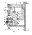
- the press for producing coated core tablets consists of a rotor 1, which is fixed to a rotating drive shaft 2 and is formed from an upper part 3, a lower part 4 and a die table 5 fastened in between, and from a fixed cam bell 6 with cam plate 7, vacuum plate 8 and upper ram curve 9.
- the drive shaft 2 is supported by means of bearings (not shown in more detail).
- the rotor 1 comprises a circular support plate 10 placed on the drive shaft 2, on which the annular lower part 4 for guiding the lower punches 11 is firmly attached.
- the heads 12 of the lower punches 11 are guided in curves, not shown in more detail, in order to bring about a vertical up and down movement of the punches 11.
- the circular disk-shaped die table 5 is placed on the lower part 4. On the one hand, this includes a pitch circle 13 for the dies 14, a pitch circle 15 with a larger diameter for the receiving nests 16 of the cores 17 and a radial clearance 18 with a diameter smaller than the pitch circle 13 for the dies 14 for a purpose described in more detail later.
- the upper part 3 fastened to the rotor 1 which serves to guide the upper punches 19 which are mounted in guide bushings 20 within the upper part 3.
- the heads 21 of the upper stamp 19 are guided in the upper stamp curve 9, which is fastened to the curve bell 6 fixed to the frame.
- the support plate 10 welded to the drive shaft 2 is firmly connected to a welded support cylinder 22 which is arranged concentrically to the axis of the drive shaft 2 and which forms an internal support for the upper part 3 and the lower part 4 of the rotor 1.
- the cam plate 7 is fixed on the cam bell 6 by means of threaded screws 23.
- the base body 24, which forms the cam plate 7 at its lower end, is arranged concentrically with the drive shaft 2.
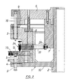
- the shape of the cam disc 7 results from the cross-section according to FIG are mounted radially to the axis of the drive shaft 2.
- the support cylinder 22 of the rotor 1 has radial through openings 28.
- support rollers 29 are mounted in the receiving slots via roller bearings 30, in particular nail bearings, which can be rotated on a bearing pin 31 arranged transversely to the longitudinal axis of the pistons 26.
- a limiting disk 32 for a compression spring 33 is mounted, which is supported on the radially inward end face of the polygon bushes 27 and causes a constant contact force for the support roller 29 on the outer curve of the cam disk 7.
- the press shown in the figures carries on the table 5 twenty-four dies 14 with associated lower and upper punches 11, 19 and with associated radial arms 25 in the form of the pistons 26.
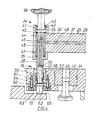
- Each piston 26 carries at its radially outer, free end a transfer head 34 which 4 together with a receiving nest 16 underneath and the associated die 14 can be seen in an enlarged view.
- Each transfer head 34 comprises a head piece 35 which is provided with a bore 36 for receiving the piston 26.
- the head piece 35 is fixed on the piston 26 in a rotationally fixed and immovable manner.
- a core punch 38 extends transversely to the longitudinal axis 37 of the piston 26 and parallel to the axis 2 ′ of the drive shaft 2, which serves to receive and transfer cores 17.
- the core punch 38 penetrates a lower bore 39 of the head piece 35 with a sliding guide and is further guided by a collar 41 sliding in an inner bore 40 in the upper region of the head piece 35.
- an annular disk 42 is fastened at the upper end by means of a snap ring 43.
- a compression spring 44 extends, which causes a permanent stop of the collar 41 of the core punch 38 on the annular disc 42.
- a longitudinal bore 45 is made within the core punch 38, which ends approximately in the middle as a blind bore and opens via a transverse bore 46 into the interior space 47 formed by the inner bore 40 of the head piece 35.
- a longitudinal bore 48 of the piston 26 opens into this, which ends approximately in the longitudinal central region of the piston 26 and opens via a transverse bore 49 with an axial channel 50 of the polygonal bushing 27.
- the axial channel 50 is in turn connected via a bore 51 running parallel to the axis 2 ′ of the drive shaft 2 within the upper part 3 and opening into the vacuum chamber 52 of the fixed vacuum disk 8.
- This is connected via a pipe section 53 to a bore 54 in the cam bell 6, to which a controllable vacuum device, not shown, is connected. From this vacuum device, a negative pressure can be generated in the above-described way at the suction mouth 55 of the core punch 38 for receiving the core 17, for which purpose the suction mouth 55 is designed as a receiving recess adapted to the shape of the core 17.
- Each receiving nest 16 consists of an outer guide bush 56 which is firmly inserted into an axial bore of the die 5, a hollow outer punch 57 which is guided in the guide bush 56 and an inner punch 58 which in turn is guided in the outer punch 57.
- An outer compression spring 59 is arranged between the outer guide bush 56 and the outer punch 57.
- An inner compression spring 61 is arranged between the outer die 57 and a collar 60 of the inner die 58, which act on the outer die 57 or the inner die 58.
- the lower head 62 of the inner die 58 is guided in a guide plate 63, which is screwed together with the guide bush 56 via threaded screws 64 in the die table 5.
- the head 62 of the inner punch 58 is acted upon by a cam 65 which is mounted fixed to the frame.
- a radial inward movement of the transfer head 34 from the pitch circle 15 of the receiving nests 16 into the pitch circle 13 of the dies 14 is carried out under the vacuum of the axial channel 50 via the cam plate 7 and the associated radially acting compression spring 33.
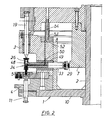
- the transfer head is now for core transfer according to FIG. 2 above a die 14.
- the lower punch 11 is lowered, it is partially filled with sub powder material by a filling and metering device (not shown).
- the core 17 is now pressed into the sub-powder material located on the lower punch 11 within the die 14 by means of the transfer head 34.
- the core punch 38 is pressed in under the action of the upper punch 19 against the action of the compression spring 47 while maintaining the vacuum.
- the rotor 1 of the press for the production of coated core tablets rotates at a high rotational speed, so that e.g. 24 stamping tools an output of 200,000 tablets per hour can be achieved.
- the core 17 must be pressed centrically into the sub-powder layer in order to avoid a displacement of the core 17 under the action of centrifugal forces.
- each core punch 38 is provided with a head 66 which does not lead to the safe removal of the core punch 38 shows the guide curve shown in more detail, which ensures the vertical lifting of the core punch 38 in addition to the compression spring 47.
Landscapes
- Engineering & Computer Science (AREA)
- Mechanical Engineering (AREA)
- Medicinal Preparation (AREA)
- Press Drives And Press Lines (AREA)
- Powder Metallurgy (AREA)
- Glanulating (AREA)
Applications Claiming Priority (2)
| Application Number | Priority Date | Filing Date | Title |
|---|---|---|---|
| DE4025484A DE4025484C1 (fr) | 1990-08-08 | 1990-08-08 | |
| DE4025484 | 1990-08-08 |
Publications (3)
| Publication Number | Publication Date |
|---|---|
| EP0470679A2 true EP0470679A2 (fr) | 1992-02-12 |
| EP0470679A3 EP0470679A3 (en) | 1992-11-19 |
| EP0470679B1 EP0470679B1 (fr) | 1995-04-12 |
Family
ID=6412063
Family Applications (1)
| Application Number | Title | Priority Date | Filing Date |
|---|---|---|---|
| EP91250217A Expired - Lifetime EP0470679B1 (fr) | 1990-08-08 | 1991-08-05 | Presse pour la production des tablettes enrobées |
Country Status (6)
| Country | Link |
|---|---|
| US (1) | US5256046A (fr) |
| EP (1) | EP0470679B1 (fr) |
| JP (1) | JP2552211B2 (fr) |
| AT (1) | ATE121014T1 (fr) |
| DE (2) | DE4025484C1 (fr) |
| ES (1) | ES2071909T3 (fr) |
Cited By (1)
| Publication number | Priority date | Publication date | Assignee | Title |
|---|---|---|---|---|
| WO2016009248A2 (fr) | 2013-12-11 | 2016-01-21 | Shah, Abhay | Procédé de fabrication d'une pièce moulée |
Families Citing this family (9)
| Publication number | Priority date | Publication date | Assignee | Title |
|---|---|---|---|---|
| DE10026731C2 (de) * | 2000-05-17 | 2002-08-14 | Fette Wilhelm Gmbh | Rundläufer-Tablettenpresse für die Herstellung von mehrschichtigen Tabletten |
| KR100897837B1 (ko) * | 2001-12-24 | 2009-05-15 | 테바 파마슈티컬 인더스트리즈 리미티드 | 분말 또는 과립 물질의 압착된 환상체 내에 싸인 활성성분의 코어 정제를 갖는 제형과, 이의 제조 방법 및 툴링 |
| US20040052843A1 (en) * | 2001-12-24 | 2004-03-18 | Lerner E. Itzhak | Controlled release dosage forms |
| US7178562B2 (en) * | 2004-04-08 | 2007-02-20 | Graham Packaging Pet Technologies Inc. | Pellet transfer apparatus and method |
| DE102005030312B4 (de) * | 2005-06-23 | 2011-05-05 | Korsch Ag | Rundläufer-Tablettiermaschine und Verfahren zur Herstellung einer Mehrschichttablette |
| EP2110232B1 (fr) * | 2008-04-18 | 2016-09-14 | Korsch AG | Dispositif d'insertion d'inserts dans des matrices d'une presse rotative pour comprimés |
| DE102011051653A1 (de) | 2011-07-07 | 2013-01-10 | Lts Lohmann Therapie-Systeme Ag | Quellfähige Manteltablette |
| US20200171770A1 (en) * | 2018-12-04 | 2020-06-04 | Right Value Drug Stores, Llc | Automated pallet press |
| WO2023222688A1 (fr) | 2022-05-18 | 2023-11-23 | Korsch Ag | Dispositif pour insérer au moins un objet dans au moins une matrice d'une machine à fabriquer des comprimés |
Family Cites Families (10)
| Publication number | Priority date | Publication date | Assignee | Title |
|---|---|---|---|---|
| US2514486A (en) * | 1945-11-21 | 1950-07-11 | Lee B Green | Molding machine |
| DE1023191B (de) * | 1954-04-15 | 1958-01-23 | John Holroyd & Co Ltd | Verfahren und Vorrichtung zum Herstellen ueberzogener Tabletten |
| DE1095462B (de) * | 1957-02-19 | 1960-12-22 | John Holroyd & Company Ltd | Vorrichtung zum Herstellen ueberzogener Tabletten aus auf einer Tablettenpresse hergestellten Kerntabletten |
| US2946298A (en) * | 1957-11-13 | 1960-07-26 | Arthur Colton Company | Compression coating tablet press |
| US2963993A (en) * | 1959-01-20 | 1960-12-13 | John Holroyd & Company Ltd | Machines for making coated tablets by compression |
| US3677673A (en) * | 1970-08-25 | 1972-07-18 | Pennwalt Corp | Rotary press |
| US4292017A (en) * | 1980-07-09 | 1981-09-29 | Doepel Wallace A | Apparatus for compressing tablets |
| US4362493A (en) * | 1980-07-09 | 1982-12-07 | Doepel Wallace A | Apparatus for compressing tablets |
| US5088915A (en) * | 1988-06-08 | 1992-02-18 | Korsch Ohg Maschinenfabrik | Coated-core press |
| DE9003241U1 (de) * | 1990-03-17 | 1990-06-13 | Korsch Maschinenfabrik, 1000 Berlin | Rundlaufpresse |
-
1990
- 1990-08-08 DE DE4025484A patent/DE4025484C1/de not_active Expired - Fee Related
-
1991
- 1991-08-05 AT AT91250217T patent/ATE121014T1/de not_active IP Right Cessation
- 1991-08-05 ES ES91250217T patent/ES2071909T3/es not_active Expired - Lifetime
- 1991-08-05 DE DE59105154T patent/DE59105154D1/de not_active Expired - Fee Related
- 1991-08-05 EP EP91250217A patent/EP0470679B1/fr not_active Expired - Lifetime
- 1991-08-07 US US07/741,142 patent/US5256046A/en not_active Expired - Fee Related
- 1991-08-08 JP JP3223321A patent/JP2552211B2/ja not_active Expired - Lifetime
Cited By (3)
| Publication number | Priority date | Publication date | Assignee | Title |
|---|---|---|---|---|
| WO2016009248A2 (fr) | 2013-12-11 | 2016-01-21 | Shah, Abhay | Procédé de fabrication d'une pièce moulée |
| EP3079894A4 (fr) * | 2013-12-11 | 2017-10-11 | Roland Saur-Brosch | Procédé de fabrication d'une pièce moulée |
| US10064827B2 (en) | 2013-12-11 | 2018-09-04 | Roland SAUR-BROSCH | Method for the production of a molding |
Also Published As
| Publication number | Publication date |
|---|---|
| US5256046A (en) | 1993-10-26 |
| ES2071909T3 (es) | 1995-07-01 |
| EP0470679B1 (fr) | 1995-04-12 |
| DE59105154D1 (de) | 1995-05-18 |
| EP0470679A3 (en) | 1992-11-19 |
| ATE121014T1 (de) | 1995-04-15 |
| JPH08132294A (ja) | 1996-05-28 |
| JP2552211B2 (ja) | 1996-11-06 |
| DE4025484C1 (fr) | 1991-10-10 |
Similar Documents
| Publication | Publication Date | Title |
|---|---|---|
| EP0349777B1 (fr) | Presse pour enrober des noyaux | |
| EP3079894B1 (fr) | Procédé de fabrication d'une pièce moulée | |
| EP1005425B1 (fr) | Dispositif pour le dosage et la distribution de poudre dans des capsules de gelatine dure ou analogues | |
| EP0470679B1 (fr) | Presse pour la production des tablettes enrobées | |
| DE2317511A1 (de) | Stanzpresse | |
| DE3227479C2 (de) | Spanlos geformter Offenend-Spinnrotor sowie Verfahren zur Herstellung eines solchen Offenend-Spinnrotors | |
| DE102013002267B4 (de) | Tablettenpresse | |
| DE7736038U1 (de) | Vorrichtung zum ausstanzen und tiefziehen von werkstuecken aus blech o.dgl. | |
| WO2017157603A1 (fr) | Procédé et dispositif d'éjection de couvercles et d'étiquettes | |
| EP2036710B1 (fr) | Rotor pour presse rotative pour comprimés | |
| DE10026731C2 (de) | Rundläufer-Tablettenpresse für die Herstellung von mehrschichtigen Tabletten | |
| EP1165308B1 (fr) | Presse a table tournante pourvue des etampes remplac ables | |
| DE2155615B2 (de) | Werkzeugkopf für FaIt- und/oder Gewindeformmaschinen | |
| DE19963263C2 (de) | Rundlaufpresse mit auswechselbaren Einsatzstempeln | |
| DE2064762C3 (de) | Vorrichtung zum Randbeschneiden von Tiefziehteilen | |
| DE2503664B2 (de) | Flaschenkapsel-Anrollkopf | |
| CH638720A5 (de) | Presse. | |
| DE6947337U (de) | Verfahren und vorrichtung zur verformung von materialien. | |
| DE2950674A1 (de) | Fertigungs- bzw. montageeinrichtung | |
| DE1023191B (de) | Verfahren und Vorrichtung zum Herstellen ueberzogener Tabletten | |
| DE1291629C2 (de) | Tablettenpresse mit umlaufendem matrizentisch | |
| DE69022438T2 (de) | Kreisschere. | |
| DE2062977A1 (de) | Vorrichtung zum Herstellen von oben offenen Hohlkörpern | |
| DE2550672A1 (de) | Presse zur herstellung von tabletten in matrizen | |
| DE202023101264U1 (de) | Rundläufer-Tablettenpresse und Druckschiene als Kurvenabschnitt einer Steuerkurve für die Stempel eines Rotors der Rundläufer-Tablettenpresse |
Legal Events
| Date | Code | Title | Description |
|---|---|---|---|
| PUAI | Public reference made under article 153(3) epc to a published international application that has entered the european phase |
Free format text: ORIGINAL CODE: 0009012 |
|
| AK | Designated contracting states |
Kind code of ref document: A2 Designated state(s): AT BE CH DE DK ES FR GB GR IT LI LU NL SE |
|
| PUAL | Search report despatched |
Free format text: ORIGINAL CODE: 0009013 |
|
| AK | Designated contracting states |
Kind code of ref document: A3 Designated state(s): AT BE CH DE DK ES FR GB GR IT LI LU NL SE |
|
| 17P | Request for examination filed |
Effective date: 19930510 |
|
| 17Q | First examination report despatched |
Effective date: 19940520 |
|
| GRAA | (expected) grant |
Free format text: ORIGINAL CODE: 0009210 |
|
| AK | Designated contracting states |
Kind code of ref document: B1 Designated state(s): AT BE CH DE DK ES FR GB GR IT LI LU NL SE |
|
| PG25 | Lapsed in a contracting state [announced via postgrant information from national office to epo] |
Ref country code: GR Free format text: LAPSE BECAUSE OF FAILURE TO SUBMIT A TRANSLATION OF THE DESCRIPTION OR TO PAY THE FEE WITHIN THE PRESCRIBED TIME-LIMIT Effective date: 19950412 Ref country code: NL Free format text: LAPSE BECAUSE OF NON-PAYMENT OF DUE FEES Effective date: 19950412 Ref country code: DK Effective date: 19950412 |
|
| REF | Corresponds to: |
Ref document number: 121014 Country of ref document: AT Date of ref document: 19950415 Kind code of ref document: T |
|
| REF | Corresponds to: |
Ref document number: 59105154 Country of ref document: DE Date of ref document: 19950518 |
|
| ITF | It: translation for a ep patent filed | ||
| ET | Fr: translation filed | ||
| PG25 | Lapsed in a contracting state [announced via postgrant information from national office to epo] |
Ref country code: SE Effective date: 19950712 |
|
| PG25 | Lapsed in a contracting state [announced via postgrant information from national office to epo] |
Ref country code: AT Effective date: 19950805 |
|
| PG25 | Lapsed in a contracting state [announced via postgrant information from national office to epo] |
Ref country code: CH Effective date: 19950831 Ref country code: LI Effective date: 19950831 Ref country code: LU Free format text: LAPSE BECAUSE OF NON-PAYMENT OF DUE FEES Effective date: 19950831 |
|
| GBT | Gb: translation of ep patent filed (gb section 77(6)(a)/1977) |
Effective date: 19950814 |
|
| NLV1 | Nl: lapsed or annulled due to failure to fulfill the requirements of art. 29p and 29m of the patents act | ||
| REG | Reference to a national code |
Ref country code: FR Ref legal event code: TP |
|
| PLBE | No opposition filed within time limit |
Free format text: ORIGINAL CODE: 0009261 |
|
| REG | Reference to a national code |
Ref country code: ES Ref legal event code: PC2A Owner name: KORSCH PRESSEN GMBH |
|
| STAA | Information on the status of an ep patent application or granted ep patent |
Free format text: STATUS: NO OPPOSITION FILED WITHIN TIME LIMIT |
|
| 26N | No opposition filed | ||
| REG | Reference to a national code |
Ref country code: GB Ref legal event code: 732E |
|
| REG | Reference to a national code |
Ref country code: CH Ref legal event code: PL |
|
| REG | Reference to a national code |
Ref country code: GB Ref legal event code: IF02 |
|
| PGFP | Annual fee paid to national office [announced via postgrant information from national office to epo] |
Ref country code: DE Payment date: 20081029 Year of fee payment: 18 |
|
| PG25 | Lapsed in a contracting state [announced via postgrant information from national office to epo] |
Ref country code: DE Free format text: LAPSE BECAUSE OF NON-PAYMENT OF DUE FEES Effective date: 20100302 |
|
| PGFP | Annual fee paid to national office [announced via postgrant information from national office to epo] |
Ref country code: ES Payment date: 20100830 Year of fee payment: 20 |
|
| PGFP | Annual fee paid to national office [announced via postgrant information from national office to epo] |
Ref country code: IT Payment date: 20100825 Year of fee payment: 20 Ref country code: FR Payment date: 20100901 Year of fee payment: 20 |
|
| PGFP | Annual fee paid to national office [announced via postgrant information from national office to epo] |
Ref country code: GB Payment date: 20100823 Year of fee payment: 20 |
|
| PGFP | Annual fee paid to national office [announced via postgrant information from national office to epo] |
Ref country code: BE Payment date: 20100823 Year of fee payment: 20 |
|
| REG | Reference to a national code |
Ref country code: GB Ref legal event code: PE20 Expiry date: 20110804 |
|
| BE20 | Be: patent expired |
Owner name: *KORSCH PRESSE G.M.B.H. Effective date: 20110805 |
|
| PG25 | Lapsed in a contracting state [announced via postgrant information from national office to epo] |
Ref country code: GB Free format text: LAPSE BECAUSE OF EXPIRATION OF PROTECTION Effective date: 20110804 |
|
| REG | Reference to a national code |
Ref country code: ES Ref legal event code: FD2A Effective date: 20120110 |
|
| PG25 | Lapsed in a contracting state [announced via postgrant information from national office to epo] |
Ref country code: ES Free format text: LAPSE BECAUSE OF EXPIRATION OF PROTECTION Effective date: 20110806 |