EP0470700B1 - Méthode et appareillage de détection du coefficient de frottement du revêtement routier, et méthode et système de direction des quatre roues pour des véhicules, utilisant le coefficient de frottement du revêtement routier détecté - Google Patents
Méthode et appareillage de détection du coefficient de frottement du revêtement routier, et méthode et système de direction des quatre roues pour des véhicules, utilisant le coefficient de frottement du revêtement routier détecté Download PDFInfo
- Publication number
- EP0470700B1 EP0470700B1 EP91306077A EP91306077A EP0470700B1 EP 0470700 B1 EP0470700 B1 EP 0470700B1 EP 91306077 A EP91306077 A EP 91306077A EP 91306077 A EP91306077 A EP 91306077A EP 0470700 B1 EP0470700 B1 EP 0470700B1
- Authority
- EP
- European Patent Office
- Prior art keywords
- steering
- road surface
- angle
- friction coefficient
- steering wheel
- Prior art date
- Legal status (The legal status is an assumption and is not a legal conclusion. Google has not performed a legal analysis and makes no representation as to the accuracy of the status listed.)
- Expired - Lifetime
Links
Images


Classifications
-
- B—PERFORMING OPERATIONS; TRANSPORTING
- B62—LAND VEHICLES FOR TRAVELLING OTHERWISE THAN ON RAILS
- B62D—MOTOR VEHICLES; TRAILERS
- B62D6/00—Arrangements for automatically controlling steering depending on driving conditions sensed and responded to, e.g. control circuits
-
- B—PERFORMING OPERATIONS; TRANSPORTING
- B62—LAND VEHICLES FOR TRAVELLING OTHERWISE THAN ON RAILS
- B62D—MOTOR VEHICLES; TRAILERS
- B62D7/00—Steering linkage; Stub axles or their mountings
- B62D7/06—Steering linkage; Stub axles or their mountings for individually-pivoted wheels, e.g. on king-pins
- B62D7/14—Steering linkage; Stub axles or their mountings for individually-pivoted wheels, e.g. on king-pins the pivotal axes being situated in more than one plane transverse to the longitudinal centre line of the vehicle, e.g. all-wheel steering
- B62D7/15—Steering linkage; Stub axles or their mountings for individually-pivoted wheels, e.g. on king-pins the pivotal axes being situated in more than one plane transverse to the longitudinal centre line of the vehicle, e.g. all-wheel steering characterised by means varying the ratio between the steering angles of the steered wheels
- B62D7/159—Steering linkage; Stub axles or their mountings for individually-pivoted wheels, e.g. on king-pins the pivotal axes being situated in more than one plane transverse to the longitudinal centre line of the vehicle, e.g. all-wheel steering characterised by means varying the ratio between the steering angles of the steered wheels characterised by computing methods or stabilisation processes or systems, e.g. responding to yaw rate, lateral wind, load, road condition
-
- G—PHYSICS
- G01—MEASURING; TESTING
- G01N—INVESTIGATING OR ANALYSING MATERIALS BY DETERMINING THEIR CHEMICAL OR PHYSICAL PROPERTIES
- G01N19/00—Investigating materials by mechanical methods
- G01N19/02—Measuring coefficient of friction between materials
-
- B—PERFORMING OPERATIONS; TRANSPORTING
- B60—VEHICLES IN GENERAL
- B60T—VEHICLE BRAKE CONTROL SYSTEMS OR PARTS THEREOF; BRAKE CONTROL SYSTEMS OR PARTS THEREOF, IN GENERAL; ARRANGEMENT OF BRAKING ELEMENTS ON VEHICLES IN GENERAL; PORTABLE DEVICES FOR PREVENTING UNWANTED MOVEMENT OF VEHICLES; VEHICLE MODIFICATIONS TO FACILITATE COOLING OF BRAKES
- B60T2210/00—Detection or estimation of road or environment conditions; Detection or estimation of road shapes
- B60T2210/10—Detection or estimation of road conditions
- B60T2210/12—Friction
Definitions
- the preset invention relates to a method and an apparatus for determining the ease of slip on road surfaces on running vehicles, that is, for detecting the friction coefficient of road surface.
- the present invention relates to a method and a system for four-wheel steering of vehicles in which the steering of rear wheels is controlled by using the detected friction coefficient of road surface, when the front wheels of vehicle are steered.
- the method for detecting the friction coefficient of road surface and the method for four-wheel steering of vehicles have been disclosed, for example, in Unexamined Japanese Patent Publication No. 60-148769 (US 4,964,481, DE 3,500,797, GB 2,153,311, FR 2,558,130).
- the friction coefficient of road surface is detected on the basis of the operating angle of steering wheel of vehicle, the vehicle speed, and the lateral acceleration acting on the vehicle body.
- the steering angle of rear wheels on vehicle is corrected in accordance with the friction coefficient of road surface detected by the former method.
- the slip angle of front wheel is calculated from the operating angle of steering wheel and the vehicle speed.
- the slip angle correlates with the cornering force of front wheel, and the cornering force varies with the friction coefficient of road surface. Meanwhile, it is well known that the cornering force is proportional to the lateral acceleration acting on the vehicle body. If the operating angle, the vehicle speed, and the lateral acceleration are detected, therefore, the friction coefficient of road surface can be calculated on the basis of the detection results.
- the lateral acceleration which the vehicle body is to be subjected during the turning of vehicle actually acts on the body only when some time elapses after the start of turning. Since the lateral acceleration acts on the vehicle body with a delay after the start of turning of the vehicle, there is a delay in detecting the lateral acceleration of vehicle body. For this reason, the friction coefficient of road surface cannot be calculated quickly by the above-described method.
- the cornering force calculated from the lateral acceleration acting on the vehicle body is equivalent to the sum of the cornering forces generated on the front and rear wheels.
- the slip angle of not only the front wheels but also the rear wheels should be taken into consideration.
- the friction coefficient of road surface cannot be exactly detected, resulting in poor accuracy of the detected friction coefficient of road surface.
- the first object of the present invention is to provide a method and an apparatus for quickly and accurately detecting a friction coefficient of the road surface at the initial turning stage of vehicle.
- the second object of the present invention is to provide a method and a system for four-wheel steering of vehicle in which the steering control of rear wheels can be performed in an optimum manner when the front wheels are steered.
- the first object can be achieved by the method and apparatus for detecting a friction coefficient of the road surface according to the present invention, the method comprising:
- the friction coefficient of road surface is calculated by using relationships of three conditions; firstly, a slip angle of front wheels is determined in accordance with the operating angle of steering wheel, the vehicle speed, and the friction coefficient of road surface, secondly, a cornering force of front wheels is determined in accordance with the slip angle and the friction coefficient of road surface, and thirdly, the cornering force is proportional to the operating pressure of power steering unit.
- the friction coefficient of road surface can be exactly detected, its detecting accuracy being increased, by taking account of the operating pressure corresponding to the cornering force of front wheels only.
- the operating pressure of hydraulic power steering unit is generated quickly at the initial turning stage of vehicle, in other words, at the start of operation of steering wheel, so that the friction coefficient of road surface can be exactly detected even at the initial turning stage of vehicle.
- the friction coefficient of road surface is calculated only when the operating angle of steering wheel increases or is held at a predetermined angular position during the operation of steering wheel, so that a stable and reliable friction coefficient of surface road can be calculated.
- the detected signal indicating the operating pressure of power steering unit may be filtered to compensate the advance in phase of operating pressure in relation to the operation of steering wheel.
- the advance in phase of operating pressure is caused by the characteristics of a steering valve in the power steering unit and the inertia effect of front wheels.
- the filtering of the detected signal or the operating pressure further increases the detection accuracy of friction coefficient of road surface.
- the operating pressure of hydraulic power steering unit is preferably detected as the pressure difference between right and left pressure chambers in the power steering unit. If the operating pressure of power steering unit is detected in such a manner, a discrimination can be made whether or not the condition of the second step described above has been satisfied, that is, whether or not the proper steering situation has been detected, by taking account of a steering direction of the front wheels corresponding to the acting direction of operating pressure and a steering direction of the front wheels corresponding to the operating angle of steering wheel.
- the friction coefficient of road surface in the third step is calculated only when the proper steering situation is detected, the friction coefficient of road surface is not calculated, for example, when the vehicle is slaloming and the steering phases determined on the basis of the operating pressure and the operating angle of steering wheel are opposite. As a result, there is no error in friction coefficient of road surface, and the detection accuracy is further increased.
- the calculated friction coefficient of road surface should not be set as a new friction coefficient. This prevents a sudden change of the detected friction coefficient of road surface, thus providing a stable friction coefficient of road surface.
- the apparatus for detecting a friction coefficient of the road surface is an apparatus for carrying out the above-described method.
- the apparatus has advantages similar to those of the detecting method.
- the second object of the present invention described above is achieved by a four-wheel steering method of vehicle according to the present invention, the four-wheel steering method comprising: a first step of detecting each of an operating angle of the steering wheel, a vehicle speed and an operating pressure of a hydraulic power steering unit for the front wheels, a second step of detecting a proper steering situation in which a condition of increase in the steering angle of front wheels is satisfied during the operating of steering wheel, a third step of calculating a friction coefficient of the road surface on the basis of the data detected in the first step only when the proper steering situation is detected, and a fourth step of calculating an equiphase steering angle of rear wheels to steer the rear wheels to the same direction as the steering direction of front wheels, on the basis of the rotating angle of steering wheel and the friction coefficient of road surface obtained in the third step, the equiphase steering angle of rear wheels calculated in the fourth step being increased by a predetermined increment as the friction coefficient of road surface calculated in the third step decreases.
- the friction coefficient of road surface can be detected accurately at the initial turning stage of vehicle, as with the above-described detecting method, so that the optimum equiphase steering angle of rear wheels can be calculated on the basis of the friction coefficient of road surface thus detected.
- the turning ability of vehicle can be fully insured even when the friction coefficient of road surface is low, since the equiphase steering angle of rear wheels is increased with the decrease in friction coefficient of road surface.
- the increase in equiphase steering angle of rear wheels caused by a low friction coefficient of road surface should be preferably restricted with the increase in vehicle speed. This restriction permits the optimum correction of equiphase steering angle of rear wheels in accordance with the decrease in friction coefficient of road surface when the vehicle is running at either a medium or a high speed, resulting in higher steering stability of vehicle.
- the steering angle of rear wheels by taking account of an opposite phase steering angle for steering the rear wheels in the direction opposite to the steering of front wheels in addition to the equiphase steering angle described above.
- This opposite phase steering angle is calculated in accordance with the angular velocity of steering wheel.
- the four-wheel steering system of vehicle is a system for implementing the above-described steering method, and has advantages similar to those of the four-wheel steering method.
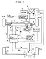
- Fig. 1 which schematically shows a four-wheel steering system of vehicle
- the left front wheel FW L and the right front wheel FW R of the vehicle are steered by means of a power steering unit 1.
- the power steering unit 1 is equipped with a front steering actuator 3 having a hydraulic cylinder, and both piston rods of the front steering actuator 3 are connected to the left front wheel FW L and the right front wheel FW R via a tie rod 2.
- the front steering actuator 3 incorporates a rack and pinion mechanism (not shown) which is connected to a steering wheel 4, and its rack is formed as one piston rod of the front steering actuator 3. Therefore, when the steering wheel 4 is operated, the front steering actuator 3 is driven via the rack and pinion mechanism.
- the front steering actuator 3 is in fluid communication with a front steering valve 5.
- the front steering valve 5 is mechanically connected to the steering wheel 4 . Therefore, the front steering valve 5 can be operated by the steering wheel 4.
- the front steering valve 5 is connected to one hydraulic pump 7 in a pump unit 6. That is, the pump unit 6 has a pair of hydraulic pumps 7, 9 which are tandem connected with each other. These hydraulic pumps are driven by a vehicle engine 8.
- the other hydraulic pump 9 is connected to a rear steering actuator 11 via a rear steering valve 10.
- This rear steering actuator 11 includes a hydraulic cylinder similar to that in the above-mentioned front steering actuator 3. Both piston rods of the rear steering actuator 11 are connected to the left rear wheel RW L and the right rear wheel RW R via a tie rod 12.
- the suction ports of hydraulic pumps 7, 9 are connected to a reservoir tank 14.
- the hydraulic fluid is fed from the hydraulic pump 7 to the front steering actuator 3 by the changeover of the front steering valve 5.
- the front steering actuator 3 operates in accordance with the rotational direction of steering wheel 4; thus, the front wheels FW are steered.
- the rear wheels RW can also be steered via the rear steering valve 10 and the rear steering actuator 11. Since the rear steering valve 10 is electrically connected to a controller 15 as shown in Fig. 1, the controller 15 supplies a control signal S R to the rear steering valve 10 in accordance with the running condition of vehicle to control the changeover of the rear steering valve 10. As a result, the pressure and feeding direction of hydraulic fluid, which is fed from the hydraulic pump 9 to the rear steering actuator 11 via the rear steering valve 10, is controlled, and then the rear wheels RW L and RW R are steered.
- the controller 15 is also electrically connected to the front steering valve 5, so that the front steering valve 5 can receive a control signal S F from the controller 15.
- the front steering valve 5 controls the feed pressure of hydraulic fluid to the front steering actuator 3 so as to advance the steering phase of front wheels FW in relation to the operation of steering wheel 4.
- the controller 15 For the controller 15 to produce control signals S F , S R which are to be fed to the steering valves 5, 10, the controller 15 is electrically connected to various sensors and meters. The meters supply detection signals indicating the operating conditions of various devices to the controller 15.
- the above-mentioned sensors include a vehicle speed sensor 26 for detecting the vehicle speed, a sensor 16 for detecting the operating angle ⁇ H of steering wheel 4, a sensor 17 for detecting the actual steering angle ⁇ Ra of rear wheels RW, and a sensor for detecting the operating pressure of front steering actuator 3. Sensor signals from these sensors are fed to the controller 15.
- the sensor for detecting the operating pressure of front steering actuator 3 includes a pair of pressure sensors 18, 19. These pressure sensors 18, 19 detect the pressures in a right and left pressure chambers (not shown) in the front steering actuator 3, respectively, to send their sensor signals to the controller 15.
- the controller 15 calculates the pressure difference between the two pressure chambers on the basis of the sensor signals from a pair of pressure sensors 18, 19, and this pressure difference is used as the operating pressure ⁇ P of front steering actuator 3.
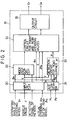
- controller 15 has an input circuit 30 which receives the sensor signals indicating the operating angle ⁇ H of steering wheel 4, the vehicle speed V, and the actual steering angle ⁇ Ra of rear wheels RW from the sensors 16, 26, 17, respectively, and an analog/digital (A/D) converter 31 which receives the sensor signals indicating the pressures P L , P R in the pressure chambers of front steering actuator 3 detected by the pressure sensors 18, 19, respectively.
- A/D analog/digital
- the input circuit 30 is connected to a decision circuit 32, which selects one steering control mode of the vehicle from a number of modes on the basis of the data supplied through the input circuit 30, namely, the data indicating the operating angle ⁇ H , the vehicle speed V, and the actual steering angle ⁇ Ra of rear wheels RW, and the detection data from the meters.
- These steering control modes include an interruption mode of the steering control, an-opposite phase steering mode of the rear wheels RW in which the rear wheels RW are steered in the opposite phase with the front wheels FW when the vehicle speed is low and the operating angle ⁇ H is large (for example, V ⁇ 30km/h and ⁇ H ⁇ 230° ), and a phase control mode in which the steering phases of front and rear wheels are controlled when the vehicle speed is in the medium and high speed range (for example, V ⁇ 40km/h).
- the input circuit 30 and the A/D converter 31 are connected to a detection circuit 33 for detecting the friction coefficient of road surface, namely the road surface ⁇ .
- the detection circuit 33 to which the data indicating the operating angle ⁇ H and the vehicle speed V are supplied from the input circuit 30 and the data indicating the pressures P L , P R are supplied from the A/D converter 31, determines the road surface ⁇ by calculating it on the basis of these data.
- the decision circuit 32 and the detection circuit 33 are connected to a control circuit 34 for the front and rear steering valves 5, 10.
- This control circuit 34 receives the steering control mode selected by the decision circuit 32 and the data indicating the road surface ⁇ determined by the detection circuit 33. As seen from Fig. 2, the control circuit 34 also receives the data indicating the operating angle ⁇ H , the vehicle speed V and the actual steering angle ⁇ Ra supplied from the input circuit 30. On the basis of these supplied data, the control circuit 34 produces the above-mentioned control signals S F , S R . These signals S F , S R are fed from the control circuit 34 to the front and rear steering valves 5, 10, respectively, via an output circuit 35.
- an arithmetic section 20 for road surface ⁇ receives the operating pressure ⁇ P of front steering actuator 3, obtained from the pressures P L , P R detected by the pressure sensors 18, 19, the operating angle ⁇ H detected by the sensor 16, and the vehicle speed V detected by the sensor 26.
- the operating pressure ⁇ P is calculated in a subtraction section 22 to which pressures P L , P R are supplied, and then sent to the arithmetic section 20 through a filter 21 for phase compensation.
- the filter 21 serves two functions; it not only removes noise of operating pressure ⁇ P but also compensates the advance of phase of operating pressure ⁇ P in relation to the operating angle ⁇ H at the transition stage for the operation of steering wheel 4.
- the operating pressure ⁇ P of front steering actuator 3 increases suddenly as shown by the solid line in Fig. 4, and at the start of turning back of steering wheel 4, the operating pressure ⁇ P decreases suddenly.
- the phase difference between the operating angle ⁇ H and the operating pressure ⁇ P is compensated in the filter 21, so that the operating pressure ⁇ P increases and decreases with the change in the operating angle ⁇ H as shown by the broken line in Fig. 4.
- phase difference between the operating angle ⁇ H and the operating pressure ⁇ P is produced by the operating characteristics of front steering valve 5 itself and the tire inertia effect.
- the road surface ⁇ is calculated on the basis of the operating pressure ⁇ P, the operating angle ⁇ H and the vehicle speed V.
- the principle of calculating the road surface ⁇ will be explained below by referring to Fig. 5.
- the cornering force C F of the right front wheel FW R is expressed by the following equation: C F ⁇ ⁇ f ⁇ ⁇ where, ⁇ f is an inclination angle or a slip angle of right front wheel FW R in relation to the traveling direction of right front wheel FW R as shown in Fig. 5.
- the cornering force C F is proportional to the product of slip angle ⁇ f and road surface ⁇ . Therefore, if the road surface ⁇ is different, that is, the condition of road surface is different, the cornering force C F of front wheel differs greatly even if the slip angle ⁇ f is equal. Specifically, the cornering force C F of front wheel increases as the road surface ⁇ increases, in the range where the slip angle ⁇ f is large as shown in Fig. 6.
- reference symbol L denotes the line in parallel with the vehicle body axis
- reference symbol ⁇ F denotes the steering angle of right front wheel FW R , namely the front wheels FW.
- the slip angle ⁇ f is expressed by the following equation as a function of vehicle speed V, operating angle ⁇ H , and road surface ⁇ .
- ⁇ f C3 ⁇ V2 ⁇ ⁇ H /( ⁇ +C2 ⁇ V2) where, C2 and C3 are constants.
- the road surface ⁇ is calculated from Equation (3) by putting the values of vehicle speed V, operating angle ⁇ H and operating pressure ⁇ P into Equation (3).
- the calculated road surface ⁇ is output through a limit section 23 and a stabilizing filter 24.
- the limit section 23 supplies the road surface ⁇ as it is to the stabilizing filter 24 if the change rate of road surface ⁇ supplied from the arithmetic section 20 is within the allowable range, but stops the output of road surface ⁇ to the stabilizing filter if the change rate of road surface ⁇ is outside the above allowable range.
- the limit section 23 may output the road surface ⁇ obtained by limiting its change rate to the maximum or minimum value to the stabilizing filter 24 if the change rate of road surface ⁇ is outside the above allowable range.
- the stabilizing filter 24 serves a function of stabilizing and outputting the value of road surface ⁇ supplied from the limit section 23.
- Step S1 in Fig. 7 the operating angle ⁇ H , pressures P L , P R and vehicle speed V detected by the sensors 16, 18, 19 and 26, are read.
- Step S4 a decision is made on whether the steering wheel 4 is being operated or held at a rotational angle position or not. This decision is made on the basis of the magnitude and change direction of operating angle ⁇ H of steering wheel 4.
- Step S4 When the decision result in Step S4 is NO, namely when the steering wheel 4 is turned back, the flow returns to Step S1 and the above steps are repeated as shown in the flowchart of Fig. 8.
- Step S4 When the decision result in Step S4 is YES, namely when the steering wheel 4 is turned or held at a rotational angle position, the flow proceeds to Step S5.
- Step S5 a decision is made on whether the absolute value of the operating angle ⁇ H of steering wheel 4 is not lower than a predetermined positive value ⁇ 1 (for example, 10° ) or not.
- a predetermined positive value ⁇ 1 for example, 10°
- Step S5 When the decision result in Step S5 is YES, namely the absolute value of the operating angle ⁇ H is not lower than the positive value ⁇ 1, the flow proceeds to Step S6, where the ratio of the operating pressure ⁇ P to the operating angle ⁇ H , ⁇ P/ ⁇ H , is calculated.
- Step S6 a decision is made on whether the direction in which the front wheels FW are steered by the front steering actuator 3 on the basis of the operating pressure ⁇ P is in agreement with the direction in which the front wheels FW are steered on the basis of the operating angle ⁇ H of steering wheel 4, in other words, whether the sign of ⁇ P/ ⁇ H is plus or not.
- the decision result is NO, it is determined that the vehicle is slaloming and the steering wheel 4 is being operated by repeating turning and back turning, or that the phase of change of operating pressure ⁇ P is opposite to that of the operating angle ⁇ H in spite of the filtering in Step S3. In this case, the flow returns from Step S7 to Step S1 so that the steps are repeated from the beginning.
- Step S8 the flow goes to Step S8, in which a coefficient K ⁇ used for calculating the road surface ⁇ is determined.
- the coefficient K ⁇ is read from a map that represents the coefficient K ⁇ as a function of the vehicle speed V as shown in Fig. 9. This map has been stored in advance in memory (not shown) in the detection circuit 33 in Fig. 2.
- Step S9 the value of coefficient K ⁇ read in Step S8 is multiplied by the value of ⁇ P/ ⁇ H determined in Step S7 in Fig. 7 to calculate the road surface ⁇ . That is, the road surface ⁇ can be calculated by putting the value of ⁇ P/ ⁇ H and the value of vehicle speed V into Equation (4).
- a predetermined value ⁇ for example, 0.2 ⁇ /sec
- the road surface ⁇ is detected each time the steering wheel 4 is operated on running the vehicle. Therefore, the steering angle ⁇ R of rear wheels RW can be controlled on the basis of the latest value of road surface ⁇ . Even if the road surface condition changes, the road surface ⁇ is detected at the time when the steering wheel 4 is operated, so that the optimum steering control of rear wheels RW is performed in accordance with the road surface condition, namely the road surface ⁇ , resulting in some improvement in steering stability of the vehicle.
- the operating pressure ⁇ P of front steering actuator 3 is calculated on the basis of the sensor signals sent from the pressure sensors 18 and 19, and then filtered for phase compensation, the advance of phase of the operating pressure ⁇ P in relation to the steering angle ⁇ H can be prevented at the operating transition stage of the steering wheel 4.
- Step S9 an exact value of road surface ⁇ can be obtained since the road surface ⁇ is calculated in Step S9 only when all the decision results in Steps S4, S5 and S7 are YES.
- the YES decision results in Steps S4 and S5 mean that the steering wheel 4 is operated so that the absolute value of operating angle ⁇ H of the steering wheel 4 is not smaller than the specified value ⁇ 1 or the steering wheel 4 is held at a predetermined rotational angle position.
- the front wheels FW are steered by the front steering actuator 3
- the operating pressure ⁇ P of the front steering actuator 3 is in the condition of actual increase.
- the road surface ⁇ can be exactly calculated on the basis of the operating pressure ⁇ P.
- the YES decision result in Step S7 means that the steering directlon of front wheels FW on the basis of the operating pressure ⁇ P is in agreement with the steering direction of front wheels FW on the basis of the operating angle ⁇ H . Therefore, the road surface ⁇ can be calculated by precluding the adverse effects of the characteristics of front steering valve 5 and the inertia of front wheel FW tires. This also improves the accuracy of the calculated value of road surface ⁇ .
- Step S4 When either of decision results in Steps S4, S5 or S7 is NO, a new road surface ⁇ is not calculated since Step S8 and the subsequent steps are not performed. In this case, the previously calculated value is kept.
- Step S9 even when the road surface ⁇ is calculated in Step S9, this calculated road surface ⁇ is not immediately output, but is output through the executions in Steps S10 and S11.
- the execution in Step S10 means that the value of calculated road surface ⁇ is changed into a new value only when the absolute value of road surface ⁇ is within the specified value ⁇ . Furthermore, since the road surface ⁇ is finally output through the filtering operation for stabilization, a sudden change in the value of road surface ⁇ does not occur, and a stabilized output value of road surface ⁇ is produced.
- the road surface ⁇ calculated by the above-described routine is supplied from the detection circuit 31 to the control circuit 34 for controlling the steering valves.
- the steering angle ⁇ R of rear wheels RW is calculated from the road surface ⁇ , the operating angle ⁇ H and the vehicle speed V as described above.
- the procedure for calculating the steering angle ⁇ R in the control circuit 34 is shown by the block diagram in Fig. 10.
- the operating angle ⁇ H of steering wheel 4 is supplied to an amplification section 40, where a steering angle ⁇ 1 of the rear wheels RW is calculated by multiplying the operating angle ⁇ H by (K1/ ⁇ ).
- This steering angle ⁇ 1 represents the steering amount for steering the rear wheels RW to the same direction as the steering direction of front wheels FW, namely in the same phase.
- K1 is the so-called equiphase coefficient
- ⁇ is the steering gear ratio.
- the operating angle ⁇ H is also supplied to a differentiation section 41, where the angular velocity ⁇ H of steering wheel 4 is calculated. Then, the calculated angular velocity ⁇ H is multiplied by (K2/ ⁇ ), so that a steering angle ⁇ 2 of rear wheels RW is calculated, in another amplification section 42.
- the steering angle ⁇ 2 represents the steering amount for steering the rear wheels RW in the direction opposite to the steering direction of front wheels FW, namely in the opposite phase. Therefore, K2 represents the opposite phase coefficient.
- the steering angle ⁇ 2 of opposite phase is then supplied to a limit section 43.
- This limit section 43 outputs the steering angle ⁇ 2 when the absolute value of steering angle ⁇ 2 is not smaller than a predetermined value (for example, 0.03° ), but it sets the steering angle ⁇ 2 at 0° and outputs it when the absolute value of steering angle ⁇ 2 is smaller than the predetermined value.
- a predetermined value for example 0.03°
- the steering angles ⁇ 1, ⁇ 2 of rear wheels RW calculated in the multiplication section 40 and the limit section 43 are supplied to a subtraction section 44, where the steering angle ⁇ R of rear wheels RW is calculated by subtracting the steering angle ⁇ 2 from the steering angle ⁇ 1.
- the above-mentioned equiphase coefficient K1 and opposite phase coefficient K2 are usually determined on the basis of the vehicle speed V. In this embodiment, however, the equiphase coefficient K1 and opposite phase coefficient K2 are determined by considering the detected road surface ⁇ in addition to the vehicle speed V.
- the detected road surface ⁇ is supplied to an arithmetic section 45, to which the vehicle speed V is also supplied after being filtered in a filter section 46.
- the corrected vehicle speed V′ calculated by Equation (7) is supplied to another arithmetic section 47, where the equiphase coefficient K1 is calculated from the corrected vehicle speed V′.
- the equiphase coefficient K1 can be determined as a function of the corrected vehicle speed V′ as indicated by the solid line in Fig. 11.
- the equiphase coefficient K1 begins increasing as the corrected vehicle speed V′ increases from the medium speed range (for example, about 60km/h), and levels off when the corrected vehicle speed V′ reaches the high speed range.
- the solid line in Fig. 11 indicates the feature of the equiphase coefficient K1 for high road surface ⁇ , namely in the case where the road surface has a high ⁇ value.
- the solid line map in Fig. 11 is stored in advance in memory (not shown) in the control circuit 34 in Fig. 2.
- the value of the second term of the equation (7), (1- ⁇ ) ⁇ K V increases as the value of road surface ⁇ decreases. Therefore, the corrected vehicle speed V′ is further higher than the actual vehicle speed V as the road surface ⁇ decreases.
- the characteristic curve indicated by the solid line shifts to the left in the direction of the horizontal axis of the figure as shown by the broken line as the road surface ⁇ decreases.
- the equiphase coefficient K1 is increased in accordance with the decrease in road surface ⁇ .
- the equiphase coefficient K1 determined this way in the arithmetic section 47 is supplied to the above-mentioned amplification section 40 and used in calculating the steering angle ⁇ 1.
- the vehicle speed V is also supplied to an arithmetic section 48 after being filtered in the filter section 46.
- the opposite phase coefficient K2 is calculated. Specifically, the opposite phase coefficient K2 is determined from the vehicle speed V in accordance with the map in Fig. 12. As seen from the solid line in Fig. 12, the opposite phase coefficient K2 reaches its maximum value when the vehicle speed V is in a relatively low speed range, for example, the vehicle speed V is about 30km/h, and decreases when the vehicle speed V decreases or increases from the speed of about 30km/h.
- the solid line in Fig. 12, like that in Fig. 11, indicates the feature for high road surface ⁇ .
- the map in Fig. 12 is also stored in memory in the control circuit 34 in Fig. 2.
- the opposite phase coefficient K2 determined in the arithmetic section 48 is then supplied to an arithmetic section 49, where the opposite phase coefficient K2 is corrected.
- Equation (8) when the road surface ⁇ decreases, the opposite phase coefficient K2 is increased in accordance with the decrease in road surface ⁇ . This means that the feature shown by the solid line changes into the feature shown by the broken line in Fig. 12.
- the opposite phase coefficient K2 corrected in the arithmetic section 49 is supplied to the above-mentioned amplification section 42 and used for calculating the opposite phase steering angle ⁇ 2.
- the corrected vehicle speed V′ calculated by Equation (7) increases when the road surface ⁇ is low.
- the equiphase coefficient K1 increases when the road surface ⁇ is low and the vehicle speed V is in the medium speed range, namely when the vehicle is running at a speed in the medium speed range on a road with a low ⁇ as shown by the broken line in Fig. 11.
- the equiphase steering angle ⁇ 1 of rear wheels RW increases, therefore, the amount of steering to the equiphase side, contained in the steering angle ⁇ R of rear wheels RW in relation to the steering of front wheels FW, increases as shown in Equation (6).
- the equiphase coefficient K1 is not increased even when the road surface ⁇ is low and the corrected vehicle speed V′ increases in accordance with Equation (7), as seen from the above explanation. Therefore, the amount of steering of the rear wheels RW in the equiphase with the front wheels FW does not further increase when the front wheels FW is steered. This means that the amount of steering of the rear wheels RW in the equiphase does not increase when the front wheels FW is steered, even if the corrected vehicle speed V′ is in the high speed range in the condition where it has been decided that the road has a low ⁇ though it has really a high ⁇ due to an error in detecting the road surface ⁇ . Consequently, undesirable and excessive steering of the rear wheels RW in the equiphase with the front wheels FW is prevented in the above-described condition, providing fail-safe steering.
- the opposite phase coefficient K2 is corrected so as to be increased as shown by the broken line in Fig. 12 and as seen from Equation (8) when the vehicle speed V is in a relatively low speed range and the road surface ⁇ is low.
- the opposite phase steering angle ⁇ 2 in Equation (6) namely the amount of steering of the rear wheels RW in the direction opposite to the steering direction of front wheels FW increases when the change rate of operating angle ⁇ H at the steering wheel 4, namely the angular velocity ⁇ H is increased by the relatively rapid operation of steering wheel 4.
- the above-described steering control method for the rear wheels needless to say, improves the delay in response to the lateral acceleration and yawing acting on the vehicle in relation to the operation of steering wheel 4.
- the control for advancing the phase of steering angle ⁇ F of the front wheels FW in relation to the operating angle ⁇ H of steering wheel 4 will be briefly explained below.
- This control is to increase the steering angle ⁇ F of front wheels FW in accordance with the angular velocity ⁇ H of steering wheel 4.
- the steering angle ⁇ F of the front wheels FW is calculated by adding ⁇ H ⁇ K3/ ⁇ to the value obtained from the operating angle ⁇ H of steering wheel 4, and the control signal S F on the basis of the calculated steering angle ⁇ F is fed to the front steering valve 5.
- K3 is a coefficient for advancing the phase. It varies with the vehicle speed V, like the opposite phase coefficient K2 in Fig. 12, and also varies with the value of road surface ⁇ , like the opposite phase coefficient K2. If the phase of steering angle ⁇ F of the front wheels FW is advanced in the above-described manner, the response to yawing acting on the vehicle body while the vehicle is turning can be further improved.
- the operating pressure ⁇ P of front steering actuator 3 is calculated from the sensor signals from a pair of pressure sensors 18 and 19 in the above-described embodiment, the operating pressure ⁇ P can be determined by a single pressure sensor in place of the pressure sensors 18 and 19.
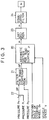
- a pressure sensor 25 is disposed near the discharge port of hydraulic pump 7 as shown in Fig. 1.
- the pressure sensor 25 detects the discharge pressure of hydraulic pump 7.
- the discharge pressure P S of hydraulic pump 7 is supplied to the filter 21 for phase compensation as shown in the block diagram in Fig. 3.
- Step S1 in Fig. 7 the discharge pressure P S is read in place of the pressures P L and P R , and Step S7 in the flowchart in Fig. 8 is bypassed as shown by the broken line.
- Step S4 may decide on only whether the steering wheel 4 is operated or not. In this case, the road surface ⁇ is not calculated when the steering wheel 4 is held at the specified rotational position or it is turned back.
- the coefficients K1, K2 and K3 are corrected so as to be increased as the road surface ⁇ decreases, they may be corrected so that only the equiphase coefficient K1 is increased with decreasing road surface ⁇ .
- the above-described control for advancing the steering phase of front wheels FW is not necessarily needed.
Landscapes
- Engineering & Computer Science (AREA)
- Chemical & Material Sciences (AREA)
- Combustion & Propulsion (AREA)
- Transportation (AREA)
- Mechanical Engineering (AREA)
- Physics & Mathematics (AREA)
- Life Sciences & Earth Sciences (AREA)
- Health & Medical Sciences (AREA)
- Automation & Control Theory (AREA)
- Analytical Chemistry (AREA)
- Biochemistry (AREA)
- General Health & Medical Sciences (AREA)
- General Physics & Mathematics (AREA)
- Immunology (AREA)
- Pathology (AREA)
- Mathematical Physics (AREA)
- Theoretical Computer Science (AREA)
- Steering Control In Accordance With Driving Conditions (AREA)
- Steering-Linkage Mechanisms And Four-Wheel Steering (AREA)
Claims (19)
- Procédé de détection d'un coefficient de frottement d'un revêtement routier sur lequel un véhicule se déplace, le véhicule comprenant des roues avant (FW), un volant (4), et une unité hydraulique (1) de direction assistée disposée entre les roues avant et le volant, l'unité hydraulique de direction assistée assistant le volant pour orienter les roues avant, et le procédé comprenant une étape de détection, qui consiste à détecter un angle de manoeuvre (ϑH) du volant et une vitesse (V) du véhicule, et une étape de calcul qui consiste à calculer un coefficient de frottement (µ) du revêtement routier sur la base de l'angle de manoeuvre et de la vitesse du véhicule détectés,
caractérisé en ce que
ladite étape de calcul inclut:
une première étape de détection d'une pression de fonctionnement (ΔP) de l'unité hydraulique de direction assistée;
une deuxième étape de détection d'une situation appropriée de direction dans laquelle une condition d'augmentation de l'angle d'orientation des roues avant est satisfaite lorsque le volant est manoeuvré; et
une troisième étape de calcul du coefficient de frottement du revêtement routier, sur la base des données détectées à ladite première étape, seulement lorsque la situation appropriée de direction est détectée, le coefficient de frottement du revêtement routier étant calculé en utilisant des relations de trois conditions:(a) un angle de dérapage (βf) des roues avant est déterminé en conformité avec l'angle de manoeuvre du volant, la vitesse du véhicule et le coefficient de frottement du revêtement routier,(b) une force de guidage (Cf) des roues avant est déterminée en fonction de l'angle de dérapage et du coefficient de frottement du revêtement routier, et(c) la force de guidage est proportionnelle à la pression de fonctionnement de l'unité hydraulique de direction assistée. - Procédé selon la revendication 1, caractérisé en ce que la situation est détectée en tant que situation appropriée de direction, à ladite deuxième étape, dès lors qu'est satisfaite, en plus de ladite condition, une condition dans laquelle la valeur absolue de l'angle de manoeuvre du volant n'est pas inférieure à une valeur prédéterminée (ϑ₁).
- Procédé selon la revendication 1, caractérisé en ce que ladite première étape inclut un processus de filtrage (21) pour compenser une avance de phase de la pression de fonctionnement par rapport à l'angle de manoeuvre du volant.
- Procédé selon la revendication 1, caractérisé en ce que l'unité hydraulique de direction assistée comprend des chambres de pression droite et gauche, et une différence de pression (ΔP) entre les chambres de pression droite et gauche est détectée en tant que pression de fonctionnement de l'unité hydraulique de direction assistée.
- Procédé selon la revendication 4, caractérisé en ce que, à ladite deuxième étape, lorsqu'il est satisfait, en plus de ladite condition, à une condition dans laquelle une direction d'orientation des roues avant sur la base d'une direction dans laquelle la pression de fonctionnement se produit est en accord avec une direction d'orientation des roues avant sur la base de l'angle de manoeuvre du volant, cette situation est détectée comme la situation appropriée de direction.
- Procédé selon la revendication 1, caractérisé en ce que, dans ladite troisième étape, lorsque l'angle de manoeuvre du volant obtenu à ladite première étape est désigné par ϑH, la vitesse du véhicule par V et la pression de fonctionnement de l'unité hydraulique de direction assistée par ΔP, le coefficient de frottement µ du revêtement routier est exprimé par


- Procédé selon la revendication 1, caractérisé en ce que le procédé inclut en outre une quatrième étape effectuée après ladite troisième étape, et les première et quatrième étapes sont exécutées de façon répétée, ladite quatrième étape incluant un processus qui consiste à calculer une vitesse de variation (dµ/dt) du coefficient de frottement du revêtement routier sur la base du coefficient de frottement déterminé à ladite troisième étape, et un processus qui consiste à produire le coefficient de frottement du revêtement routier calculé à la dernière troisième étape tel qu'il est lorsque la valeur absolue de la vitesse calculée de variation du coefficient de frottement n'est pas supérieure à une valeur prédéterminée, et à garder et produire le coefficient de frottement du revêtement routier calculé à la troisième étape précédente, lorsque la valeur absolue de celui-ci est supérieure à la valeur prédéterminée.
- Procédé selon la revendication 1, caractérisé en ce que le procédé inclut en outre une cinquième étape, dans laquelle un filtrage (24) est effectué afin de stabiliser le coefficient calculé de frottement du revêtement routier.
- Procédé selon la revendication 1, caractérisé en ce que l'unité hydraulique de direction assistée inclut un vérin (3) de direction disposé entre les roues avant et le volant, une pompe hydraulique (7) destinée à alimenter en fluide hydraulique le vérin de direction et une vanne (5) de direction avant disposée entre la pompe hydraulique et le vérin de direction pour commander une direction d'écoulement du fluide hydraulique depuis la pompe hydraulique jusqu'au vérin de direction et en ce que la pression de fonctionnement de l'unité hydraulique de direction assistée est détectée, à ladite première étape, sur la base de la pression de fluide entre la vanne de direction avant et la pompe hydraulique.
- Procédé selon la revendication 1, caractérisé en ce que, à ladite deuxième étape, lorsqu'il est satisfait soit à ladite condition, soit à une condition dans laquelle le volant est maintenu à une position angulaire au-delà d'une position angulaire prédéterminée, cette situation est détectée comme la situation appropriée de direction.
- Un appareil de détection d'un coefficient de frottement d'un revêtement routier sur lequel le véhicule se déplace, le véhicule comprenant des roues avant (FW), un volant (4) et une unité hydraulique de direction assistée (1) disposée entre les roues avant et le volant, l'unité hydraulique de direction assistée assistant le volant pour orienter les roues avant, et l'appareil comprenant un moyen (16) de détection d'un angle de manoeuvre (ϑH) du volant, un moyen (26) de détection d'une vitesse (V) du véhicule et un moyen (15) d'obtention du coefficient de frottement (µ) du revêtement routier sur la base de l'angle de manoeuvre du volant et de la vitesse du véhicule détectés par lesdits moyens,
caractérisé en ce que
ledit moyen (15) comprend un moyen (18, 19) de détection d'une pression de fonctionnement (ΔP) de l'unité de direction assistée en tant que facteur proportionnel à une force de guidage des roues avant et un moyen de calcul pour calculer le coefficient de frottement du revêtement routier sur la base de l'angle de manoeuvre du volant, de la vitesse du véhicule et de la pression de fonctionnement détectés par lesdits moyens,
ledit moyen de calcul incluant un moyen de détection d'une situation appropriée de direction dans laquelle une condition d'augmentation de l'angle d'orientation des roues avant est satisfaite lorsque le volant est manoeuvré, et un moyen de calcul du coefficient de frottement du revêtement routier en utilisant des relations de trois conditions:(a) un angle de dérapage (βf) des roues avant est déterminé en fonction de l'angle de manoeuvre du volant, de la vitesse du véhicule et du coefficient de frottement sur le revêtement routier,(b) une force de guidage (CF) des roues avant est déterminée en fonction de l'angle de dérapage et du coefficient de frottement du revêtement routier, et(c) la force de guidage est proportionnelle à la pression de fonctionnement de l'unité hydraulique de direction assistée. - Procédé de direction des quatre roues d'un véhicule, le véhicule comprenant un volant (4), des roues avant (FW) orientées par le volant, une unité hydraulique de direction assistée (1) disposée entre les roues avant et le volant, l'unité hydraulique de direction assistée assistant le volant pour orienter les roues avant, et des roues arrière (RW) qui peuvent être orientées en conformité avec l'orientation des roues avant, et ledit procédé comprenant une étape qui consiste à détecter un angle de manoeuvre (ϑH) du volant et une vitesse (V) du véhicule et une étape de calcul qui consiste à calculer un angle d'orientation (δR) des roues arrière sur la base de l'angle détecté de manoeuvre et de la vitesse du véhicule,
caractérisé en ce que
ladite étape de calcul comprend une première étape de détection d'une pression de fonctionnement (ΔP) de l'unité hydraulique de direction assistée, une deuxième étape de détection d'une situation appropriée de direction dans laquelle une condition d'augmentation de l'angle d'orientation des roues avant est satisfaite lorsque le volant est manoeuvré, une troisième étape de calcul d'un coefficient de frottement (µ) du revêtement routier sur la base des données détectées à ladite première étape seulement lorsque la situation appropriée de direction est détectée, et une quatrième étape de calcul d'un angle d'orientation équiphase (δ₁) des roues arrière afin d'orienter les roues arrière dans le même sens que le sens d'orientation des roues avant sur la base de l'angle de manoeuvre du volant et du coefficient de frottement du revêtement routier déterminé à ladite troisième étape lorsque les roues avant sont orientées, l'angle d'orientation équiphase des roues arrière calculé à ladite quatrième étape étant augmenté d'une valeur prédéterminée lorsque le coefficient de frottement du revêtement routier calculé à ladite troisième étape diminue. - Procédé selon la revendication 12, caractérisé en ce que à ladite quatrième étape, une valeur croissante de l'angle d'orientation équiphase des roues arrière est diminuée lorsque la vitesse du véhicule augmente.
- Procédé selon la revendication 13, caractérisé en ce que ladite quatrième étape inclut un processus de préparation d'une carte destinée à la lecture de l'angle d'orientation équiphase des roues arrière, la carte indiquant un coefficient équiphase (K₁) en conformité avec la vitesse du véhicule, et le coefficient équiphase augmentant à partir de zéro au fur et à mesure que la vitesse du véhicule augmente à partir d'une vitesse prédéterminée et se stabilisant à une valeur prédéterminée, et dans lequel ladite quatrième étape inclut en outre un processus de correction de la vitesse du véhicule utilisée pour lire le coefficient équiphase de façon que la vitesse du véhicule augmente lorsque le coefficient de frottement calculé du revêtement routier diminue, et un processus de multiplication de l'angle de manoeuvre du volant par le coefficient équiphase, lu dans la carte en fonction de la vitesse corrigée du véhicule, et ensuite du calcul de l'angle d'orientation équiphase des roues arrière à partir du résultat de la multiplication.
- Procédé selon la revendication 12, caractérisé en ce que ladite quatrième étape inclut un premier processus de calcul d'un angle d'orientation de phase opposée (δ₂) des roues arrière dans le sens opposé au sens d'orientation des roues avant sur la base d'une vitesse angulaire (ΔH) obtenue à partir de l'angle de manoeuvre du volant et du coefficient de frottement du revêtement routier, l'angle d'orientation de phase opposée ainsi calculé étant augmenté lorsque le coefficient de frottement du revêtement routier diminue, et un deuxième processus de calcul final de l'angle d'orientation des roues arrière en ajoutant l'angle d'orientation de phase opposée à l'angle d'orientation en phase des roues arrière.
- Procédé selon la revendication 15, caractérisé en ce que ladite quatrième étape inclut en outre un troisième processus exécuté entre le premier et le deuxième processus, et en ce que, dans le troisième processus, l'angle d'orientation de phase opposée est établi à zéro lorsque l'angle d'orientation de phase opposée calculé n'atteint pas une valeur prédéterminée.
- Procédé selon la revendication 15, caractérisé en ce que le premier processus est un processus de préparation d'une carte de lecture de l'angle d'orientation de phase opposée des roues arrière, la carte indiquant un coefficient (K₂) de phase opposée en conformité avec la vitesse du véhicule, le coefficient de phase opposée étant progressivement augmenté et ensuite progressivement diminué au fur et à mesure que la vitesse du véhicule augmente, et dans lequel le premier processus inclut en outre un processus de correction du coefficient de phase opposée de façon qu'il augmente lorsque le coefficient calculé de frottement du revêtement routier diminue, et un processus de calcul de l'angle d'orientation de phase opposée des roues arrière sur la base de la vitesse angulaire du volant et du coefficient de phase opposée corrigé.
- Procédé selon la revendication 15, caractérisé en ce que le procédé inclut en outre un processus qui consiste à augmenter d'une valeur prédéterminée l'angle d'orientation des roues arrière en conformité avec la vitesse angulaire du volant, la valeur prédéterminée étant augmentée lorsque le coefficient de frottement calculé du revêtement routier diminue.
- Système de de direction des quatre roues d'un véhicule ayant des roues avant et arrière, comprenant un volant (4) pour orienter les roues avant, une unité hydraulique de direction assistée (1) disposée entre les roues avant et le volant, un moyen (16) de détection d'un angle de manoeuvre (ϑH) du volant, un moyen de détection d'une vitesse du véhicule (V), et un moyen d'orientation arrière pour orienter les roues arrière en conformité avec l'angle de manoeuvre du volant lorsque les roues avant sont orientées,
caractérisé en ce que le système inclut en outre un moyen (18, 19) de détection d'une pression de fonctionnement de l'unité hydraulique de direction assistée, et en ce que ledit moyen d'orientation arrière inclut un moyen de détermination d'un angle d'orientation équiphase (δ₁) des roues arrière pour orienter les roues arrière dans le même sens que le sens d'orientation des roues avant sur la base de l'angle de manoeuvre du volant lorsque le volant est manoeuvré, un moyen qui permet de décider, sur la base de l'angle détecté de manoeuvre du volant, s'il est ou non satisfait à une condition dans laquelle le volant est manoeuvré et l'angle d'orientation des roues avant augmente, un moyen de calcul d'un coefficient de frottement (µ) du revêtement routier sur la base de l'angle détecté de manoeuvre du volant, de la vitesse du véhicule et de la pression de fonctionnement seulement lorsque ladite condition est satisfaite, et un moyen de correction de l'angle d'orientation équiphase des roues arrière de façon qu'il augmente au fur et à mesure que le coefficient de frottement calculé du revêtement routier diminue.
Applications Claiming Priority (2)
| Application Number | Priority Date | Filing Date | Title |
|---|---|---|---|
| JP2179239A JP2600986B2 (ja) | 1990-07-06 | 1990-07-06 | 後輪の操舵制御方法 |
| JP179239/90 | 1990-07-06 |
Publications (3)
| Publication Number | Publication Date |
|---|---|
| EP0470700A2 EP0470700A2 (fr) | 1992-02-12 |
| EP0470700A3 EP0470700A3 (en) | 1992-06-03 |
| EP0470700B1 true EP0470700B1 (fr) | 1995-09-20 |
Family
ID=16062378
Family Applications (1)
| Application Number | Title | Priority Date | Filing Date |
|---|---|---|---|
| EP91306077A Expired - Lifetime EP0470700B1 (fr) | 1990-07-06 | 1991-07-04 | Méthode et appareillage de détection du coefficient de frottement du revêtement routier, et méthode et système de direction des quatre roues pour des véhicules, utilisant le coefficient de frottement du revêtement routier détecté |
Country Status (5)
| Country | Link |
|---|---|
| US (1) | US5365439A (fr) |
| EP (1) | EP0470700B1 (fr) |
| JP (1) | JP2600986B2 (fr) |
| KR (1) | KR950012268B1 (fr) |
| DE (1) | DE69113171T2 (fr) |
Cited By (1)
| Publication number | Priority date | Publication date | Assignee | Title |
|---|---|---|---|---|
| CN110740922A (zh) * | 2017-07-20 | 2020-01-31 | 株式会社昭和 | 转向控制装置、电动助力转向装置 |
Families Citing this family (58)
| Publication number | Priority date | Publication date | Assignee | Title |
|---|---|---|---|---|
| DE4200997C2 (de) * | 1992-01-16 | 1994-02-03 | Steyr Daimler Puch Ag | Verfahren zur Ermittlung der fahrdynamischen Sicherheitsreserve von Kraftfahrzeugen |
| DE4320478B4 (de) * | 1993-06-21 | 2007-11-15 | Robert Bosch Gmbh | Fahrstabilitätsregler |
| DE4435448B4 (de) * | 1993-10-13 | 2007-10-11 | Volkswagen Ag | Verfahren zur permanenten Ermittlung des Fahrbahnreibwerts |
| DE19548713C1 (de) * | 1995-12-23 | 1997-05-07 | Daimler Benz Ag | Lenkwinkelstelleinrichtung für ein Kraftfahrzeug |
| JPH1159216A (ja) * | 1997-08-26 | 1999-03-02 | Fuji Heavy Ind Ltd | 4輪駆動車の動力配分制御装置 |
| KR20000003072A (ko) * | 1998-06-25 | 2000-01-15 | 오상수 | 각속도센서를 이용한 노면마찰계수 추정방법및 이를 이용한 차량의 전자제어장치 |
| JP3525429B2 (ja) * | 1998-12-25 | 2004-05-10 | トヨタ自動車株式会社 | 操舵制御装置 |
| SE9902036L (sv) * | 1999-06-03 | 2000-07-31 | Jan Folke Wallenius | Förfarande och anordning för att under färd bestämma friktionen mellan vägbanan och ett fordons hjul |
| JP3271952B2 (ja) * | 1999-07-30 | 2002-04-08 | 富士重工業株式会社 | 車両の路面摩擦係数推定装置 |
| US6508102B1 (en) | 1999-08-26 | 2003-01-21 | Aisin Seiki Co., Ltd. | Near real-time friction estimation for pre-emptive vehicle control |
| US6834218B2 (en) | 2001-11-05 | 2004-12-21 | Ford Global Technologies, Llc | Roll over stability control for an automotive vehicle |
| JP2002012160A (ja) * | 2000-06-29 | 2002-01-15 | Fuji Heavy Ind Ltd | 車両の路面摩擦係数推定装置 |
| US6904350B2 (en) | 2000-09-25 | 2005-06-07 | Ford Global Technologies, Llc | System for dynamically determining the wheel grounding and wheel lifting conditions and their applications in roll stability control |
| US7132937B2 (en) | 2000-09-25 | 2006-11-07 | Ford Global Technologies, Llc | Wheel lift identification for an automotive vehicle using passive and active detection |
| US7233236B2 (en) | 2000-09-25 | 2007-06-19 | Ford Global Technologies, Llc | Passive wheel lift identification for an automotive vehicle using operating input torque to wheel |
| US7109856B2 (en) | 2000-09-25 | 2006-09-19 | Ford Global Technologies, Llc | Wheel lifted and grounded identification for an automotive vehicle |
| US6356188B1 (en) | 2000-09-25 | 2002-03-12 | Ford Global Technologies, Inc. | Wheel lift identification for an automotive vehicle |
| FR2826452B1 (fr) * | 2001-06-26 | 2004-01-30 | Peugeot Citroen Automobiles Sa | Procede d'evaluation de l'adherence des roues directrices d'un vehicule sur une voie de circulation, et application |
| US6549842B1 (en) * | 2001-10-31 | 2003-04-15 | Delphi Technologies, Inc. | Method and apparatus for determining an individual wheel surface coefficient of adhesion |
| US6654674B2 (en) | 2001-11-21 | 2003-11-25 | Ford Global Technologies, Llc | Enhanced system for yaw stability control system to include roll stability control function |
| US6591937B2 (en) * | 2001-12-05 | 2003-07-15 | Delphi Technologies, Inc. | Adaptive variable effort power steering system |
| US6556908B1 (en) | 2002-03-04 | 2003-04-29 | Ford Global Technologies, Inc. | Attitude sensing system for an automotive vehicle relative to the road |
| EP1357007B1 (fr) * | 2002-04-23 | 2006-05-17 | Aisin Seiki Kabushiki Kaisha | Dispositif d'estimation de l'adhérence de roue pour un véhicule automobile |
| US6941205B2 (en) | 2002-08-01 | 2005-09-06 | Ford Global Technologies, Llc. | System and method for deteching roll rate sensor fault |
| US7085639B2 (en) | 2002-08-01 | 2006-08-01 | Ford Global Technologies, Llc | System and method for characterizing the road bank for vehicle roll stability control |
| US7194351B2 (en) | 2002-08-01 | 2007-03-20 | Ford Global Technologies, Llc | System and method for determining a wheel departure angle for a rollover control system |
| US7079928B2 (en) | 2002-08-01 | 2006-07-18 | Ford Global Technologies, Llc | System and method for determining a wheel departure angle for a rollover control system with respect to road roll rate and loading misalignment |
| US7003389B2 (en) | 2002-08-01 | 2006-02-21 | Ford Global Technologies, Llc | System and method for characterizing vehicle body to road angle for vehicle roll stability control |
| US7302331B2 (en) | 2002-08-01 | 2007-11-27 | Ford Global Technologies, Inc. | Wheel lift identification for an automotive vehicle |
| US7430468B2 (en) | 2002-08-05 | 2008-09-30 | Ford Global Technologies, Llc | System and method for sensitizing the activation criteria of a rollover control system |
| US6963797B2 (en) | 2002-08-05 | 2005-11-08 | Ford Global Technologies, Llc | System and method for determining an amount of control for operating a rollover control system |
| US6961648B2 (en) | 2002-08-05 | 2005-11-01 | Ford Motor Company | System and method for desensitizing the activation criteria of a rollover control system |
| US20040024505A1 (en) | 2002-08-05 | 2004-02-05 | Salib Albert Chenouda | System and method for operating a rollover control system in a transition to a rollover condition |
| US7085642B2 (en) | 2002-08-05 | 2006-08-01 | Ford Global Technologies, Llc | Method and system for correcting sensor offsets |
| US20040024504A1 (en) | 2002-08-05 | 2004-02-05 | Salib Albert Chenouda | System and method for operating a rollover control system during an elevated condition |
| JP3964771B2 (ja) * | 2002-10-11 | 2007-08-22 | 株式会社豊田中央研究所 | 路面状態推定装置、及び該装置を備えた車両の運動制御装置 |
| JP3940056B2 (ja) * | 2002-10-11 | 2007-07-04 | アイシン精機株式会社 | 路面状態推定装置、及び該装置を備えた車両の運動制御装置 |
| US6662898B1 (en) | 2002-10-16 | 2003-12-16 | Ford Global Technologies, Llc | Tire side slip angle control for an automotive vehicle using steering actuators |
| US6840343B2 (en) * | 2002-10-16 | 2005-01-11 | Ford Global Technologies, Llc | Tire side slip angle control for an automotive vehicle using steering peak seeking actuators |
| US7316288B1 (en) | 2003-01-27 | 2008-01-08 | Polaris Industries Inc. | All terrain vehicle with multiple steering modes |
| US7278511B1 (en) | 2003-01-27 | 2007-10-09 | Polaris Industries Inc. | Controller for steering a vehicle |
| US9162656B2 (en) | 2003-02-26 | 2015-10-20 | Ford Global Technologies, Llc | Active driven wheel lift identification for an automotive vehicle |
| US7239949B2 (en) | 2003-02-26 | 2007-07-03 | Ford Global Technologies, Llc | Integrated sensing system |
| US7653471B2 (en) | 2003-02-26 | 2010-01-26 | Ford Global Technologies, Llc | Active driven wheel lift identification for an automotive vehicle |
| US7136731B2 (en) | 2003-06-11 | 2006-11-14 | Ford Global Technologies, Llc | System for determining vehicular relative roll angle during a potential rollover event |
| US7308350B2 (en) | 2004-05-20 | 2007-12-11 | Ford Global Technologies, Llc | Method and apparatus for determining adaptive brake gain parameters for use in a safety system of an automotive vehicle |
| US7451032B2 (en) | 2004-06-02 | 2008-11-11 | Ford Global Technologies, Llc | System and method for determining desired yaw rate and lateral velocity for use in a vehicle dynamic control system |
| US7640081B2 (en) | 2004-10-01 | 2009-12-29 | Ford Global Technologies, Llc | Roll stability control using four-wheel drive |
| US7668645B2 (en) | 2004-10-15 | 2010-02-23 | Ford Global Technologies | System and method for dynamically determining vehicle loading and vertical loading distance for use in a vehicle dynamic control system |
| US7715965B2 (en) | 2004-10-15 | 2010-05-11 | Ford Global Technologies | System and method for qualitatively determining vehicle loading conditions |
| US7660654B2 (en) | 2004-12-13 | 2010-02-09 | Ford Global Technologies, Llc | System for dynamically determining vehicle rear/trunk loading for use in a vehicle control system |
| US7480547B2 (en) | 2005-04-14 | 2009-01-20 | Ford Global Technologies, Llc | Attitude sensing system for an automotive vehicle relative to the road |
| US7590481B2 (en) | 2005-09-19 | 2009-09-15 | Ford Global Technologies, Llc | Integrated vehicle control system using dynamically determined vehicle conditions |
| US8121758B2 (en) | 2005-11-09 | 2012-02-21 | Ford Global Technologies | System for determining torque and tire forces using integrated sensing system |
| US7600826B2 (en) | 2005-11-09 | 2009-10-13 | Ford Global Technologies, Llc | System for dynamically determining axle loadings of a moving vehicle using integrated sensing system and its application in vehicle dynamics controls |
| CN106184350B (zh) * | 2016-07-08 | 2018-11-09 | 南京航空航天大学 | 一种多模式的四轮转向系统及转向模式控制方法 |
| CN113188997B (zh) * | 2021-04-29 | 2022-06-14 | 华侨大学 | 一种路面摩擦系数的测量方法、装置、设备和存储介质 |
| CN118722854B (zh) * | 2024-09-04 | 2025-01-07 | 张家港长城汽车研发有限公司 | 一种分配整车转角的方法、装置、车辆和存储介质 |
Family Cites Families (20)
| Publication number | Priority date | Publication date | Assignee | Title |
|---|---|---|---|---|
| US4140440A (en) * | 1974-12-30 | 1979-02-20 | Hydraulic Engine Development Group | Internal combustion piston engine-driven piston pump with hydraulic pressure return of combustion piston from BDC |
| JPS60148769A (ja) * | 1984-01-13 | 1985-08-06 | Honda Motor Co Ltd | 車両の操舵装置 |
| FR2558130B1 (fr) * | 1984-01-13 | 1987-07-17 | Honda Motor Co Ltd | Systeme de direction pour vehicules dont les roues arriere sont dirigees en association avec les roues avant |
| DE3409040A1 (de) * | 1984-03-10 | 1985-09-19 | Burkhard Fugmann | Verfahren zur fruehzeitigen erkennung eines abfalles der bodenhaftung bei den laufraedern eines strassenfahrzeuges |
| JPS628872A (ja) * | 1985-07-08 | 1987-01-16 | Mazda Motor Corp | 車両の4輪操舵装置 |
| JPS6259166A (ja) * | 1985-09-09 | 1987-03-14 | Koyo Seiko Co Ltd | 動力舵取装置に於ける操舵力制御装置 |
| JPS62105776A (ja) * | 1985-11-05 | 1987-05-16 | Nissan Motor Co Ltd | コ−ナリングパワ−検出装置 |
| JPH0649446B2 (ja) * | 1985-11-28 | 1994-06-29 | 日本電装株式会社 | 車両の旋回時制動制御装置 |
| US4721176A (en) * | 1986-06-13 | 1988-01-26 | General Motors Corporation | Vehicle traction control system |
| US4836319A (en) * | 1986-07-22 | 1989-06-06 | Nippondenso Co., Ltd. | Steering control apparatus for motor vehicles |
| DE3633153A1 (de) * | 1986-09-30 | 1988-04-07 | Bosch Gmbh Robert | Vorrichtung zur bestimmung der haftreibung zwischen der fahrbahn und den reifen |
| DE3861868D1 (de) * | 1987-02-03 | 1991-04-11 | Toyoda Chuo Kenkyusho Kk | Steuervorrichtung fuer das lenken der raeder eines fahrzeugs. |
| JPH0818571B2 (ja) * | 1987-06-29 | 1996-02-28 | 日産自動車株式会社 | パワ−ステアリングの油圧制御装置 |
| JPH0815851B2 (ja) * | 1987-10-09 | 1996-02-21 | 日産自動車株式会社 | 差動制限装置 |
| JPH0195978A (ja) * | 1987-10-09 | 1989-04-14 | Fuji Heavy Ind Ltd | 自動車の後輪操舵装置 |
| US4940103A (en) * | 1987-10-14 | 1990-07-10 | Hino Jidosha Kogyo Kabushiki Kaisha (Hino Motors, Ltd.) | Power steering system for use in motor vehicle |
| JPH01109173A (ja) * | 1987-10-23 | 1989-04-26 | Jidosha Kiki Co Ltd | 4輪操舵システム |
| US4882693A (en) * | 1987-12-28 | 1989-11-21 | Ford Motor Company | Automotive system for dynamically determining road adhesion |
| DE8802483U1 (de) * | 1988-02-25 | 1988-04-07 | Thyssen-M.A.N. Aufzüge GmbH, 2000 Hamburg | Fahrtreppe oder Fahrsteig |
| US5147008A (en) * | 1988-10-31 | 1992-09-15 | Mitsubishi Jidosha Kogyo Kabushiki Kaisha | Four-wheel vehicle steering apparatus |
-
1990
- 1990-07-06 JP JP2179239A patent/JP2600986B2/ja not_active Expired - Lifetime
-
1991
- 1991-07-04 DE DE69113171T patent/DE69113171T2/de not_active Expired - Fee Related
- 1991-07-04 EP EP91306077A patent/EP0470700B1/fr not_active Expired - Lifetime
- 1991-07-05 US US07/727,232 patent/US5365439A/en not_active Expired - Fee Related
- 1991-07-06 KR KR1019910011452A patent/KR950012268B1/ko not_active Expired - Fee Related
Non-Patent Citations (1)
| Title |
|---|
| PATENT ABSTRACTS OF JAPAN, vol. 11, no. 323 (M-634), 21 October 1987 & JP-A-62105776 (NISSAN MOTOR) 16 May 1987 * |
Cited By (2)
| Publication number | Priority date | Publication date | Assignee | Title |
|---|---|---|---|---|
| CN110740922A (zh) * | 2017-07-20 | 2020-01-31 | 株式会社昭和 | 转向控制装置、电动助力转向装置 |
| CN110740922B (zh) * | 2017-07-20 | 2021-09-17 | 株式会社昭和 | 转向控制装置、电动助力转向装置 |
Also Published As
| Publication number | Publication date |
|---|---|
| EP0470700A3 (en) | 1992-06-03 |
| EP0470700A2 (fr) | 1992-02-12 |
| US5365439A (en) | 1994-11-15 |
| JP2600986B2 (ja) | 1997-04-16 |
| KR920002416A (ko) | 1992-02-28 |
| JPH0478668A (ja) | 1992-03-12 |
| DE69113171T2 (de) | 1996-05-15 |
| KR950012268B1 (ko) | 1995-10-16 |
| DE69113171D1 (de) | 1995-10-26 |
Similar Documents
| Publication | Publication Date | Title |
|---|---|---|
| EP0470700B1 (fr) | Méthode et appareillage de détection du coefficient de frottement du revêtement routier, et méthode et système de direction des quatre roues pour des véhicules, utilisant le coefficient de frottement du revêtement routier détecté | |
| US6640171B2 (en) | Motor vehicle with supplemental rear steering having open and closed loop modes | |
| US5333058A (en) | Yaw motion control device | |
| JP2932589B2 (ja) | 車両の運動制御装置 | |
| KR960005854B1 (ko) | 스티어링 핸들의 중립점추정 방법 | |
| US5402342A (en) | Method for controlling motor vehicle stability | |
| US4794539A (en) | Propulsion control using steering angle and vehicle speed to determine tolerance range | |
| JP5008549B2 (ja) | 路上走行車両用の触覚制御装置 | |
| US6834218B2 (en) | Roll over stability control for an automotive vehicle | |
| US5136507A (en) | System for correctively controlling turning movement of vehicle | |
| JPH092316A (ja) | 車両のヨーイング挙動制御装置 | |
| JPH02226B2 (fr) | ||
| EP1652752B1 (fr) | Correction de l'angle de braquage de véhicule en fonction de l'angle d'Ackerman | |
| EP0350019B1 (fr) | Commande de direction sur les roues arrières pour véhicule | |
| EP0415451B1 (fr) | Commande de direction des roues arrière pour véhicule | |
| JPH09226556A (ja) | 車両の運動制御装置 | |
| US20020022915A1 (en) | Motor vehicle with supplemental rear steering having open and closed loop modes | |
| JP3328010B2 (ja) | 車両の制御装置 | |
| JPH0733036A (ja) | 後輪操舵制御方法 | |
| JP3324347B2 (ja) | 車両の挙動制御装置 | |
| JPH06207951A (ja) | ヨーレートセンサの異常検出装置 | |
| JP2564975B2 (ja) | 路面摩擦係数の検出方法 | |
| KR100751252B1 (ko) | 요우레이트센서를 이용한 기준차속 보정방법 | |
| JP2611426B2 (ja) | 車両状態観測器 | |
| JP2888010B2 (ja) | 車両用キャンバ角制御装置 |
Legal Events
| Date | Code | Title | Description |
|---|---|---|---|
| PUAI | Public reference made under article 153(3) epc to a published international application that has entered the european phase |
Free format text: ORIGINAL CODE: 0009012 |
|
| AK | Designated contracting states |
Kind code of ref document: A2 Designated state(s): DE FR GB |
|
| PUAL | Search report despatched |
Free format text: ORIGINAL CODE: 0009013 |
|
| AK | Designated contracting states |
Kind code of ref document: A3 Designated state(s): DE FR GB |
|
| 17P | Request for examination filed |
Effective date: 19921102 |
|
| 17Q | First examination report despatched |
Effective date: 19940914 |
|
| GRAA | (expected) grant |
Free format text: ORIGINAL CODE: 0009210 |
|
| AK | Designated contracting states |
Kind code of ref document: B1 Designated state(s): DE FR GB |
|
| REF | Corresponds to: |
Ref document number: 69113171 Country of ref document: DE Date of ref document: 19951026 |
|
| ET | Fr: translation filed | ||
| PLBE | No opposition filed within time limit |
Free format text: ORIGINAL CODE: 0009261 |
|
| STAA | Information on the status of an ep patent application or granted ep patent |
Free format text: STATUS: NO OPPOSITION FILED WITHIN TIME LIMIT |
|
| 26N | No opposition filed | ||
| PGFP | Annual fee paid to national office [announced via postgrant information from national office to epo] |
Ref country code: DE Payment date: 20010625 Year of fee payment: 11 |
|
| PGFP | Annual fee paid to national office [announced via postgrant information from national office to epo] |
Ref country code: GB Payment date: 20010704 Year of fee payment: 11 |
|
| PGFP | Annual fee paid to national office [announced via postgrant information from national office to epo] |
Ref country code: FR Payment date: 20010712 Year of fee payment: 11 |
|
| REG | Reference to a national code |
Ref country code: GB Ref legal event code: IF02 |
|
| PG25 | Lapsed in a contracting state [announced via postgrant information from national office to epo] |
Ref country code: GB Free format text: LAPSE BECAUSE OF NON-PAYMENT OF DUE FEES Effective date: 20020704 |
|
| PG25 | Lapsed in a contracting state [announced via postgrant information from national office to epo] |
Ref country code: DE Free format text: LAPSE BECAUSE OF NON-PAYMENT OF DUE FEES Effective date: 20030201 |
|
| GBPC | Gb: european patent ceased through non-payment of renewal fee |
Effective date: 20020704 |
|
| PG25 | Lapsed in a contracting state [announced via postgrant information from national office to epo] |
Ref country code: FR Free format text: LAPSE BECAUSE OF NON-PAYMENT OF DUE FEES Effective date: 20030331 |
|
| REG | Reference to a national code |
Ref country code: FR Ref legal event code: ST |