EP0470792A1 - Procédé d'enregistrement de signaux numériques - Google Patents
Procédé d'enregistrement de signaux numériques Download PDFInfo
- Publication number
- EP0470792A1 EP0470792A1 EP91307181A EP91307181A EP0470792A1 EP 0470792 A1 EP0470792 A1 EP 0470792A1 EP 91307181 A EP91307181 A EP 91307181A EP 91307181 A EP91307181 A EP 91307181A EP 0470792 A1 EP0470792 A1 EP 0470792A1
- Authority
- EP
- European Patent Office
- Prior art keywords
- track
- specific section
- data
- pilot tone
- section
- Prior art date
- Legal status (The legal status is an assumption and is not a legal conclusion. Google has not performed a legal analysis and makes no representation as to the accuracy of the status listed.)
- Withdrawn
Links
Images



Classifications
-
- G—PHYSICS
- G11—INFORMATION STORAGE
- G11B—INFORMATION STORAGE BASED ON RELATIVE MOVEMENT BETWEEN RECORD CARRIER AND TRANSDUCER
- G11B5/00—Recording by magnetisation or demagnetisation of a record carrier; Reproducing by magnetic means; Record carriers therefor
- G11B5/48—Disposition or mounting of heads or head supports relative to record carriers ; arrangements of heads, e.g. for scanning the record carrier to increase the relative speed
- G11B5/58—Disposition or mounting of heads or head supports relative to record carriers ; arrangements of heads, e.g. for scanning the record carrier to increase the relative speed with provision for moving the head for the purpose of maintaining alignment of the head relative to the record carrier during transducing operation, e.g. to compensate for surface irregularities of the latter or for track following
- G11B5/584—Disposition or mounting of heads or head supports relative to record carriers ; arrangements of heads, e.g. for scanning the record carrier to increase the relative speed with provision for moving the head for the purpose of maintaining alignment of the head relative to the record carrier during transducing operation, e.g. to compensate for surface irregularities of the latter or for track following for track following on tapes
-
- G—PHYSICS
- G11—INFORMATION STORAGE
- G11B—INFORMATION STORAGE BASED ON RELATIVE MOVEMENT BETWEEN RECORD CARRIER AND TRANSDUCER
- G11B15/00—Driving, starting or stopping record carriers of filamentary or web form; Driving both such record carriers and heads; Guiding such record carriers or containers therefor; Control thereof; Control of operating function
- G11B15/18—Driving; Starting; Stopping; Arrangements for control or regulation thereof
- G11B15/46—Controlling, regulating, or indicating speed
- G11B15/463—Controlling, regulating, or indicating speed by using pilot tracking tones embedded in binary coded signals, e.g. using DSV/CDS values of coded signals
-
- G—PHYSICS
- G11—INFORMATION STORAGE
- G11B—INFORMATION STORAGE BASED ON RELATIVE MOVEMENT BETWEEN RECORD CARRIER AND TRANSDUCER
- G11B20/00—Signal processing not specific to the method of recording or reproducing; Circuits therefor
- G11B20/10—Digital recording or reproducing
- G11B20/12—Formatting, e.g. arrangement of data block or words on the record carriers
- G11B20/1201—Formatting, e.g. arrangement of data block or words on the record carriers on tapes
- G11B20/1207—Formatting, e.g. arrangement of data block or words on the record carriers on tapes with transverse tracks only
- G11B20/1208—Formatting, e.g. arrangement of data block or words on the record carriers on tapes with transverse tracks only for continuous data, e.g. digitised analog information signals, pulse code modulated [PCM] data
-
- G—PHYSICS
- G11—INFORMATION STORAGE
- G11B—INFORMATION STORAGE BASED ON RELATIVE MOVEMENT BETWEEN RECORD CARRIER AND TRANSDUCER
- G11B20/00—Signal processing not specific to the method of recording or reproducing; Circuits therefor
- G11B20/10—Digital recording or reproducing
- G11B20/14—Digital recording or reproducing using self-clocking codes
- G11B20/1403—Digital recording or reproducing using self-clocking codes characterised by the use of two levels
- G11B20/1423—Code representation depending on subsequent bits, e.g. delay modulation, double density code, Miller code
- G11B20/1426—Code representation depending on subsequent bits, e.g. delay modulation, double density code, Miller code conversion to or from block codes or representations thereof
-
- G—PHYSICS
- G11—INFORMATION STORAGE
- G11B—INFORMATION STORAGE BASED ON RELATIVE MOVEMENT BETWEEN RECORD CARRIER AND TRANSDUCER
- G11B21/00—Head arrangements not specific to the method of recording or reproducing
- G11B21/02—Driving or moving of heads
- G11B21/10—Track finding or aligning by moving the head ; Provisions for maintaining alignment of the head relative to the track during transducing operation, i.e. track following
- G11B21/103—Track finding or aligning by moving the head ; Provisions for maintaining alignment of the head relative to the track during transducing operation, i.e. track following on tapes
-
- G—PHYSICS
- G11—INFORMATION STORAGE
- G11B—INFORMATION STORAGE BASED ON RELATIVE MOVEMENT BETWEEN RECORD CARRIER AND TRANSDUCER
- G11B5/00—Recording by magnetisation or demagnetisation of a record carrier; Reproducing by magnetic means; Record carriers therefor
- G11B5/008—Recording on, or reproducing or erasing from, magnetic tapes, sheets, e.g. cards, or wires
- G11B5/00813—Recording on, or reproducing or erasing from, magnetic tapes, sheets, e.g. cards, or wires magnetic tapes
- G11B5/00847—Recording on, or reproducing or erasing from, magnetic tapes, sheets, e.g. cards, or wires magnetic tapes on transverse tracks
- G11B5/0086—Recording on, or reproducing or erasing from, magnetic tapes, sheets, e.g. cards, or wires magnetic tapes on transverse tracks using cyclically driven heads providing segmented tracks
-
- G—PHYSICS
- G11—INFORMATION STORAGE
- G11B—INFORMATION STORAGE BASED ON RELATIVE MOVEMENT BETWEEN RECORD CARRIER AND TRANSDUCER
- G11B20/00—Signal processing not specific to the method of recording or reproducing; Circuits therefor
- G11B20/10—Digital recording or reproducing
- G11B20/10527—Audio or video recording; Data buffering arrangements
- G11B2020/10537—Audio or video recording
-
- G—PHYSICS
- G11—INFORMATION STORAGE
- G11B—INFORMATION STORAGE BASED ON RELATIVE MOVEMENT BETWEEN RECORD CARRIER AND TRANSDUCER
- G11B21/00—Head arrangements not specific to the method of recording or reproducing
- G11B21/02—Driving or moving of heads
- G11B21/10—Track finding or aligning by moving the head ; Provisions for maintaining alignment of the head relative to the track during transducing operation, i.e. track following
-
- G—PHYSICS
- G11—INFORMATION STORAGE
- G11B—INFORMATION STORAGE BASED ON RELATIVE MOVEMENT BETWEEN RECORD CARRIER AND TRANSDUCER
- G11B2220/00—Record carriers by type
- G11B2220/90—Tape-like record carriers
-
- G—PHYSICS
- G11—INFORMATION STORAGE
- G11B—INFORMATION STORAGE BASED ON RELATIVE MOVEMENT BETWEEN RECORD CARRIER AND TRANSDUCER
- G11B5/00—Recording by magnetisation or demagnetisation of a record carrier; Reproducing by magnetic means; Record carriers therefor
- G11B5/48—Disposition or mounting of heads or head supports relative to record carriers ; arrangements of heads, e.g. for scanning the record carrier to increase the relative speed
- G11B5/58—Disposition or mounting of heads or head supports relative to record carriers ; arrangements of heads, e.g. for scanning the record carrier to increase the relative speed with provision for moving the head for the purpose of maintaining alignment of the head relative to the record carrier during transducing operation, e.g. to compensate for surface irregularities of the latter or for track following
- G11B5/584—Disposition or mounting of heads or head supports relative to record carriers ; arrangements of heads, e.g. for scanning the record carrier to increase the relative speed with provision for moving the head for the purpose of maintaining alignment of the head relative to the record carrier during transducing operation, e.g. to compensate for surface irregularities of the latter or for track following for track following on tapes
- G11B5/588—Disposition or mounting of heads or head supports relative to record carriers ; arrangements of heads, e.g. for scanning the record carrier to increase the relative speed with provision for moving the head for the purpose of maintaining alignment of the head relative to the record carrier during transducing operation, e.g. to compensate for surface irregularities of the latter or for track following for track following on tapes by controlling the position of the rotating heads
Definitions
- the present invention relates to a method of a digital signal recording suited to reproduction of recorded signals with few errors by accurately tracing the recording tracks formed on a recording medium.
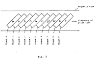
- the frequency of the pilot tone to be superposed on track T1 is supposed to be f1 (Hz), the frequency of the pilot tone to be superposed on track T2 to be f2 (Hz), the frequency of the pilot tone to be superposed on track T3 to be f3 (Hz), and the frequency of the pilot tone to be superposed on track T4 to be f4 (Hz).
- the pilot tone frequencies f1 to f4 are recycled in a period of four tracks, and superposed on each track.
- the tracking is controlled so that the both levels be identical. In other words, it is controlled so that the center of the reproducing head when tracing the track T2 may correctly trace the center of the track T2. Then, by sampling and comparing the crosstalk levels of the both side pilot tones (f2 Hz, f4 Hz) while scanning the track T3, the tracking is controlled so that the both levels be identical. Similarly, while scanning the track T4, the crosstalk levels of the pilot tones (f3 Hz, f1 Hz) are compared to control. While scanning the track T5, the crosstalk levels of the pilot tones (f4 Hz, f2 Hz) are sampled and compared-to control the tracking. The crosstalk of each pilot tone is extracted by a band-pass filter from a reproduced signal.
- the crosstalk level of the pilot tone of such an extent as not to be easily affected by noise must be detected by the bandpass filter to compare the levels.
- the data components of the pertinent frequency may be also regarded as noise. Therefore, the recording level of the pilot tone must be higher than the level of the data signal by about more than ten or more than twenty decibels.
- a pilot tone of such high level is superposed on the data signal analogously, it is equivalent to noise as seen from the data signal, and errors increase in the reproduced data.
- the recording rate increases, thereby making it difficult to record and reproduce.
- the frequency of the pilot tone is set at a relatively low frequency. Therefore, even in the case of azimuth recording, such low frequency component induces a relatively large crosstalk in an adjacent track.
- the signal in the specific section in the track is in DC free state, the signal level near the pilot frequency in this section is sufficiently smaller than the crosstalk level of the pilot tones from the adjacent tracks.
- the DC component of the signal and spectrum of low frequency are lowered in a specific section, if the signal level of the pilot tone to be superposed is low, a necessary crosstalk level is obtained.
- a specific frequency component becomes always large. Therefore, to normally generate a pilot tone having an adequately large level, a special control is necessary after adding the redundant information for this purpose.
- the redundant information to be added is too much, the recording density is high, and if accurate tracking be done, the reproduction error rate increases.
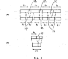
- the invention accordingly, by adding the redundant information only in the specific section in the track, it is intended to generate the pilot tone necessary for tracking only in this section. As a result, accurate tracking is possible without increasing the recording density so much.
- a track is composed of, sequentially from the beginning, a preamble 1, a first burst 2 composed of N1 synchronous blocks, a gap 3, a second burst 4 composed of N2 synchronous blocks, and a postamble 5.
- a synchronous block which is the minimum unit of data processing in block recording is composed of a pattern 6 showing its beginning, an identification symbol 7 of the block, data 8, and parities of error correction code 9.
- parities 11a to 11c of outer codes of K1 lines, and parities 12g to 12i of inner codes relating to the parities 11a to 11c are dispersed as patterns of K2 lines.
- the beginning pattern 6 is added to every inner code word, thereby composing the synchronous block.
- this k1/n conversion code is used for providing the bit stream to be recorded with a characteristic suited to the recording and reproducing system, and finally reducing the bit error rate.
- the parities of inner code corresponds to the parities 9.
- the modulation by k1/n conversion code is actually considered to be modulated by the k2/n modulation code in the portion 13 in which a space of every k1-k2 bits is inserted (shaded area in Fig. 3(e)). This is because the actual information quantity of the data word of k1 bits in which the space SP of k1-k2 bits is inserted, that is, the value taken by the data word, is only for k2 bits.
- DC free state refers to the condition in which the DC components are few in the bit stream to be recorded, and the low frequency components near the DC are also few.
- the feature of such DC free state is that the individual difference of 1 and 0 in the bit stream to be recorded settles within a specific finite value regardless of the type of data.
- the code word to be recorded should be redundant, and the redundancy of the code word is higher in the k2/n conversion code (k1>k2) than in the k1/n conversion code, and the control of DC free state is easier.
- the preamble 1 gap 3, and postamble 5 since the pattern can be set arbitrarily, the DC free pattern can be selected.
- the synchronous block composed of preamble 1, gap 3, postamble 5, and parity symbol of outer code may be set in DC free state.
- FIG. 5 is an explanatory diagram of the composition of data and parities.
- numeral 12b is parity of inner code.
- the composition of the track and synchronous block is same as in the first embodiment.
- the data error correction coding method shown in Fig. 5 is to first apply outer coding in the row direction to the data 10 arranged two-dimensionally (rectangularly) (Fig. 5 (a) ), and parities 11 of outer code are added (Fig. 5(b)).
- the lines 11a to 11c composed of parities of outer code are dispersed among lines 10a to 10d composed of data (Fig. 5 (d) ).
- This space is generated by raising the signal processing rate higher than the blanking period of video signal, and the original data rate.
- the parities 11a to 11c of outer codes of K1 lines are dispersed as patterns of K2 lines.
- the identification symbol 7 is added, and modulation is effected by using k1/n conversion code.
- the parities 12b of the inner code corresponds to the parities 9.
- the synchronous block composed of preamble 1, gap 3, postamble 5, and inspection symbol of outer code may be set in DC free state.
- An example of pattern for setting DC free in the synchronous block composed of preamble 1, gap 3, postamble 5 and parities of outer code, and an example of conversion code for setting DC free in the synchronous block composed of parities of outer code may be same as in the first embodiment.
- a third embodiment of the invention is described below.
- the pilot tone can be inserted digitally.
- C2, C1, C1, C1, C1, C1, C1, C1, C2, C2, C2, C2, C2, C2, C2, C2, C1, C1, C1, C1, C2, ... pilot tones of two types of frequency can be generated.
- preamble, gap and postamble it is advantageous because the recording rate is not increased even when digitally generating pilot tones.
- the modulation with the k2/n conversion code used in the space inserted portion it is possible to generate pilot tones.
- the code words in Table 2 are in pair with the inverted code words obtained by inverting 0 to 1, and 1 to 0, and pilot tones of two different frequencies can be generated by using the pattern obtained by repeating the code word and inverted code word three times each, and the pattern obtained by repeating the code word and inverted code word six times each.
- a pilot tone can be generated from the synchronous block composed of the preamble 1, gap 3, postamble 5, and parities of outer code.
- two patterns are used for preamble and others, and the number of repetitions of code word and inverted code word of 4/12 conversion code is taken as three times and six times, but these are not limitative. Also a pattern capable of generating pilot tones of two or more different frequencies is also possible.
- the error correction code a method of composing DC free block and a method of generating a digital pilot, by using sum codes possessing inner code and outer code are explained, but a similar constitution is also possible for other error correcting code.
- DC free control or pilot tone generation control by using all of parities of outer codes, only a part of the parities may be used.
- instead of composing one synchronous block from one inner code word it is also possible to compose of a plurality of inner code words.
- the number of data bursts provided in one track is not limited to two, but may be other arbitrary number.
- the preamble length, gap length, and postamble length may not necessarily be integer multiples of the synchronous block length.
- Fig. 6 the data 10 arranged two-dimensionally (rectangularly) as shown in Fig. 3(a) by the known art is sent into an outer error encoder 15 sequentially in the row direction, and parities 11 of outer code is added as shown in Fig. 3(b), and is stored in a memory circuit 16.
- the data stored in the memory circuit 16 in the row direction is read out in the line direction, and the data is provided with the parities 12a of the inner code in an inner error encoder, as shown in Fig. 3(c), and is delivered.
- the data is stored in a memory circuit 18 sequentially in the line direction.
- the data is read out in the line direction in the sequence as shown in Fig. 3(d).
- Such reading control is effected in a reading control circuit 19.
- the reading control circuit 19 generates the reading address in the line direction of the memory in the memory circuit 18 so that the output may be obtained as shown in Fig. 3(d), which involves no technical difficulty.
- the output of the memory circuit 18 is recorded in a magnetic tape 22 through a recording circuit 20 composed of amplifier and others, and a recording head 21.
- the reproduction signal from the magnetic tape 22 is stored in a memory circuit 25 through a magnetic head 23, and a reproduction circuit 24 composed of reproduction amplifier and others.
- the output of the reproduction circuit 24 is in the form of Fig. 3(d), and a write control circuit 26 stores the output of the reproduction circuit 24 in the memory circuit 26 in a form of Fig. 3(c).
- This operation is the reverse operation of the read control circuit 19, and the write address in the line direction into the memory in the memory circuit 26 is generated.
- the output from the memory circuit 26 corrects the error in the line direction in an inner error decoder 27, that is, the error in the data in the synchronous block shown in Fig.
- Fig. 3(b) is corrected by using the parities, thereby removing the beginning pattern, identification symbols and parities, and the data is stored in a memory circuit 28 in the form of Fig. 3(b).
- the output of the memory circuit 28 is read in the row direction, and the error in the row direction is corrected by using the parities of outer code in an outer error decoder 29, and the data is delivered in the form being rid of these parities.
- the data is in the two-dimensional (rectangular) form of Fig. 3(a), so that the original data is completely restored.
- Fig. 6 it is explained on the basis that the memory circuits 16, 28 and 19, 26, and the heads 21, 23 are independently provided, but where it is not necessary to record and reproduce simultaneously, these memory circuits and heads can be shared, and the circuit can be reduced.
- Fig. 6 is presented as means for realizing the first embodiment of the invention, but it is evident that the second and third embodiments can be realized by similar circuits.
- the invention realizes tracking of high precision in a very simple circuit constitution, and achieves to lower the error rate.
Landscapes
- Engineering & Computer Science (AREA)
- Signal Processing (AREA)
- Signal Processing For Digital Recording And Reproducing (AREA)
Applications Claiming Priority (2)
| Application Number | Priority Date | Filing Date | Title |
|---|---|---|---|
| JP208606/90 | 1990-08-06 | ||
| JP2208606A JPH0492246A (ja) | 1990-08-06 | 1990-08-06 | ディジタル信号記録方式 |
Publications (1)
| Publication Number | Publication Date |
|---|---|
| EP0470792A1 true EP0470792A1 (fr) | 1992-02-12 |
Family
ID=16558997
Family Applications (1)
| Application Number | Title | Priority Date | Filing Date |
|---|---|---|---|
| EP91307181A Withdrawn EP0470792A1 (fr) | 1990-08-06 | 1991-08-05 | Procédé d'enregistrement de signaux numériques |
Country Status (4)
| Country | Link |
|---|---|
| US (1) | US5317457A (fr) |
| EP (1) | EP0470792A1 (fr) |
| JP (1) | JPH0492246A (fr) |
| KR (1) | KR950006084B1 (fr) |
Cited By (3)
| Publication number | Priority date | Publication date | Assignee | Title |
|---|---|---|---|---|
| EP0608946A3 (en) * | 1993-01-28 | 1995-08-16 | Philips Electronics Nv | Arrangement for recording a video signal and a corresponding audio signal in slant tracks on a longitudinal magnetic record carrier, and record carrier obtained by means of the arrangement. |
| FR2779863A1 (fr) * | 1998-06-16 | 1999-12-17 | Thomson Csf | Systeme de suivi de piste pour l'enregistrement/lecture d'un support d'informations et support d'enregistrement |
| WO2001004879A1 (fr) * | 1999-07-09 | 2001-01-18 | Thales | Systeme de suivi de piste pour l'enregistrement/lecture d'un support d'informations et support d'enregistrement |
Families Citing this family (7)
| Publication number | Priority date | Publication date | Assignee | Title |
|---|---|---|---|---|
| KR100269748B1 (ko) * | 1993-01-30 | 2000-10-16 | 윤종용 | 디지탈 vtr의 영상데이타처리방법 및 그 장치 |
| EP0615236B1 (fr) * | 1993-03-08 | 1999-11-24 | Matsushita Electric Industrial Co., Ltd. | Méthode d'enregistrement de données numériques |
| JP3420286B2 (ja) * | 1993-05-28 | 2003-06-23 | キヤノン株式会社 | 記録再生装置 |
| GB2298078B (en) * | 1995-02-20 | 1998-09-16 | Sony Uk Ltd | Digital tape recorder |
| US5912562A (en) * | 1997-02-04 | 1999-06-15 | Motorola Inc. | Quiescent current monitor circuit for wafer level integrated circuit testing |
| US6662335B1 (en) * | 2000-01-25 | 2003-12-09 | Mediatek Inc. | Method and apparatus for accessing DVD data |
| US12033664B2 (en) | 2022-06-24 | 2024-07-09 | Western Digital Technologies, Inc. | TDS mitigation using different data preamble tones |
Citations (5)
| Publication number | Priority date | Publication date | Assignee | Title |
|---|---|---|---|---|
| US4755893A (en) * | 1985-10-08 | 1988-07-05 | Sony Corporation | Tracking control apparatus using pilot signals and position detecting signals of various lengths |
| US4839755A (en) * | 1986-09-05 | 1989-06-13 | Victor Company Of Japan, Ltd. | Rotary head type digital signal reproducing apparatus with different modes and tracking control |
| EP0339724A1 (fr) * | 1988-04-26 | 1989-11-02 | Koninklijke Philips Electronics N.V. | Dispositif d'enregistrement d'un signal d'information numérique |
| EP0348132A2 (fr) * | 1988-06-24 | 1989-12-27 | Sony Corporation | Méthode et appareil pour la transmission de données |
| US4943873A (en) * | 1986-09-20 | 1990-07-24 | Pioneer Electronic Corporation | Rotary head type digital-audio reproducing device with improved track-deviation detecting system |
Family Cites Families (4)
| Publication number | Priority date | Publication date | Assignee | Title |
|---|---|---|---|---|
| NL8203619A (nl) * | 1982-09-20 | 1984-04-16 | Philips Nv | Werkwijze voor het optekenen van een digitaal informatiesignaal op een registratiedrager, een registratiedrager voorzien van een dergelijk informatiesignaal en een inrichting voor het uitlezen respectievelijk inschrijven van een dergelijke registratiedrager. |
| JPS6318565A (ja) * | 1986-07-11 | 1988-01-26 | Pioneer Electronic Corp | デジタル信号記録再生装置 |
| US5088077A (en) * | 1988-11-10 | 1992-02-11 | Ampex Corporation | Synchronization of record media transports and tracking adjustment |
| JP2768759B2 (ja) * | 1989-10-12 | 1998-06-25 | キヤノン株式会社 | 情報記録再生方法 |
-
1990
- 1990-08-06 JP JP2208606A patent/JPH0492246A/ja active Pending
-
1991
- 1991-08-05 EP EP91307181A patent/EP0470792A1/fr not_active Withdrawn
- 1991-08-06 US US07/741,048 patent/US5317457A/en not_active Expired - Fee Related
- 1991-08-06 KR KR1019910013567A patent/KR950006084B1/ko not_active Expired - Fee Related
Patent Citations (5)
| Publication number | Priority date | Publication date | Assignee | Title |
|---|---|---|---|---|
| US4755893A (en) * | 1985-10-08 | 1988-07-05 | Sony Corporation | Tracking control apparatus using pilot signals and position detecting signals of various lengths |
| US4839755A (en) * | 1986-09-05 | 1989-06-13 | Victor Company Of Japan, Ltd. | Rotary head type digital signal reproducing apparatus with different modes and tracking control |
| US4943873A (en) * | 1986-09-20 | 1990-07-24 | Pioneer Electronic Corporation | Rotary head type digital-audio reproducing device with improved track-deviation detecting system |
| EP0339724A1 (fr) * | 1988-04-26 | 1989-11-02 | Koninklijke Philips Electronics N.V. | Dispositif d'enregistrement d'un signal d'information numérique |
| EP0348132A2 (fr) * | 1988-06-24 | 1989-12-27 | Sony Corporation | Méthode et appareil pour la transmission de données |
Cited By (3)
| Publication number | Priority date | Publication date | Assignee | Title |
|---|---|---|---|---|
| EP0608946A3 (en) * | 1993-01-28 | 1995-08-16 | Philips Electronics Nv | Arrangement for recording a video signal and a corresponding audio signal in slant tracks on a longitudinal magnetic record carrier, and record carrier obtained by means of the arrangement. |
| FR2779863A1 (fr) * | 1998-06-16 | 1999-12-17 | Thomson Csf | Systeme de suivi de piste pour l'enregistrement/lecture d'un support d'informations et support d'enregistrement |
| WO2001004879A1 (fr) * | 1999-07-09 | 2001-01-18 | Thales | Systeme de suivi de piste pour l'enregistrement/lecture d'un support d'informations et support d'enregistrement |
Also Published As
| Publication number | Publication date |
|---|---|
| KR950006084B1 (ko) | 1995-06-08 |
| US5317457A (en) | 1994-05-31 |
| JPH0492246A (ja) | 1992-03-25 |
Similar Documents
| Publication | Publication Date | Title |
|---|---|---|
| KR100263686B1 (ko) | 부호화 방식 | |
| US4905100A (en) | Magnetic recorder/reproducer | |
| RU2089045C1 (ru) | Дешифратор импульсных последовательностей | |
| KR100285127B1 (ko) | 오류정정 부호화방법 및 장치, 오류정정 복호화방법 및 장치,데이터 기록·재생장치, 및 기억매체 | |
| US6861965B2 (en) | Code modulating method and code modulating apparatus, demodulating method and demodulating apparatus, and information recording medium | |
| EP0123563A2 (fr) | Procédé et dispositif de conversion de signaux numériques | |
| EP0470792A1 (fr) | Procédé d'enregistrement de signaux numériques | |
| EP0615382B1 (fr) | Appareil d'enregistrement de signaux digitaux | |
| US4445216A (en) | System for defeating erroneous correction in a digital signal reproducing apparatus | |
| EP0395125A2 (fr) | Appareil d'enregistrement et de reproduction PCM | |
| JPH01228382A (ja) | 映像信号記録方法 | |
| KR100370517B1 (ko) | 변조방법,기록방법,재생방법,기록및재생장치,기록및재생방법,및재생장치 | |
| EP0551694A1 (fr) | Procédé d'enregistrement d'un signal vidéo numérique | |
| KR960006396B1 (ko) | 디지틀신호 기록방법 | |
| US6334024B1 (en) | Helical scan data recording apparatus and a helical scan data reproducing apparatus | |
| JPH077581B2 (ja) | 回転ヘツド形pcm磁気記録再生装置 | |
| US5455719A (en) | Data recording method in which pilot signal period coincides with cumulative bit disparities of insert data | |
| US5233480A (en) | Magnetic recorder/reproducer | |
| JPH0656700B2 (ja) | エラー防止データを含む複トラックデータパターンが設けられた記録担体用のデコード装置及びそのようなデコード装置を有する再生装置 | |
| KR100235788B1 (ko) | 광디스크 시스템에서 동기 신호를 이용한 dsv 제어장치 | |
| JP2546189B2 (ja) | 回転ヘッド形磁気再生装置及びこれに用いる信号処理回路 | |
| KR0145261B1 (ko) | 디지틀신호기록장치 | |
| JPH1027432A (ja) | ディジタル記録再生装置 | |
| JPS59177706A (ja) | 回転ヘツド形pcm磁気記録再生装置 | |
| JPH03154244A (ja) | 固定長記録符号語の記録方法 |
Legal Events
| Date | Code | Title | Description |
|---|---|---|---|
| PUAI | Public reference made under article 153(3) epc to a published international application that has entered the european phase |
Free format text: ORIGINAL CODE: 0009012 |
|
| AK | Designated contracting states |
Kind code of ref document: A1 Designated state(s): DE FR GB NL |
|
| 17P | Request for examination filed |
Effective date: 19920811 |
|
| 17Q | First examination report despatched |
Effective date: 19950206 |
|
| STAA | Information on the status of an ep patent application or granted ep patent |
Free format text: STATUS: THE APPLICATION IS DEEMED TO BE WITHDRAWN |
|
| 18D | Application deemed to be withdrawn |
Effective date: 19950617 |