EP0470826B1 - Système d'enregistrement magnéto-optique - Google Patents
Système d'enregistrement magnéto-optique Download PDFInfo
- Publication number
- EP0470826B1 EP0470826B1 EP91307253A EP91307253A EP0470826B1 EP 0470826 B1 EP0470826 B1 EP 0470826B1 EP 91307253 A EP91307253 A EP 91307253A EP 91307253 A EP91307253 A EP 91307253A EP 0470826 B1 EP0470826 B1 EP 0470826B1
- Authority
- EP
- European Patent Office
- Prior art keywords
- magnetic field
- recording
- magneto
- external magnetic
- recording medium
- Prior art date
- Legal status (The legal status is an assumption and is not a legal conclusion. Google has not performed a legal analysis and makes no representation as to the accuracy of the status listed.)
- Expired - Lifetime
Links
Images


Classifications
-
- G—PHYSICS
- G11—INFORMATION STORAGE
- G11B—INFORMATION STORAGE BASED ON RELATIVE MOVEMENT BETWEEN RECORD CARRIER AND TRANSDUCER
- G11B11/00—Recording on or reproducing from the same record carrier wherein for these two operations the methods are covered by different main groups of groups G11B3/00 - G11B7/00 or by different subgroups of group G11B9/00; Record carriers therefor
- G11B11/10—Recording on or reproducing from the same record carrier wherein for these two operations the methods are covered by different main groups of groups G11B3/00 - G11B7/00 or by different subgroups of group G11B9/00; Record carriers therefor using recording by magnetic means or other means for magnetisation or demagnetisation of a record carrier, e.g. light induced spin magnetisation; Demagnetisation by thermal or stress means in the presence or not of an orienting magnetic field
- G11B11/105—Recording on or reproducing from the same record carrier wherein for these two operations the methods are covered by different main groups of groups G11B3/00 - G11B7/00 or by different subgroups of group G11B9/00; Record carriers therefor using recording by magnetic means or other means for magnetisation or demagnetisation of a record carrier, e.g. light induced spin magnetisation; Demagnetisation by thermal or stress means in the presence or not of an orienting magnetic field using a beam of light or a magnetic field for recording by change of magnetisation and a beam of light for reproducing, i.e. magneto-optical, e.g. light-induced thermomagnetic recording, spin magnetisation recording, Kerr or Faraday effect reproducing
- G11B11/10595—Control of operating function
-
- G—PHYSICS
- G11—INFORMATION STORAGE
- G11B—INFORMATION STORAGE BASED ON RELATIVE MOVEMENT BETWEEN RECORD CARRIER AND TRANSDUCER
- G11B11/00—Recording on or reproducing from the same record carrier wherein for these two operations the methods are covered by different main groups of groups G11B3/00 - G11B7/00 or by different subgroups of group G11B9/00; Record carriers therefor
- G11B11/10—Recording on or reproducing from the same record carrier wherein for these two operations the methods are covered by different main groups of groups G11B3/00 - G11B7/00 or by different subgroups of group G11B9/00; Record carriers therefor using recording by magnetic means or other means for magnetisation or demagnetisation of a record carrier, e.g. light induced spin magnetisation; Demagnetisation by thermal or stress means in the presence or not of an orienting magnetic field
- G11B11/105—Recording on or reproducing from the same record carrier wherein for these two operations the methods are covered by different main groups of groups G11B3/00 - G11B7/00 or by different subgroups of group G11B9/00; Record carriers therefor using recording by magnetic means or other means for magnetisation or demagnetisation of a record carrier, e.g. light induced spin magnetisation; Demagnetisation by thermal or stress means in the presence or not of an orienting magnetic field using a beam of light or a magnetic field for recording by change of magnetisation and a beam of light for reproducing, i.e. magneto-optical, e.g. light-induced thermomagnetic recording, spin magnetisation recording, Kerr or Faraday effect reproducing
- G11B11/10502—Recording on or reproducing from the same record carrier wherein for these two operations the methods are covered by different main groups of groups G11B3/00 - G11B7/00 or by different subgroups of group G11B9/00; Record carriers therefor using recording by magnetic means or other means for magnetisation or demagnetisation of a record carrier, e.g. light induced spin magnetisation; Demagnetisation by thermal or stress means in the presence or not of an orienting magnetic field using a beam of light or a magnetic field for recording by change of magnetisation and a beam of light for reproducing, i.e. magneto-optical, e.g. light-induced thermomagnetic recording, spin magnetisation recording, Kerr or Faraday effect reproducing characterised by the transducing operation to be executed
- G11B11/10504—Recording
- G11B11/10508—Recording by modulating only the magnetic field at the transducer
Definitions
- the present invention relates to a magneto-optical recording system comprising a magneto-optical recording device and a magneto-optical recording medium, such as a magneto-optical disk, card or tape.
- the present invention also relates to the method of recording performed by such a system.
- Magneto-optical recording media as rewritable high-capacity optical memory are the focus of attention, and magneto-optical disks have been utilized.
- Information is recorded on a magneto-optical recording medium by raising the temperature of the recording medium with the irradiation of laser light and applying an external magnetic field thereto.
- the information is reproduced by irradiating laser light on the magneto-optical recording medium and detecting the rotating direction of the polarization plane of the reflected light.
- Magneto-optical recording is roughly divided into two types: optical intensity modulation method and magnetic field modulation method.
- optical intensity modulation method the intensity of laser light is modulated while keeping the external magnetic field having a uniform direction and strength.
- the direction of external magnetic field is uniform and bits are recorded along one direction, before recording the direction of magnetization needs to be opposite to the direction of recording.
- magnetic field modulation method the direction of external magnetic field is switched while keeping the laser light of a fixed intensity.
- the external magnetic field generating means is made of an electromagnet composed of a coil wound around a ferrite core, and the magnetization direction is switched in accordance with the direction of a current flowing through the coil.
- a current having high frequencies hardly goes through the coil due to the coil's self-inductance. Therefore, in order to switch the magnetization direction at a high speed, a high voltage needs to be generated at both ends of the coil, preventing the manufacture of a more compact device consuming less power.
- An object of the present invention is to provide a magneto-optical recording system and method which permits reproduced signals of improved quality.
- this invention provides a magneto-optical recording system comprising a magneto-optical recording device and a magneto-optical recording medium, wherein an external magnetic field, which is applied by said device to said medium at a position of irradiation by a light beam is controllably reversed for recording information on the medium by magnetic field modulation, the device comprising means for inhibiting said irradiation when said magnetic field is reversed, the system characterised in that said recording medium is made of rare earth-transition metal composition wherein the ratio of transition metal to rare earth is greater than the ratio thereof for rare earth-transition metal composition in which the compensation temperature is equal to room temperature.
- the preamble of claim 1 reflects the state of the art according to EP-A-0 275 323.
- this invention provides the method for magneto-optical recording of information defined by claim 6.
- the light source stops irradiating the light beam. Therefore, information is always recorded by the application of an external magnetic field having a sufficient strength, yielding reproduced signals of improved quality. Also, the area on the recording medium wherein information is recorded with a low external magnetic field becomes smaller. Thus, even in the case of using a recording medium which presents deteriorated recording characteristics in relation to low external magnetic field, reproduced signals of acceptable quality are obtained.
- reproduced signals of acceptable quality will also be obtained with the use of an external magnetic field applying means which requires a long time to switch the direction of the applied external magnetic field.
- a recording medium of transition metal-rich rare earth-transition metal composition provides a particularly significant improvement in the C/N ratio in recording by magnetic field modulation.
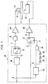
- Fig. 1 illustrates the schematic structure of a magneto-optical recording system according to one embodiment of the present invention.
- Fig 2(a) to Fig. 2(f) are time charts respectively showing the changes of signal at each section of the magneto-optical recording device of Fig. 1.
- Fig. 3 is an explanatory view illustrating the magneto-optical recording device, and the distribution of temperature and coercive force on a recording medium.
- Fig. 4 is an explanatory view illustrating how external magnetic field applying means switches the direction of applied external magnetic field.
- Fig. 5 is an explanatory view illustrating the coercive force distribution on the recording medium used with the magneto-optical recording device of the present invention.
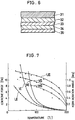
- Fig. 6 is a schematic vertical cross sectional view illustrating a magneto-optical disk used in experiments carried out to test the effects of the present invention.
- Fig. 7 is a graph illustrating the dependence of the coercive force and the Kerr rotation angle upon temperature according to the above experiments.
- Fig. 8 is an explanatory view illustrating the coercive force distribution on a recording medium used with a conventional magneto-optical recording device.
- a magneto-optical recording device for recording information on a magneto-optical disk 11 has a magnetic head 12 as external magnetic field applying means and an optical head 13.
- the magneto-optical disk 11 is composed of a substrate, a vertically magnetized film as recording film, a reflective film and protective film although not shown precisely in the figure.
- the magnetic head 12 is integral with a slider 14 which is capable of sliding over the magneto-optical disk 11, and has the ability to fly. It is pushed towards the disk side by a suspension (not shown), and flies with the rotation of the magneto-optical disk 11.
- the optical head 13 has an optical system composed of a light source, for example semi-conductor laser, and an objective lens (not shown).
- This magneto-optical recording device has a recording signal processing circuit 15 composed of a first circuit and a second circuit. According to a recording signal A, the first circuit and the second circuit generate signals to be supplied to the magnetic head 12 and to the optical head 13, respectively.
- the first circuit has a delay circuit 16, a flip-flop 17, an attenuator 18 and an amplifier 20.
- the recording signal A shown in Fig. 2(a) is inputted to the delay circuit 16, and then a signal B (see Fig. 2(b)) is transmitted after a delay of a specified period.
- the signal B is inputted to a clock input terminal CK of the flip-flop 17, and an output from an inverse output terminal Q ⁇ is inputted to a data input terminal D . Accordingly, from an output terminal Q of the flip-flop 17 is outputted an output C as shown in Fig. 2(c).
- the leading edge of the recording signal A corresponds to the edge of a recording bit.
- An output signal C of the flip-flop 17 is attenuated by the attenuator 18, and then amplified by the amplifier 20.
- An output of the amplifier 20 is supplied to the magnetic head 12.
- an RF amplifier may be used, while when the original data contains a DC component like 2/7 modulation, a DC amplifier may be used.
- the second circuit has a flip-flop 21 serving as control means, a delay circuit 22, three inverters 23, a NAND circuit 24 and an amplifier 25.
- the recording signal A is inputted to a clock input terminal CK of the flip-flop 21, while a signal of a high level is regularly inputted to a data input terminal D thereof.
- the recording signal A is also inputted to the delay circuit 22.
- An output signal E (see Fig. 2 (d)) delayed a predetermined time in the delay circuit 22 is outputted to one of the input terminals of the NAND circuit 24.
- the output signal E is delayed a predetermined time and inverted by three inverters 23, and then supplied to the other input terminal of the NAND circuit 24.
- the NAND circuit 24 transmits an output signal F as shown in Fig. 2(e), and it is inputted to a clear input terminal CL of the flip-flop 21.
- the delay circuit 22 determines a period during which the optical head 13 stops the irradiation of light beam.
- the signal to be supplied to the optical head 13 becomes a low level immediately before the signal to be supplied to the magnetic head 12 is inverted.
- the light source of the optical head 13 is turned off when inverting the magnetic field of the magnetic head 12, so the irradiation of light beam from the light source is stopped.
- This arrangement causes the area, wherein information is recorded with a low external magnetic field, to be smaller, permitting reproduced signals of improved quality.
- the recording film 1 of the magneto-optical disk is normally formed on the substrate 2.
- Information is recorded through the following steps: irradiating a light beam 4 on the recording film 1 through the objective lens 3 while moving (rotating) the recording film 1 in the direction of arrow J; and simultaneously applying an external magnetic field upwards or downwards with the external magnetic field applying means 5 composed of the magnetic head, etc.
- Curved line I in Fig. 3 illustrates the temperature distribution on the recording film 1 with respect to the irradiation of the light beam 4. Meanwhile, curved line II shows the coercive force distribution on the recording film 1.
- the coercive force becomes substantially "0" near the center of the light beam 4, heated to the vicinity of the Curie point.
- an external magnetic field H ex from the external magnetic field applying means 5 exceeds a coercive force H c , information is recorded on the recording film 1.
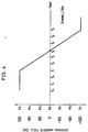
- Fig. 4 shows the relationship between the external magnetic field and the elapse of time when the direction of the external magnetic field is switched by the external magnetic field applying means 5.
- the external magnetic field before switching is H 1 (for example, 120 [Oe])
- the switching starts from time T 1
- the coercive force reaches "0" at time T 4
- one scale on the horizontal line for example, the division between T 0 and T 1 is 3 [nsec].
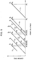
- Fig. 8 shows the relationship between points on track (horizontal line, expressed in nanometer) and the coercive force (vertical line) on the recording film 1 of a conventional magneto-optical recording device by taking time as parameter.
- the track on the recording film 1 moves towards the right and relatively the light beam 4 moves towards the left.
- the coercive force is zero at all the points located left side the crossing point P 1 ′ of a straight line L 1 and the horizontal line, while the coercive force at point located right side of the crossing point P 1 ′ becomes higher towards the far right as approximately shown by the straight line L 1 .
- the external magnetic field at time T 1 is H 1 .
- information is recorded in an area on the recording film 1 where the external magnetic field H 1 exceeds the coercive force H c .
- a recording bit is formed in an area located left side the crossing point P 1 on the track of the external magnetic field H 1 and the straight line L 1 .
- recording bits are formed in areas located left side the crossing points P 2 to P 7 of straight lines L 2 to L 7 and external magnetic fields H 2 to H 7 , respectively. Further, as time elapses, the straight lines L 2 to L 7 indicating coercive force shift towards the left in the figure at a constant speed equal to the relative moving speed of the light beam 4 with respect to the recording film 1.
- the present invention arranges the irradiation of the light beam 4 to be stopped when switching the direction of applying external magnetic field.
- the timing of stopping the irradiation may be controlled as described below.
- information is recorded in an area ranging from P 3 to P 6 with low external magnetic fields H 2 to H 6 , and the area is considerably small compared to an area ranging from P 2 to P 6 shown in Fig. 8.
- information is recorded in a recording area ranging from P 2 to P 4 (Fig. 8) with low external magnetic field before inverting external magnetic field, while in the present invention information in recorded in a reduced area ranging from P 3 to P 4 (Fig. 5). This enables the quality of reproduced signals to improve.
- a magneto-optical recording medium of four-layer structure having a DyFeCo film that is a thin film made of an alloy of rare earth elements and transition metals as magnetic layer and a reflective film, was used in the experiment.
- the structure is illustrated in Fig. 6.
- the magneto-optical recording medium has a transparent substrate 31 made of a polycarbonate plate having 86 mm in outer diameter, 15 mm in inner diameter and 1.5 mm in thickness.
- An AlN film 32 that is a first transparent dielectric film of 80 nm in thickness is formed on the transparent substrate 31.
- a DyFeCo film 33 that is a thin film made of an alloy of rare earth elements and transition metals with 20 nm in thickness is formed on the AlN film 32.
- An AlN film 34 that is a second transparent dielectric film of 25 nm in thickness is formed on the DyFeCo film 33.
- An Al film 35 that is a reflective film with 30 nm in thickness is formed on the AlN film 34.
- the media were respectively produced from substances, Dy X (Fe Y Co (1-Y) ) (1-X) constituting the DyFeCo film 33, wherein the amount X of Dy varies from each other.
- Table 1 and Fig. 7 show the Curie temperature T c , and the dependence of coercive force and Kerr rotation angle upon temperature, measured with respect to the media U, V and W .
- the amount Y of Fe and Co was set at 0.78.
- the composition of the medium V is arranged such that room temperature equals a magnetic compensation temperature.
- the medium U it has a composition containing an increased amount of transition metals compared to the medium V (hereinafter referred to as TM rich ).
- composition of the medium W contains a relatively large amount of rare earth element compared to the medium V (hereinafter referred to as RE rich ).
- RE rich the composition of the medium W contains a relatively large amount of rare earth element compared to the medium V (hereinafter referred to as RE rich ).
- Curved lines UI, VI, and WI in Fig. 7 respectively represent the dependence of the coercive force of the media U, V and W upon temperature. According to this figure, the coercive force decreases as the temperature of the medium comes close to the Curie temperature and also as the amount of Dy decreases. In the meantime, curved lines UII, VII and WII in Fig. 7 show the dependence of the Kerr rotation angle of the respective media U , V and W upon temperature. The Kerr rotation angle becomes smaller as the temperature of the recording medium rises and also as the amount of Dy increases.
- the optical head used for measuring the recording and reproducing characteristics has a semi-conductor laser as light source whose wavelength is 780 nm and an objective lens whose numerical aperture is 0.55.
- the magnetic head of flying type is installed opposite to the optical head with the magneto-optical recording medium between. This head requires about 20 nsec to 30 nsec for switching magnetic field from positive to negative or vice versa.
- the recording and reproducing characteristics with respect to the above three types of media U, V and W shown in Table 1 and Fig. 7 were measured under the following conditions.
- the above optical head and magnetic head were used, the magneto-optical recording medium was controlled to rotate at a linear velocity of 6.3 m/sec and the recording frequency was set such that the length of a recording bit was equal to 0.9 ⁇ m.
- optical intensity modulation recording laser light for recording is modulated while using a unidirectional external magnetic field, in which overwriting is infeasible.
- magnetic field modulation recording external magnetic field is modulated while using recording laser light of a uniform intensity.
- Table 2 shows the comparison in the quality, C/N, of reproduced signals between respective recording methods and recording media, wherein the external magnetic field H e equals ⁇ 100 [Oe].
- the recording laser power, laser pulse length, phase of external magnetic field and of laser pulse in recording were set so as to yield the maximum C/N with the respective recording methods and the recording media.
- the C/N reached the maximum level when the recording laser power was about 5.5 [mW].
- the C/N was the maximum level when the recording laser power was about 6.5 [mW].
- Table 2 indicates that the recording method achieves an improved C/N with respect to any media U , V and W compared to the conventional recording of magnetic field modulation. Particularly, the C/N was significantly improved when the medium U of TM rich composition was used.
- the TM rich composition is used for recording medium when the recording system or method of the present invention is employed. In addition, this yields very favorable characteristics even when the strength of external magnetic field is relatively low, around ⁇ 100 [Oe].
- the recording method of the present invention has the following effects: (i) achieving an improved C/N compared to the one in the conventional recording method of magnetic field modulation; (ii) permitting a wider range of composition of the recording medium compared to the one in the conventional recording method of magnetic field modulation; and (iii) enabling the recording to be performed with an external magnetic field whose strength is lower than the strength of an external magnetic field used in the conventional magnetic field modulation. Consequently, the magnetic head is not required to have a high performance, thereby permitting the manufacture of a more compact device consuming less power.
- the magneto-optical recording device of the present invention also has a reproducing function; it reproduces information from the magneto-optical disk 11.
- the optical head 13 irradiates laser light on the magneto-optical disk 11 and detects the rotation of the polarization plane of the reflected light.
- the explanation is made by using the magneto-optical disk 11 as recording medium.
- the present invention is also applicable to other media, such as magneto-optical cards and tapes.
Claims (6)
- Système d'enregistrement magnéto-optique comportant un dispositif d'enregistrement magnéto-optique (12 à 15) et un support d'enregistrement magnéto-optique (11), dans lequel on peut commander l'inversion d'un champ magnétique externe, appliqué par ledit dispositif audit support au niveau d'une position d'illumination par un faisceau lumineux, pour enregistrer des informations sur le support par modulation de champ magnétique, le dispositif comportant un moyen (21 à 25) pour interrompre ladite illumination au moment de l'inversion dudit champ magnétique, le système étant caractérisé en ce que ledit support d'enregistrement (11) est constitué d'un composé de terres rares et de métaux de transition dans lequel le rapport des métaux de transition aux terres rares est supérieur à celui correspondant à un composé de terres rares et de métaux de transition dans lequel la température de compensation est égale à la température ambiante.
- Système d'enregistrement magnéto-optique selon la revendication 1, dans lequel le dispositif d'enregistrement (12 à 15) comporte:une source lumineuse (13) pour illuminer le support d'enregistrement (11) avec ledit faisceau lumineux;un moyen d'application de champ magnétique externe (12) pour enregistrer des informations sur le support d'enregistrement en appliquant le champ magnétique externe modulé à une zone du support d'enregistrement, la température de la zone étant élevée par l'illumination par le faisceau lumineux; etun moyen de commande (21 à 25) pour faire interrompre par ladite source lumineuse (13) l'illumination par le faisceau lumineux quand ledit moyen d'application de champ magnétique externe (12) inverse la direction du champ magnétique externe appliqué.
- Système d'enregistrement magnéto-optique selon la revendication 2, dans lequel ledit moyen de commande comporte:un circuit à retard (22) à l'entrée duquel est appliqué un signal d'enregistrement (A);trois inverseurs (23) connectés en série à l'entrée desquels est consécutivement appliqué le signal de sortie dudit circuit à retard;un circuit NON-ET (24) ayant deux bornes d'entrée, le signal de sortie dudit circuit à retard étant appliqué à l'une des bornes d'entrée, et le signal de sortie desdits inverseurs étant appliqué à l'autre borne d'entrée;une bascule (21) ayant une borne d'entrée d'horloge, une borne d'entrée de données et une borne d'entrée de remise à zéro, le signal d'enregistrement (A) étant appliqué à ladite borne d'entrée d'horloge, un signal de niveau élevé étant régulièrement appliqué à ladite borne d'entrée de données, le signal de sortie dudit circuit NON-ET étant appliqué à ladite borne d'entrée de remise à zéro; etun amplificateur (25) à l'entrée duquel est appliqué le signal de sortie généré au niveau de la borne de sortie inversée de ladite bascule;dans lequel l'illumination par le faisceau lumineux est interrompue en fonction du signal provenant dudit amplificateur (25).
- Système d'enregistrement magnéto-optique selon la revendication 3, dans lequel le dispositif d'enregistrement comporte en outre:un circuit à retard (16), à l'entrée duquel est appliqué le signal d'enregistrement (A);une bascule (17) ayant une borne d'entrée d'horloge, une borne de sortie inversée et une borne d'entrée de données, le signal de sortie dudit circuit à retard étant appliqué à la borne d'entrée d'horloge, le signal de sortie généré au niveau de ladite borne de sortie inversée étant appliqué à ladite borne d'entrée de données;un atténuateur (18) à l'entrée duquel est appliqué le signal de sortie généré au niveau de la borne de sortie de ladite bascule; etun amplificateur (20) à l'entrée duquel est appliqué le signal de sortie dudit atténuateur;dans lequel la direction du champ magnétique externe appliqué est inversée en fonction du signal provenant dudit amplificateur (20).
- Système d'enregistrement magnéto-optique selon l'une quelconque des revendications précédentes, dans lequel le composé de terres rares et de métaux de transition dont est constitué le support d'enregistrement (11) est du DyFeCo.
- Procédé d'enregistrement d'informations sur un support d'enregistrement magnéto-optique (11) utilisant un dispositif d'enregistrement magnéto-optique (12 à 15) comportant une source lumineuse (13) pour illuminer le support d'enregistrement avec un faisceau lumineux et un moyen d'application de champ magnétique externe (12) pour enregistrer des informations sur le support d'enregistrement en appliquant un champ magnétique externe modulé à une zone du support d'enregistrement, la température du support d'enregistrement étant élevée par l'illumination par le faisceau lumineux, dans lequel le support d'enregistrement (11) est constitué d'un composé de terres rares et de métaux de transition dans lequel le rapport des métaux de transition aux terres rares est supérieur à celui correspondant à un composé de terres rares et de métaux de transition dans lequel la température de compensation est égale à la température ambiante, le procédé comportant:l'illumination du support d'enregistrement par ladite source lumineuse (13) avec le faisceau lumineux;l'application du champ magnétique externe au support d'enregistrement;l'inversion de la direction du champ magnétique externe appliqué en fonction des informations à enregistrer; etl'interruption de l'illumination par le faisceau lumineux au moment de l'inversion de la direction du champ magnétique externe appliqué.
Applications Claiming Priority (2)
| Application Number | Priority Date | Filing Date | Title |
|---|---|---|---|
| JP2210919A JP2733127B2 (ja) | 1990-08-07 | 1990-08-07 | 光磁気記録装置 |
| JP210919/90 | 1990-08-07 |
Publications (2)
| Publication Number | Publication Date |
|---|---|
| EP0470826A1 EP0470826A1 (fr) | 1992-02-12 |
| EP0470826B1 true EP0470826B1 (fr) | 1996-11-06 |
Family
ID=16597242
Family Applications (1)
| Application Number | Title | Priority Date | Filing Date |
|---|---|---|---|
| EP91307253A Expired - Lifetime EP0470826B1 (fr) | 1990-08-07 | 1991-08-07 | Système d'enregistrement magnéto-optique |
Country Status (5)
| Country | Link |
|---|---|
| US (1) | US5475658A (fr) |
| EP (1) | EP0470826B1 (fr) |
| JP (1) | JP2733127B2 (fr) |
| CA (1) | CA2048499C (fr) |
| DE (1) | DE69123004T2 (fr) |
Families Citing this family (2)
| Publication number | Priority date | Publication date | Assignee | Title |
|---|---|---|---|---|
| JP2617025B2 (ja) * | 1990-08-11 | 1997-06-04 | シャープ株式会社 | 磁気記録媒体とその記録再生方法 |
| US20020019938A1 (en) * | 2000-08-04 | 2002-02-14 | Aarons Michael Thomas | Method and apparatus for secure identification for networked environments |
Citations (2)
| Publication number | Priority date | Publication date | Assignee | Title |
|---|---|---|---|---|
| EP0275323A1 (fr) * | 1986-07-31 | 1988-07-27 | Sony Corporation | Appareil d'enregistrement photomagnetique |
| EP0321027A2 (fr) * | 1987-12-14 | 1989-06-21 | Koninklijke Philips Electronics N.V. | Procédé d'enregistrement d'information sur un support thermomagnétique et dispositif pour réaliser le procédé |
Family Cites Families (15)
| Publication number | Priority date | Publication date | Assignee | Title |
|---|---|---|---|---|
| JPS60236137A (ja) * | 1984-05-08 | 1985-11-22 | Nippon Kogaku Kk <Nikon> | 同時消録型光磁気記録方式並びにそれに使用する記録装置及び記録媒体 |
| EP0196590B1 (fr) * | 1985-03-27 | 1992-05-20 | Sony Corporation | Appareil d'enregistrement et de reproduction de signal pour un disque optomagnétique |
| JPS62134838A (ja) * | 1985-12-05 | 1987-06-17 | Matsushita Electric Ind Co Ltd | 光磁気デイスク情報記録再生装置 |
| JPH0721897B2 (ja) * | 1986-04-24 | 1995-03-08 | インタ−ナショナル ビジネス マシ−ンズ コ−ポレ−ション | 光磁気データ記録装置 |
| JPS63187439A (ja) * | 1987-01-30 | 1988-08-03 | Hitachi Ltd | 光磁気記録方式 |
| US4982389A (en) * | 1987-01-30 | 1991-01-01 | Hitachi, Ltd. | Magneto-optical recorder with compensation for variation in applied magnetic field intensity on a recording medium |
| AU600576B2 (en) * | 1987-04-24 | 1990-08-16 | Sony Corporation | Thermomagnetic recording method applying power modulated laser on a magnetically coupled multi-layer structure of perpendicular anisotropy magnetic film |
| EP0312143B1 (fr) * | 1987-10-14 | 1993-08-18 | Koninklijke Philips Electronics N.V. | Dispositif d'enregistrement magnéto-optique et circuit d'activation utilisé dans un tel dispositif d'enregistrement magnéto-optique |
| JP2637191B2 (ja) * | 1988-10-20 | 1997-08-06 | 株式会社リコー | 光磁気記録再生装置の光磁気記録方法 |
| JP2853808B2 (ja) * | 1989-04-13 | 1999-02-03 | シャープ株式会社 | 磁気光学記憶素子 |
| US5172364A (en) * | 1989-08-01 | 1992-12-15 | Mitsubishi Denki Kabushiki Kaisha | Magneto-optic recording apparatus with controlled magnetic field generation |
| JPH03127347A (ja) * | 1989-10-13 | 1991-05-30 | Internatl Business Mach Corp <Ibm> | 光磁気記録方法及び装置 |
| JPH07118106B2 (ja) * | 1990-03-08 | 1995-12-18 | パイオニア株式会社 | 光磁気記録再生装置 |
| JPH0690976B2 (ja) * | 1990-10-05 | 1994-11-14 | インターナショナル・ビジネス・マシーンズ・コーポレーション | 光磁気記録媒体 |
| JP2910250B2 (ja) * | 1990-12-27 | 1999-06-23 | ソニー株式会社 | 光磁気記録媒体 |
-
1990
- 1990-08-07 JP JP2210919A patent/JP2733127B2/ja not_active Expired - Lifetime
-
1991
- 1991-08-06 CA CA002048499A patent/CA2048499C/fr not_active Expired - Lifetime
- 1991-08-07 DE DE69123004T patent/DE69123004T2/de not_active Expired - Lifetime
- 1991-08-07 EP EP91307253A patent/EP0470826B1/fr not_active Expired - Lifetime
-
1994
- 1994-10-07 US US08/320,135 patent/US5475658A/en not_active Expired - Lifetime
Patent Citations (2)
| Publication number | Priority date | Publication date | Assignee | Title |
|---|---|---|---|---|
| EP0275323A1 (fr) * | 1986-07-31 | 1988-07-27 | Sony Corporation | Appareil d'enregistrement photomagnetique |
| EP0321027A2 (fr) * | 1987-12-14 | 1989-06-21 | Koninklijke Philips Electronics N.V. | Procédé d'enregistrement d'information sur un support thermomagnétique et dispositif pour réaliser le procédé |
Also Published As
| Publication number | Publication date |
|---|---|
| EP0470826A1 (fr) | 1992-02-12 |
| DE69123004T2 (de) | 1997-03-27 |
| CA2048499C (fr) | 1999-11-09 |
| JP2733127B2 (ja) | 1998-03-30 |
| CA2048499A1 (fr) | 1992-02-08 |
| US5475658A (en) | 1995-12-12 |
| DE69123004D1 (de) | 1996-12-12 |
| JPH0492237A (ja) | 1992-03-25 |
Similar Documents
| Publication | Publication Date | Title |
|---|---|---|
| KR910003935B1 (ko) | 광자기 기록시스템 | |
| US5656385A (en) | Magnetic recording medium and information recording-reproduction method using the same | |
| EP0225141A2 (fr) | Milieu d'enregistrement magnéto-optique | |
| EP0915462A1 (fr) | Support d'enregistrement magneto-optique, procede de reproduction et dispositif de reproduction | |
| EP0600698B1 (fr) | Milieu d'enregistrement magnéto-optique | |
| US5420833A (en) | Magneto-optical recording medium having first and second magnetic layers | |
| US4518657A (en) | Recording medium and recording-reproduction system provided with the recording medium | |
| US6249490B1 (en) | Magneto-optical recording/reproducing method and apparatus | |
| US5493545A (en) | Magnetooptical recording medium with overwrite capabilities and method for using the same | |
| EP0477701A2 (fr) | Milieu d'enregistrement magnéto-optique superpositionable avec une structure à quatre couches | |
| US5321672A (en) | Method of an apparatus for magneto-optically recording information by changing the position or shape or controlling the diameter of reversed domains | |
| JPH07311986A (ja) | 光磁気記録媒体 | |
| KR930008148B1 (ko) | 광자기 기록장치 | |
| JP2850966B2 (ja) | 光磁気記録装置 | |
| EP0470826B1 (fr) | Système d'enregistrement magnéto-optique | |
| US4805043A (en) | Microgap recording using ferrimagnetic medium for magneto-optic playback | |
| JP2642639B2 (ja) | 光磁気記録方法 | |
| EP0593249A2 (fr) | Méthode d'enregistrement d'information magnéto-optique | |
| EP0601856B1 (fr) | Procédé d'enregistrement magnéto-optique | |
| EP0471527B1 (fr) | Procédé et système de reproduction d'information d'un milieu d'enregistrement magnétique | |
| JPH0814900B2 (ja) | 光磁気記録媒体への書き込み方法 | |
| US5323366A (en) | Magneto-optical recording method with switching and maintaining perpendicular magnetization light beam application modes | |
| US20020018404A1 (en) | Magneto-optical recording medium having different magnetic domain radii in recording layer and reproduction layer | |
| JP2869404B2 (ja) | 光磁気記録装置 | |
| KR960016360B1 (ko) | 광자기 기록방법 |
Legal Events
| Date | Code | Title | Description |
|---|---|---|---|
| PUAI | Public reference made under article 153(3) epc to a published international application that has entered the european phase |
Free format text: ORIGINAL CODE: 0009012 |
|
| AK | Designated contracting states |
Kind code of ref document: A1 Designated state(s): DE FR GB IT NL |
|
| 17P | Request for examination filed |
Effective date: 19920331 |
|
| 17Q | First examination report despatched |
Effective date: 19941216 |
|
| GRAH | Despatch of communication of intention to grant a patent |
Free format text: ORIGINAL CODE: EPIDOS IGRA |
|
| GRAH | Despatch of communication of intention to grant a patent |
Free format text: ORIGINAL CODE: EPIDOS IGRA |
|
| GRAA | (expected) grant |
Free format text: ORIGINAL CODE: 0009210 |
|
| AK | Designated contracting states |
Kind code of ref document: B1 Designated state(s): DE FR GB IT NL |
|
| ITF | It: translation for a ep patent filed | ||
| REF | Corresponds to: |
Ref document number: 69123004 Country of ref document: DE Date of ref document: 19961212 |
|
| ET | Fr: translation filed | ||
| PLBE | No opposition filed within time limit |
Free format text: ORIGINAL CODE: 0009261 |
|
| STAA | Information on the status of an ep patent application or granted ep patent |
Free format text: STATUS: NO OPPOSITION FILED WITHIN TIME LIMIT |
|
| 26N | No opposition filed | ||
| REG | Reference to a national code |
Ref country code: GB Ref legal event code: IF02 |
|
| PGFP | Annual fee paid to national office [announced via postgrant information from national office to epo] |
Ref country code: NL Payment date: 20100814 Year of fee payment: 20 |
|
| PGFP | Annual fee paid to national office [announced via postgrant information from national office to epo] |
Ref country code: FR Payment date: 20100824 Year of fee payment: 20 Ref country code: DE Payment date: 20100812 Year of fee payment: 20 Ref country code: IT Payment date: 20100816 Year of fee payment: 20 |
|
| PGFP | Annual fee paid to national office [announced via postgrant information from national office to epo] |
Ref country code: GB Payment date: 20100811 Year of fee payment: 20 |
|
| REG | Reference to a national code |
Ref country code: DE Ref legal event code: R071 Ref document number: 69123004 Country of ref document: DE |
|
| REG | Reference to a national code |
Ref country code: DE Ref legal event code: R071 Ref document number: 69123004 Country of ref document: DE |
|
| REG | Reference to a national code |
Ref country code: NL Ref legal event code: V4 Effective date: 20110807 |
|
| REG | Reference to a national code |
Ref country code: GB Ref legal event code: PE20 Expiry date: 20110806 |
|
| PG25 | Lapsed in a contracting state [announced via postgrant information from national office to epo] |
Ref country code: GB Free format text: LAPSE BECAUSE OF EXPIRATION OF PROTECTION Effective date: 20110806 |
|
| PG25 | Lapsed in a contracting state [announced via postgrant information from national office to epo] |
Ref country code: NL Free format text: LAPSE BECAUSE OF EXPIRATION OF PROTECTION Effective date: 20110807 |
|
| PG25 | Lapsed in a contracting state [announced via postgrant information from national office to epo] |
Ref country code: DE Free format text: LAPSE BECAUSE OF EXPIRATION OF PROTECTION Effective date: 20110808 |