EP0593249A2 - Méthode d'enregistrement d'information magnéto-optique - Google Patents
Méthode d'enregistrement d'information magnéto-optique Download PDFInfo
- Publication number
- EP0593249A2 EP0593249A2 EP93308100A EP93308100A EP0593249A2 EP 0593249 A2 EP0593249 A2 EP 0593249A2 EP 93308100 A EP93308100 A EP 93308100A EP 93308100 A EP93308100 A EP 93308100A EP 0593249 A2 EP0593249 A2 EP 0593249A2
- Authority
- EP
- European Patent Office
- Prior art keywords
- temperature
- magnetic layer
- magnetooptic
- recording
- recording medium
- Prior art date
- Legal status (The legal status is an assumption and is not a legal conclusion. Google has not performed a legal analysis and makes no representation as to the accuracy of the status listed.)
- Granted
Links
Images


Classifications
-
- G—PHYSICS
- G11—INFORMATION STORAGE
- G11B—INFORMATION STORAGE BASED ON RELATIVE MOVEMENT BETWEEN RECORD CARRIER AND TRANSDUCER
- G11B7/00—Recording or reproducing by optical means, e.g. recording using a thermal beam of optical radiation by modifying optical properties or the physical structure, reproducing using an optical beam at lower power by sensing optical properties; Record carriers therefor
- G11B7/12—Heads, e.g. forming of the optical beam spot or modulation of the optical beam
- G11B7/125—Optical beam sources therefor, e.g. laser control circuitry specially adapted for optical storage devices; Modulators, e.g. means for controlling the size or intensity of optical spots or optical traces
- G11B7/126—Circuits, methods or arrangements for laser control or stabilisation
-
- G—PHYSICS
- G11—INFORMATION STORAGE
- G11B—INFORMATION STORAGE BASED ON RELATIVE MOVEMENT BETWEEN RECORD CARRIER AND TRANSDUCER
- G11B11/00—Recording on or reproducing from the same record carrier wherein for these two operations the methods are covered by different main groups of groups G11B3/00 - G11B7/00 or by different subgroups of group G11B9/00; Record carriers therefor
- G11B11/10—Recording on or reproducing from the same record carrier wherein for these two operations the methods are covered by different main groups of groups G11B3/00 - G11B7/00 or by different subgroups of group G11B9/00; Record carriers therefor using recording by magnetic means or other means for magnetisation or demagnetisation of a record carrier, e.g. light induced spin magnetisation; Demagnetisation by thermal or stress means in the presence or not of an orienting magnetic field
- G11B11/105—Recording on or reproducing from the same record carrier wherein for these two operations the methods are covered by different main groups of groups G11B3/00 - G11B7/00 or by different subgroups of group G11B9/00; Record carriers therefor using recording by magnetic means or other means for magnetisation or demagnetisation of a record carrier, e.g. light induced spin magnetisation; Demagnetisation by thermal or stress means in the presence or not of an orienting magnetic field using a beam of light or a magnetic field for recording by change of magnetisation and a beam of light for reproducing, i.e. magneto-optical, e.g. light-induced thermomagnetic recording, spin magnetisation recording, Kerr or Faraday effect reproducing
- G11B11/10502—Recording on or reproducing from the same record carrier wherein for these two operations the methods are covered by different main groups of groups G11B3/00 - G11B7/00 or by different subgroups of group G11B9/00; Record carriers therefor using recording by magnetic means or other means for magnetisation or demagnetisation of a record carrier, e.g. light induced spin magnetisation; Demagnetisation by thermal or stress means in the presence or not of an orienting magnetic field using a beam of light or a magnetic field for recording by change of magnetisation and a beam of light for reproducing, i.e. magneto-optical, e.g. light-induced thermomagnetic recording, spin magnetisation recording, Kerr or Faraday effect reproducing characterised by the transducing operation to be executed
- G11B11/10517—Overwriting or erasing
- G11B11/10519—Direct overwriting, i.e. performing erasing and recording using the same transducing means
-
- G—PHYSICS
- G11—INFORMATION STORAGE
- G11B—INFORMATION STORAGE BASED ON RELATIVE MOVEMENT BETWEEN RECORD CARRIER AND TRANSDUCER
- G11B11/00—Recording on or reproducing from the same record carrier wherein for these two operations the methods are covered by different main groups of groups G11B3/00 - G11B7/00 or by different subgroups of group G11B9/00; Record carriers therefor
- G11B11/10—Recording on or reproducing from the same record carrier wherein for these two operations the methods are covered by different main groups of groups G11B3/00 - G11B7/00 or by different subgroups of group G11B9/00; Record carriers therefor using recording by magnetic means or other means for magnetisation or demagnetisation of a record carrier, e.g. light induced spin magnetisation; Demagnetisation by thermal or stress means in the presence or not of an orienting magnetic field
- G11B11/105—Recording on or reproducing from the same record carrier wherein for these two operations the methods are covered by different main groups of groups G11B3/00 - G11B7/00 or by different subgroups of group G11B9/00; Record carriers therefor using recording by magnetic means or other means for magnetisation or demagnetisation of a record carrier, e.g. light induced spin magnetisation; Demagnetisation by thermal or stress means in the presence or not of an orienting magnetic field using a beam of light or a magnetic field for recording by change of magnetisation and a beam of light for reproducing, i.e. magneto-optical, e.g. light-induced thermomagnetic recording, spin magnetisation recording, Kerr or Faraday effect reproducing
- G11B11/10502—Recording on or reproducing from the same record carrier wherein for these two operations the methods are covered by different main groups of groups G11B3/00 - G11B7/00 or by different subgroups of group G11B9/00; Record carriers therefor using recording by magnetic means or other means for magnetisation or demagnetisation of a record carrier, e.g. light induced spin magnetisation; Demagnetisation by thermal or stress means in the presence or not of an orienting magnetic field using a beam of light or a magnetic field for recording by change of magnetisation and a beam of light for reproducing, i.e. magneto-optical, e.g. light-induced thermomagnetic recording, spin magnetisation recording, Kerr or Faraday effect reproducing characterised by the transducing operation to be executed
- G11B11/1053—Recording on or reproducing from the same record carrier wherein for these two operations the methods are covered by different main groups of groups G11B3/00 - G11B7/00 or by different subgroups of group G11B9/00; Record carriers therefor using recording by magnetic means or other means for magnetisation or demagnetisation of a record carrier, e.g. light induced spin magnetisation; Demagnetisation by thermal or stress means in the presence or not of an orienting magnetic field using a beam of light or a magnetic field for recording by change of magnetisation and a beam of light for reproducing, i.e. magneto-optical, e.g. light-induced thermomagnetic recording, spin magnetisation recording, Kerr or Faraday effect reproducing characterised by the transducing operation to be executed to compensate for the magnetic domain drift or time shift
-
- G—PHYSICS
- G11—INFORMATION STORAGE
- G11B—INFORMATION STORAGE BASED ON RELATIVE MOVEMENT BETWEEN RECORD CARRIER AND TRANSDUCER
- G11B11/00—Recording on or reproducing from the same record carrier wherein for these two operations the methods are covered by different main groups of groups G11B3/00 - G11B7/00 or by different subgroups of group G11B9/00; Record carriers therefor
- G11B11/10—Recording on or reproducing from the same record carrier wherein for these two operations the methods are covered by different main groups of groups G11B3/00 - G11B7/00 or by different subgroups of group G11B9/00; Record carriers therefor using recording by magnetic means or other means for magnetisation or demagnetisation of a record carrier, e.g. light induced spin magnetisation; Demagnetisation by thermal or stress means in the presence or not of an orienting magnetic field
- G11B11/105—Recording on or reproducing from the same record carrier wherein for these two operations the methods are covered by different main groups of groups G11B3/00 - G11B7/00 or by different subgroups of group G11B9/00; Record carriers therefor using recording by magnetic means or other means for magnetisation or demagnetisation of a record carrier, e.g. light induced spin magnetisation; Demagnetisation by thermal or stress means in the presence or not of an orienting magnetic field using a beam of light or a magnetic field for recording by change of magnetisation and a beam of light for reproducing, i.e. magneto-optical, e.g. light-induced thermomagnetic recording, spin magnetisation recording, Kerr or Faraday effect reproducing
- G11B11/10582—Record carriers characterised by the selection of the material or by the structure or form
- G11B11/10584—Record carriers characterised by the selection of the material or by the structure or form characterised by the form, e.g. comprising mechanical protection elements
-
- G—PHYSICS
- G11—INFORMATION STORAGE
- G11B—INFORMATION STORAGE BASED ON RELATIVE MOVEMENT BETWEEN RECORD CARRIER AND TRANSDUCER
- G11B11/00—Recording on or reproducing from the same record carrier wherein for these two operations the methods are covered by different main groups of groups G11B3/00 - G11B7/00 or by different subgroups of group G11B9/00; Record carriers therefor
- G11B11/10—Recording on or reproducing from the same record carrier wherein for these two operations the methods are covered by different main groups of groups G11B3/00 - G11B7/00 or by different subgroups of group G11B9/00; Record carriers therefor using recording by magnetic means or other means for magnetisation or demagnetisation of a record carrier, e.g. light induced spin magnetisation; Demagnetisation by thermal or stress means in the presence or not of an orienting magnetic field
- G11B11/105—Recording on or reproducing from the same record carrier wherein for these two operations the methods are covered by different main groups of groups G11B3/00 - G11B7/00 or by different subgroups of group G11B9/00; Record carriers therefor using recording by magnetic means or other means for magnetisation or demagnetisation of a record carrier, e.g. light induced spin magnetisation; Demagnetisation by thermal or stress means in the presence or not of an orienting magnetic field using a beam of light or a magnetic field for recording by change of magnetisation and a beam of light for reproducing, i.e. magneto-optical, e.g. light-induced thermomagnetic recording, spin magnetisation recording, Kerr or Faraday effect reproducing
- G11B11/10502—Recording on or reproducing from the same record carrier wherein for these two operations the methods are covered by different main groups of groups G11B3/00 - G11B7/00 or by different subgroups of group G11B9/00; Record carriers therefor using recording by magnetic means or other means for magnetisation or demagnetisation of a record carrier, e.g. light induced spin magnetisation; Demagnetisation by thermal or stress means in the presence or not of an orienting magnetic field using a beam of light or a magnetic field for recording by change of magnetisation and a beam of light for reproducing, i.e. magneto-optical, e.g. light-induced thermomagnetic recording, spin magnetisation recording, Kerr or Faraday effect reproducing characterised by the transducing operation to be executed
- G11B11/10504—Recording
- G11B11/10506—Recording by modulating only the light beam of the transducer
-
- G—PHYSICS
- G11—INFORMATION STORAGE
- G11B—INFORMATION STORAGE BASED ON RELATIVE MOVEMENT BETWEEN RECORD CARRIER AND TRANSDUCER
- G11B11/00—Recording on or reproducing from the same record carrier wherein for these two operations the methods are covered by different main groups of groups G11B3/00 - G11B7/00 or by different subgroups of group G11B9/00; Record carriers therefor
- G11B11/10—Recording on or reproducing from the same record carrier wherein for these two operations the methods are covered by different main groups of groups G11B3/00 - G11B7/00 or by different subgroups of group G11B9/00; Record carriers therefor using recording by magnetic means or other means for magnetisation or demagnetisation of a record carrier, e.g. light induced spin magnetisation; Demagnetisation by thermal or stress means in the presence or not of an orienting magnetic field
- G11B11/105—Recording on or reproducing from the same record carrier wherein for these two operations the methods are covered by different main groups of groups G11B3/00 - G11B7/00 or by different subgroups of group G11B9/00; Record carriers therefor using recording by magnetic means or other means for magnetisation or demagnetisation of a record carrier, e.g. light induced spin magnetisation; Demagnetisation by thermal or stress means in the presence or not of an orienting magnetic field using a beam of light or a magnetic field for recording by change of magnetisation and a beam of light for reproducing, i.e. magneto-optical, e.g. light-induced thermomagnetic recording, spin magnetisation recording, Kerr or Faraday effect reproducing
- G11B11/10582—Record carriers characterised by the selection of the material or by the structure or form
- G11B11/10586—Record carriers characterised by the selection of the material or by the structure or form characterised by the selection of the material
Definitions
- the invention relates to a magneooptic information recording method and, more particularly, to a magnetooptic information recording method which can perform an overwriting (overwrite recording) by modulating a light beam.
- a magnetic field modulating method or a light modulating method using a switched connection laminate film shown in Japanese Patent Application Laid-Open No. 62-175948 has hitherto been known.
- the light modulating method is-more advantageous from a viewpoint such that a modulating speed can be raised and a double-sided medium can be used or the like.
- a method of recording to a magnetooptic recording medium (magnetooptic disk) at a high recording density a method whereby information is recorded at both ends of a mark written on the medium, namely, what is called a mark edge recording method is known.
- a size of mark which is formed by the light modulating method depends on a spot diameter of a light beam which is used for recording.
- the spot shape of light beam is almost circular, when a mark of a pitch that is relatively short as compared with a track width is formed, the mark size in the track width direction also decreases.
- the spot diameter of the light which is used for reproduction is equal to about a track width, an amplitude of a reproduction signal from such a mark is smaller than that of the mark formed in the whole track width at the same pitch as that of the above mark, so that there is a problem such that a DC offset increases.
- the above object is accomplished by a magnetooptic information recording method whereby a light beam which was modulated in accordance with a data signal to be recorded is irradiated while moving a magnetooptic recording medium and the magnetooptic recording medium is locally heated or cooled, thereby recording, wherein during a series of recording operations, a predetermined recording area of the magnetooptic recording medium is heated to a temperature of a second temperature T2 or higher in accordance with the data signal and at least a part of the area heated to the temperature of the second temperature T2 or higher is once cooled down to a temperature of a third temperature T3 or lower and, after that, it is heated to a temperature of a first temperature T1 or higher.
- a magnetooptic recording medium which is used in a magnetooptic information recording method of the invention has at least: a first magnetic layer having a Curie temperature T1; and a second magnetic layer which has a Curie temperature T2 higher than T1 and is switching connected with the first magnetic layer.
- the second magnetic layer always has a predetermined magnetizing state at an ambient temperature.
- a binary recording is performed in dependence on whether the magnetizing state of the first magnetic layer has a stable orientation for the second magnetic layer due to the coupling by an exchange force or not. That is, by heating the first magnetic layer to about a temperature exceeding a first temperature T1 from the ambient temperature, the magnetizing state of the first magnetic layer is set to a stable orientation for the second magnetic layer. By cooling those layers down to the ambient temperature, the magnetizing states of the first and second magnetic layers are held.
- One of the recording states of the binary recording in which the first magnetic layer is oriented to the stable state for the second magnetic layer is obtained.
- the second magnetic layer is set to a magnetizing state different from that at the ambient temperature due to an influence by the external magnetic field.
- the magnetizing state of the first magnetic layer also changes (while keeping the stable orientation for the second magnetic layer).
- the magnetizing state of the second magnetic layer changes to the magnetizing state at the ambient temperature without changing the magnetizing state of the first magnetic layer.
- a recording mark in a magnetizing state different from the ambient magnetizing state is formed in the area which was heated to a temperature of the second temperature T2 or higher.
- the second magnetic layer is initialized to a predetermined magnetizing state by the switched connection force of another adjacent magnetic layer or by an external initialization magnetic field.
- the magnetizing state of the first magnetic layer is maintained as it is and the mark is held (recording operation).
- the first magnetic layer is also initialized (stable orientation for the second magnetic layer) in the area at a temperature of the first temperature T1 or higher in the area in which the second magnetic layer was initialized, so that the mark formed is erased (erasing operation). Since the medium is moved, the whole portion of the formed mark is not erased but only the rear portion with respect to the moving direction in the formed mark is erased. Therefore, a mark of a pitch that is relatively shorter than the track width can be stably formed without changing the mark size in the track width direction.
- a difference between the first and third tempertures T1 and T3 is equal to or less than 80°C, more preferably, 40°C or lower and, further more desirably, 20°C or less.
- Third and fourth magnetic layers are sequentially laminated onto the second magnetic layer so as to be neighboring.
- the fourth magnetic layer is formed so that a predetermined magnetizing state can be held in the whole temperature raising and cooling steps upon recording.
- the Curie temperature of the third magnetic layer can be also set to be higher than the Curie temperature of the first magnetic layer.
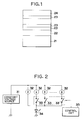
- Fig. 1 is a schematic cross sectional view showing a construction of an embodiment of a magnetooptic recording medium which is used in the invention.
- the magnetooptic recording medium is constructed in a manner such that a plurality of magnetic layers 23 are sequentially laminated through a dielectric layer 22 onto a transparent substrate 21 made by polycarbonate, glass, or the like, and a dielectric layer 24 is again finally laminated as a protective film.
- the dielectric layers 22 and 24 can use a transparent dielectric material such as Si3N4, AlN, SiO2, SiO, ZnS, MgF2, or the like.
- Each of the dielectric layers 22 and 24 and each of the magnetic layers 23 are deposited and formed by a continuous sputtering by, for example, a magnetron sputtering apparatus, a continuous evaporation deposition, or the like. Particularly, by continuous forming the magnetic layers 23 without breaking a vacuum state, they are mutually switching coupled.
- each magnetic layer 23 is made by various magnetic materials.
- each magnetic layer 23 can be formed by a rare earth - iron group amorphous alloy which is constructed by 10 to 40 atom % of one or two or more kinds of rare earth elements such as Pr, Nd, Sm, Gd, Tb, Dy, Ho, etc. and 90 to 60 atom % of one or two or more kinds of iron group elements of Fe, Co, Ni, and the like.
- a small quantity of element such as Cr, Mn, Cu, Ti, Al, Si, Pt, In, etc. can be also added to such an alloy.
- the saturation magnetization of each magnetic layer 23 can be controlled by a composition ratio of the rare earth element and the iron group element.
- the Curie temperature can be also controlled by the composition ratio, in order to control the Curie temperature independently of the saturation magnetization, it is possible to preferably use a method of controlling a substitution amount by using a material in which a part of Fe as an iron group element is substituted to Co. Namely, by substituting one atom % of Fe by Co, there is a prospect of an increase in Curie temperature of about 6°C. Therefore, an addition amount of Co is adjusted by the above relation so as to obtain a desired Curie temperature.
- the Curie temperature can be also contrarily reduced.
- the Curie temperature can be also controlled by using two or more kinds of rare earth elements and by adjusting their composition ratio.
- the magnetic layers 23 will now be further described in detail.
- Two of the magnetic layers 23 are the first and second magnetic layers. With respect to the first and second magnetic layers, the following five conditions are all satisfied.
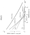
- a laser driving circuit as shown in Fig. 2 is used.
- the laser driving circuit uses a plurality of constant current sources 32 arranged in parallel in order to drive a laser diode 34.
- One end of each of the constant current sources 32 is commonly connected to a constant voltage source 31 and the other end is commonly connected to the laser diode 34 through a switching device 33 provided for every constant current source 32.
- Only one of a plurality of constant current sources 32 is directly connected to a connecting point of the laser diode 34 without using the switching device.
- Each switching device 33 can turn on or off a current at a high speed and is controlled by a control circuit 35.
- a data signal to be recorded and a reference clock (channel clock) are supplied to the control circuit 35.
- a laser driving circuit By using such a laser driving circuit, a laser beam at an output level of a multivalue can be generated at an arbitrary timing in accordance with the recording signal.
- a construction of the other portions of the magnetooptic recording and/or reproducing apparatus is similar to that of the conventional magnetooptic recording and/or reproducing apparatus.
- a fixed permanent magnet can be used as recording bias magnetic field generating means for generating a magnetic field that is applied to the magnetooptic recording medium upon recording.
- a floating magnetic field of the magnetooptic recording medium itself, a leakage magnetic field from an actuator, or the like can be also used according to the circumstances. In such a case, the recording bias magnetic field generating means can be omitted.
- the magnetooptic recording medium which is used in the invention was actually manufactured and the result in the case where the recording was performed in accordance with the recording method of the invention will now be described.
- a layer (dielectric layer) made by silicon nitride having a film thickness of 80 nm was formed by a sputtering method onto a disk-shaped substrate having a diameter of 86 mm on which spiral-shaped tracks having a pitch of 1.6 ⁇ m and a land width of 1.0 ⁇ m were formed.
- Table 1 magnetic multilayer films having a five-layer construction comprising magnetic layers 1 to 5 were sequentially formed onto the dielectric layer without breaking a vacuum state. Subsequently, a dielectric layer made of silicon nitride having a film thickness of 60 nm was formed, thereby manufacturing a magnetooptic recording medium (magnetooptic disk) which can perform the overwriting by the light modulation.
- the magnetic layer 1 corresponds to the first magnetic layer and the magnetic layer 3 corresponds to the second magnetic layer.
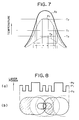
- Fig. 3 shows a temperature dependency of the magnetic characteristics of each magnetic layer in the magnetooptic recording medium.
- the magnetooptic disk is loaded to the above magnetooptic recording/reproducing apparatus and is rotated at a predetermined period of 30 Hz.
- a laser beam modulated as will be explained hereinafter is irradiated to the disk at the position of a radius of 24 mm while applying a downward recording bias magnetic field Hb of 300 Oe, thereby recording.
- a wavelength of laser beam is set to 780 nm.
- a numerical aperture NA of objective lens is set to 0.55.
- the magnetooptic recording medium satisfies the medium conditions of the invention.
- the coercive force energies and Zeeman energies of the magnetic layers 2 and 4 are ignored because they hardly exert an influence on the operation of the magnetization.
- the Bloch magnetic wall energies and diamagnetic field energies are also ignored because of a similar reason.
- the change in orientation of the magnetizing state of each magnetic layer depending on the temperature which has been described here is diagrammatically shown in Fig. 4.
- the magnetic layers 2 and 4 are the magnetic layers (adjusting layers) which are interposed in order to set the magnitudes of ⁇ w13 and ⁇ w35 and the temperature dependencies to desired characteristics as shown in Fig. 3.
- a material of the magnetic layer 2 a material such that a Curie temperature is equal to or higher than about T c1 (T c1 denotes a Curie temperature of the magnetic layer 1) and a magnetic domain wall energy is as small as possible to preferably selected.
- T c1 denotes a Curie temperature of the magnetic layer 1
- a magnetic domain wall energy is as small as possible to preferably selected.
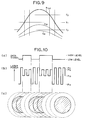
- the modulation laser signal comprises: a portion of a laser power P1 whose duration changes in accordance with the data signal to be recorded; a portion of a laser power P2 whose duration changes in accordance with the data signal subsequently to the portion of P1; and a portion of a laser power P3 whose duration constant subsequently to the portion of P2. After the portion of P3, the portion of the laser power P1 for the next data signal continues.
- the medium When the laser beam of the laser signal whose power changes as shown in (a) in Fig. 6 is irradiated to the magnetooptic recording medium while moving it, the medium is locally heated and its temperature is increased as shown in (b) in Fig. 6 in correspondence to the laser signal.
- a region surrounded by a solid line is heated to a temperature which is equal to or higher than the temperature T2 and an inversion magnetic domain is formed in this region.
- a region surrounded by a broken line is subsequently cooled to a temperature of T3 or lower by radiating the heat and the magnetic layer 3 is initialized.
- a magnetic domain different from the initial state is formed in the hatched portion in (b) in Fig. 6. Namely, a recording mark can be formed at a pitch smaller than the track width.
- Fig. 7 is a diagram showing the relation between the laser power and the temperature distribution in the second embodiment.
- the laser power P1 among the three levels P1 to P3 is set to be higher than that in the first embodiment.
- the temperature of the central portion is slightly higher than T2.
- the third embodiment intends to execute the recording by using laser powers P11 to P14 at four levels.
- Fig. 9 shows temperature distributions t11 to t14 which are caused in correspondence to the laser powers P11 to P14, respectively.
- the largest power level P11 certainly comes.
- the power levels P12 and P13 follow. Therefore, the temperature distributions t11 and t12 corresponding to the power levels P11 and P12 are almost similar and exceed the temperature T2.
- the temperature distribution t13 corresponding to P13 exceeds T3 but doesn't reach T1.
- the temperature distribution t14 corresponding to P14 doesn't exceed T3.
- the recording operation was executed to the magnetooptic recording medium of the first embodiment by using such laser pulses in a manner similar to the first embodiment.
- a laser signal as shown in (b) in Fig. 10 is irradiated to the magnetooptic recording medium in accordance with a data signal a shown in (a) in Fig. 10.
- a data signal a shown in (a) in Fig. 10 By selecting either one of the power levels P13 and P14, whether the recording layer is cooled to a temperature of T3 or lower after completion of the irradiation of the laser pulse or not can be controlled. Therefore, whether the mark formed by one certain pulse is erased by the temperature increase by the next pulse or not can be selected. Therefore, a mark as shown by a hatched region in (c) in Fig. 10 is formed.
- Table 2 Four kinds of magnetic layers shown in Table 2 were sequentially laminated by manufacturing steps similar to those of the magnetooptic recording medium used in the first embodiment. After that, a layer of silicon nitride having a film thickness of 10 nm was formed as a dielectric layer. Further, an aluminum layer having a thickness of 40 nm was subsequently formed, thereby manufacturing a magnetooptic recording medium (magnetooptic disk) which can overwrite by the light modulation. After that, a magnetic field of about 15 kOe was applied to the whole surface of the magnetooptic recording medium. The magnetic layers 3 and 5 were magnetized so that the magnetizing directions are set to the upward directions perpendicular to the film surface. A reason why a film thickness h2 of magnetic layer 2 is equal to 0 in Table 2 is because the magnetic layer 2 is not formed. Consequently, the magnetic layers 1 and 3 are directly in contact with each other.
- a film thickness h2 of magnetic layer 2 is equal to 0 in Table 2 is because the magnetic layer 2 is not formed. Consequently,
- the magnetooptic recording medium was loaded into the magnetooptic recording and/or reproducing apparatus and was rotated at a predetermined period of 60 Hz.
- a laser beam modulated as will be explained hereinlater was irradiated to the medium at the position of a radius of 40 mm while applying the upward recording bias magnetic field Hb of 300 Oe, thereby performing the recording.
- An optical system used for measurement is similar to that in the first embodiment.
- the magnetooptic recording medium a metal layer (aluminum layer here) of a large heat conductivity was added so as to correspond to the high speed recording, thereby raising a thermal response speed.
- the Curie temperature of the magnetic layer 4 is set to be higher than the Curie temperature of the magnetic layer 1
- the first temperature T1 is about 150 to 160°C
- the third temperature T3 is about 140 to 150°C and they are set to close values. Therefore, the medium can be initialized by a temperature that is enough higher than the ambient temperature and a cooling time for initialization can be reduced.
- the magnetizing direction of each of the magnetic layers 3 and 5 is set to the same direction as the direction of the recording bias magnetic field Hb that is applied upon recording.
- the magnetic layer 2 has been provided for adjustment of the interface magnetic wall energy in the first embodiment, such a magnetic layer 2 is omitted in the fourth embodiment. In place of it, after the magnetic layer 1 was formed, it is left for a little while and its surface is purposely polluted and the magnetic layer 3 is laminated after that, thereby controlling the interface magnetic wall energy density ⁇ w13 between the magnetic layers 1 and 3.
- FIG. 11 is a characteristics diagram showing a temperature dependency of the magnetic characteristics of each magnetic layer in the magnetooptic recording medium.
- Laser powers which are used to record to the magnetooptic recording medium are set to seven levels which satisfy a relation of P IB ⁇ P EB ⁇ P WB ⁇ P E ⁇ P E0 ⁇ P W ⁇ P W0 . That is, when a data signal as shown in (b) in Fig. 12 which is synchronized with a channel clock ((a) in Fig. 12) of a predetermined period ⁇ is inputted, the laser power which is irradiated to the magnetooptic recording medium changes as shown in (c) in Fig. 12.
- a mark edge recording method of the (1, 7) modulation is used as a modulation recording method here and a rate of channel clocks is set to 60 Mbps.
- the shortest mark length is set to about 0.5 ⁇ m and a linear recording density is set to about 0.38 ⁇ m/bit.
- the irradiation laser signal shown in (c) in Fig. 12 is synchronized with the channel clock and the power level changes each time leading and trailing edges of the channel clock come.
- a duty ratio is set to 50% and, accordingly, a pulse width is set to 8.3 nsec.
- the power levels P W0 and P E0 of the head pulse of each process are set in a manner such that since the temperature in a state just before is lower than that upon irradiation of the subsequent pulse, the power levels are set to be higher than those of the subsequent pulse, thereby allowing a temperature state after the pulse was irradiated to be almost equal to that after completion of the irradiation of the subsequent pulse.
- the relation between the binary data signal and the laser driving waveform is as shown in (b) and (c) in Fig. 12.
- the pulse of the power level P W was irradiated to the data signal (duration is equal to n ⁇ ⁇ ) of the high level by (n-1) times
- the pulse irradiation is stopped for only a period of time of 1 ⁇ and the pulse is held at the power level P IB .
- the pulse of the power level P E is irradiated by only the number of times corresponding to the duration of the data signal of the low level.
- the data signal when the data signal is shifted from the high level to the low level, the data signal is held to a low power level of P IB for a relatively long time of 25 nsec after the pulse of the power level P W was irradiated. Therefore, the region which was heated just before in the recording process is set into a temperature state as shown by a temperature distribution t3 in Fig. 13 by the heat radiation and is cooled to T3 or lower and the magnetic layer 3 is initialized. By irradiating the subsequent pulse, a part of the mark formed just before is heated to a temperature of T1 or higher and is erased.
- the pulse interval is so short to be 8.3 nsec and a proper bias power P WB or P EB has been applied, so that the region heated just before is not cooled to a temperature of T3 or lower for a period of time until the subsequent pulse is irradiated. Therefore, the recording mark in the region in which the recording process occurred remains.
- a magnetic domain as shown in (c) in Fig. 12 is finally formed.
- the power level P EB can be decreased to a level such that the initializing process occurs, in order to suppress the laser power which is required for recording, it is desirable to set the laser power to a level that is higher by a certain degree.
- a duration of the jitter when a random signal was recorded is equal to 1.8 nsec.
- a C/N (carrier to noise) ratio when a pattern was repetitively recorded for a period of time of 2 ⁇ is equal to 42 dB.
- the recording operation was performed to the magnetooptic recording medium of the fourth embodiment in a manner similar to the fourth embodiment except that an irradiation laser beam was driven as shown in (c) in Fig. 14. That is, a mark edge recording method of the (1, 7) modulation is used as a modulation recording method.
- a rate of channel clocks is set to 60 Mbps.
- the shortest mark length is equal to about 0.5 ⁇ m and a linear recording density is equal to about 0.38 ⁇ m/bit.
- Both of the data signal and the irradiation laser signal shown in (b) in Fig. 14 are synchronized with the channel clock ((a) in Fig. 14).
- a duty ratio of the channel clocks is set to 50%, so that a pulse width is set to 8.3 nsec.
- the pulse of the power level P W is irradiated by (n-1) times for the duration (n ⁇ ⁇ ) of the data signal of the high level.
- the region corresponding to the whole land width L is set to a temperature of T2 or higher, so that a recording process occurs.
- the region corresponding to the whole land width L is set to a temperature of T1 or higher, so that an erasing process occurs.
- the power level P W0 of the head pulse in the recording pulse is set to be higher than the level of the subsequent pulse because the temperature just before the irradiation of the pulse is lower than that upon irradiation of the subsequent pulse, thereby almost equalizing the temperature after the pulse was irradiated to the temperature after completion of the irradiation of the subsequent pulse.
- the region in which a recording process occurs by being heated just before is held at a temperature of T1 or higher by the irradiation of the subsequent pulse of the power level P E without once being cooled to a temperature of T3 or lower by the heat radiation, so that no erasing process occurs even at a temperature of T1 or higher. Consequently, all of the recording marks in the region in which the recording process occurred remain and magnetic domains (marks) as shown by hatched regions in (d) in Fig. 14 are formed.
- a duration of jitter when the random signal has been recorded is equal to 4.8 nsec.
- a C/N ratio when the pattern has been repetitively recorded for a duration of 2 ⁇ is equal to 32 dB.
- the recording operation was performed by using a medium similar to the magnetooptic recording medium in the first embodiment in a manner almost similar to the fourth embodiment except that the Curie temperature of the magnetic layer 4 is set to 120°C.
- the Curie temperature of the magnetic layer 4 is set to 120°C.
- T3 is lower (50 to 70°C) than the temperature of the medium of the fourth embodiment and no heat radiating layer exists, a cooling speed is slow.
- a duration of a jitter when the random signal has been recorded is equal to 3.5 nsec.
- a C/N ratio when a pattern has repetitively been recorded for a duration of 2 ⁇ is equal to 32 dB.
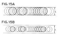
- a power dependency of the recording characteristics was examined.
- P W the power level of the magnetic domain smaller than the land width L as shown by a hatched region in Fig. 15B is formed, good recording characteristics were obtained.
- a duration of a jitter when the random signal has been recorded is equal to 3.0 nsec.
- a C/N ratio when a pattern has repetitively been recorded for a duration of 2 ⁇ is equal to 36 dB.
- a manufacturing step similar to the first embodiment three kinds of magnetic layers 1 to 3 shown in Table 3 were sequentially laminated.
- An alloy layer having a film thickness of 40 nm of tantalum and aluminum was formed, thereby manufacturing a magnetooptic recording medium (magnetooptic disk) which can overwrite by the light modulation.
- Fig. 16 shows a temperature dependency of the magnetic characteristics of each magnetic layer in the magnetooptic recording medium.
- the magnetooptic recording medium satisfies the above medium conditions as will be explained hereinlater.
- the magnetizing state is stable for the bias magnetic field Hb from the beginning.
- the magnetic moment of the iron group element of the magnetic layer 3 is held in the downward direction and the magnetizing state doesn't change. In any of the above cases, therefore, the magnetic layer 3 is oriented into the predetermined magnetizing state.
- the magnetooptic recording medium satisfies the above medium conditions.
- the recording operation has been executed by using the laser power of multivalues.
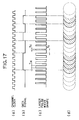
- the recording operation is performed to the magnetooptic disk by modulating a width of laser pulse. That is for a data signal ((b) in Fig. 17) synchronized with a channel clock ((a) in Fig. 17), a laser pulse shown in (c) in Fig. 17 was irradiated to the magnetooptic recording medium. When the data signal is at the high level, the pulse width is equal to ⁇ W . By the irradiation of such a pulse, as shown in (d) in Fig.
- the region corresponding to the whole land width L is heated to a temperature of T2 or higher, so that a recording process occurs.
- the region in the whole land width L is set to a temperature that is equal to or higher than T1 and is less than T2.
- a length of mark which is finally formed by the recording method of the invention is equal to a difference between the length of region in which the magnetic domain is once formed and the length of region in which the magnetic domain is erased just after it was formed, a fluctuation in the mark length is suppressed for a temperature change or a fluctuation in laser power.
- the magnetic layer is once cooled to a temperature of the third temperature T3 or less after the recording mark was formed, when a mark is recorded just after, an influence by the thermal diffusion decreases. A fluctuation of the edge position of the mark that is formed due to the recording pattern decreases. A jitter of an edge signal which is detected is suppressed.
Landscapes
- Physics & Mathematics (AREA)
- Optics & Photonics (AREA)
Applications Claiming Priority (2)
| Application Number | Priority Date | Filing Date | Title |
|---|---|---|---|
| JP279048/92 | 1992-10-16 | ||
| JP4279048A JPH06131722A (ja) | 1992-10-16 | 1992-10-16 | 光磁気記録媒体およびその記録方法 |
Publications (3)
| Publication Number | Publication Date |
|---|---|
| EP0593249A2 true EP0593249A2 (fr) | 1994-04-20 |
| EP0593249A3 EP0593249A3 (fr) | 1994-10-12 |
| EP0593249B1 EP0593249B1 (fr) | 1999-04-28 |
Family
ID=17605676
Family Applications (1)
| Application Number | Title | Priority Date | Filing Date |
|---|---|---|---|
| EP93308100A Expired - Lifetime EP0593249B1 (fr) | 1992-10-16 | 1993-10-12 | Méthode et système d'enregistrement d'information magnéto-optique |
Country Status (4)
| Country | Link |
|---|---|
| US (1) | US5751669A (fr) |
| EP (1) | EP0593249B1 (fr) |
| JP (1) | JPH06131722A (fr) |
| DE (1) | DE69324644T2 (fr) |
Cited By (1)
| Publication number | Priority date | Publication date | Assignee | Title |
|---|---|---|---|---|
| EP0753847A3 (fr) * | 1995-07-10 | 1997-12-29 | Fujitsu Limited | Appareil d'entraínement de disque magnéto-optique permettant une opération de sur-écriture directe et une opération d'écriture après effaçage |
Families Citing this family (8)
| Publication number | Priority date | Publication date | Assignee | Title |
|---|---|---|---|---|
| KR20000022390A (ko) * | 1996-07-12 | 2000-04-25 | 다카노 야스아키 | 광자기기록매체, 그 재생방법 및 재생장치 |
| KR19990023151A (ko) * | 1997-08-27 | 1999-03-25 | 사토 도리 | 광자기기록매체 및 그 재생방법 |
| JP2001319338A (ja) * | 2000-05-11 | 2001-11-16 | Samsung Electronics Co Ltd | 光ディスクの記録装置および記録方法 |
| US6665243B2 (en) * | 2001-04-11 | 2003-12-16 | Zoran Corporation | Method and apparatus for recording a compact disc at a sub-1X speeds |
| ATE324654T1 (de) * | 2002-06-18 | 2006-05-15 | Koninkl Philips Electronics Nv | Verfahren und gerät zur aufzeichnung von markierungen welche daten darstellen in die aufzeichnungsschicht eines optischen datenträgers |
| JP2005025889A (ja) * | 2003-07-04 | 2005-01-27 | Canon Inc | 光学的記録媒体への情報記録方法 |
| JP2006338717A (ja) * | 2005-05-31 | 2006-12-14 | Canon Inc | 光ディスク |
| KR100790902B1 (ko) * | 2007-01-08 | 2008-01-03 | 삼성전자주식회사 | 영상 디스플레이에 사용되는 레이저 다이오드 구동장치 |
Family Cites Families (15)
| Publication number | Priority date | Publication date | Assignee | Title |
|---|---|---|---|---|
| US5239524A (en) * | 1985-06-11 | 1993-08-24 | Nikon Corporation | Over write capable magnetooptical recording method, and magnetooptical recording apparatus and medium used therefor |
| JP2521908B2 (ja) * | 1985-06-11 | 1996-08-07 | 株式会社ニコン | オ―バ―ライト可能な光磁気記録方法、それに使用される光磁気記録装置及び光磁気記録媒体、並びに変調方法、変調装置及び光磁気記録媒体 |
| JPS63249953A (ja) * | 1987-04-03 | 1988-10-17 | Mitsubishi Electric Corp | 光磁気記録再生装置 |
| CA1326547C (fr) * | 1988-07-13 | 1994-01-25 | Masahiko Kaneko | Methode d'enregistrement thermomagnetique |
| JPH0244443A (ja) * | 1988-08-05 | 1990-02-14 | Sanyo Electric Co Ltd | メモリアクセス方式 |
| US5175714A (en) * | 1988-09-30 | 1992-12-29 | Kabushiki Kaisha Toshiba | Method of magneto-optically recording/erasing information and magneto-optical information storage medium including recording and bias layers satisfying certain conditions |
| US5163031A (en) * | 1988-12-07 | 1992-11-10 | Canon Kabushiki Kaisha | Method of recording tetra-value signal on magneto-optical recording medium with plural magnetic layers |
| JP2808640B2 (ja) * | 1989-03-15 | 1998-10-08 | ソニー株式会社 | 光磁気記録方法 |
| JP2707769B2 (ja) * | 1989-11-14 | 1998-02-04 | 三菱電機株式会社 | 光磁気記録媒体及びそれを用いた光磁気記録再生装置 |
| JP2575511B2 (ja) * | 1989-12-08 | 1997-01-29 | インターナショナル・ビジネス・マシーンズ・コーポレーション | 光磁気記録方法及び装置 |
| US5235569A (en) * | 1990-06-13 | 1993-08-10 | Nikon Corporation | Magnetooptical recording method, and apparatus used in the method |
| JP3038853B2 (ja) * | 1990-09-13 | 2000-05-08 | 株式会社ニコン | 高レベルのマージンが拡大したオーバーライト可能な光磁気記録媒体 |
| JPH04134741A (ja) * | 1990-09-27 | 1992-05-08 | Nikon Corp | 4層膜構造のオーバーライト可能な光磁気記録媒体 |
| JP2838908B2 (ja) * | 1990-10-19 | 1998-12-16 | キヤノン株式会社 | 光磁気記録方法 |
| JP2567996B2 (ja) * | 1991-01-23 | 1996-12-25 | インターナショナル・ビジネス・マシーンズ・コーポレイション | 光磁気記録方法及び装置 |
-
1992
- 1992-10-16 JP JP4279048A patent/JPH06131722A/ja active Pending
-
1993
- 1993-10-12 DE DE69324644T patent/DE69324644T2/de not_active Expired - Fee Related
- 1993-10-12 EP EP93308100A patent/EP0593249B1/fr not_active Expired - Lifetime
-
1996
- 1996-06-19 US US08/666,918 patent/US5751669A/en not_active Expired - Fee Related
Cited By (1)
| Publication number | Priority date | Publication date | Assignee | Title |
|---|---|---|---|---|
| EP0753847A3 (fr) * | 1995-07-10 | 1997-12-29 | Fujitsu Limited | Appareil d'entraínement de disque magnéto-optique permettant une opération de sur-écriture directe et une opération d'écriture après effaçage |
Also Published As
| Publication number | Publication date |
|---|---|
| EP0593249A3 (fr) | 1994-10-12 |
| US5751669A (en) | 1998-05-12 |
| JPH06131722A (ja) | 1994-05-13 |
| EP0593249B1 (fr) | 1999-04-28 |
| DE69324644T2 (de) | 1999-10-14 |
| DE69324644D1 (de) | 1999-06-02 |
Similar Documents
| Publication | Publication Date | Title |
|---|---|---|
| US5629909A (en) | Magneto-optical recording medium with initializing layer for initializing different regions in different directions | |
| US5648134A (en) | Thermal recording medium capable of keeping width of mark train constant and recording method for the same | |
| EP0899727B1 (fr) | Méthode de reproduction de signal utilisant le déplacement de paroi de domaine magnétique et appareil pour cela | |
| EP0475446B1 (fr) | Milieu d'enregistrement magnéto-optique susceptible de sur-enregistrement et permettant une marge de l'intensité de rayon de niveau haut élargie | |
| EP0593249A2 (fr) | Méthode d'enregistrement d'information magnéto-optique | |
| US5164926A (en) | Over-write capable magnetooptical recording medium with four magnetic layered structure dispensing with external initializing field | |
| US5323374A (en) | Method of magneto-optical recording | |
| EP0658890A2 (fr) | Milieu d'enregistrement magnéto-optique avec capacités de sur-écriture et méthode pour utiliser celui-ci | |
| EP0513668B1 (fr) | Support d'enregistrement magnéto-optique | |
| US5339298A (en) | Over-write capable magnetooptical recording method with widened power margin, and magnetooptical recording apparatus used in this method | |
| EP0588636A1 (fr) | Milieu d'enregistrement magnéto-optique, capable d'être surécrit | |
| EP0472377B1 (fr) | Méthode et appareil magnéto-optique pour enregistrement/reproduction de données | |
| EP0508376B1 (fr) | Support d'enregistrement magnéto-optique surinscriptible ayant un sillon avec une profondeur dans un intervalle compris entre 30 nm et 80 nm | |
| EP0422783A2 (fr) | Enregistrement magnétooptique | |
| US5587974A (en) | Magneto-optical recording medium having two magnetic layers with perpendicular magnetic anisotropy, and information recording method having the same | |
| US6033538A (en) | Magneto-optical recording medium production method | |
| US5389455A (en) | Over-write capable magnetooptical recording medium having C/N ratio exceeding 53 dB | |
| US20030107956A1 (en) | Magneto-optical recording medium having different magnetic domain radii in recording layer and reproduction layer | |
| JP2828993B2 (ja) | 光磁気記録媒体及びそれを用いた情報記録方法 | |
| KR960016360B1 (ko) | 광자기 기록방법 | |
| EP0470826B1 (fr) | Système d'enregistrement magnéto-optique | |
| JP3592399B2 (ja) | 光磁気記録媒体 | |
| JP3328989B2 (ja) | 光磁気記録媒体 | |
| JPH04281239A (ja) | 光磁気記録媒体 | |
| EP0780841A2 (fr) | Milieu d'enregistrement magnéto-optique utilisant un matériau magnétique à transformation de phase et méthode d'enregistrement utilisant le milieu |
Legal Events
| Date | Code | Title | Description |
|---|---|---|---|
| PUAI | Public reference made under article 153(3) epc to a published international application that has entered the european phase |
Free format text: ORIGINAL CODE: 0009012 |
|
| AK | Designated contracting states |
Kind code of ref document: A2 Designated state(s): BE CH DE ES FR GB IT LI NL SE |
|
| PUAL | Search report despatched |
Free format text: ORIGINAL CODE: 0009013 |
|
| AK | Designated contracting states |
Kind code of ref document: A3 Designated state(s): BE CH DE ES FR GB IT LI NL SE |
|
| 17P | Request for examination filed |
Effective date: 19950224 |
|
| 17Q | First examination report despatched |
Effective date: 19961227 |
|
| GRAG | Despatch of communication of intention to grant |
Free format text: ORIGINAL CODE: EPIDOS AGRA |
|
| GRAG | Despatch of communication of intention to grant |
Free format text: ORIGINAL CODE: EPIDOS AGRA |
|
| GRAG | Despatch of communication of intention to grant |
Free format text: ORIGINAL CODE: EPIDOS AGRA |
|
| GRAH | Despatch of communication of intention to grant a patent |
Free format text: ORIGINAL CODE: EPIDOS IGRA |
|
| GRAH | Despatch of communication of intention to grant a patent |
Free format text: ORIGINAL CODE: EPIDOS IGRA |
|
| GRAA | (expected) grant |
Free format text: ORIGINAL CODE: 0009210 |
|
| AK | Designated contracting states |
Kind code of ref document: B1 Designated state(s): BE CH DE ES FR GB IT LI NL SE |
|
| PG25 | Lapsed in a contracting state [announced via postgrant information from national office to epo] |
Ref country code: SE Free format text: THE PATENT HAS BEEN ANNULLED BY A DECISION OF A NATIONAL AUTHORITY Effective date: 19990428 Ref country code: LI Free format text: LAPSE BECAUSE OF FAILURE TO SUBMIT A TRANSLATION OF THE DESCRIPTION OR TO PAY THE FEE WITHIN THE PRESCRIBED TIME-LIMIT Effective date: 19990428 Ref country code: ES Free format text: THE PATENT HAS BEEN ANNULLED BY A DECISION OF A NATIONAL AUTHORITY Effective date: 19990428 Ref country code: CH Free format text: LAPSE BECAUSE OF FAILURE TO SUBMIT A TRANSLATION OF THE DESCRIPTION OR TO PAY THE FEE WITHIN THE PRESCRIBED TIME-LIMIT Effective date: 19990428 Ref country code: BE Free format text: LAPSE BECAUSE OF FAILURE TO SUBMIT A TRANSLATION OF THE DESCRIPTION OR TO PAY THE FEE WITHIN THE PRESCRIBED TIME-LIMIT Effective date: 19990428 |
|
| REG | Reference to a national code |
Ref country code: CH Ref legal event code: EP |
|
| REF | Corresponds to: |
Ref document number: 69324644 Country of ref document: DE Date of ref document: 19990602 |
|
| ET | Fr: translation filed | ||
| REG | Reference to a national code |
Ref country code: CH Ref legal event code: PL |
|
| PLBE | No opposition filed within time limit |
Free format text: ORIGINAL CODE: 0009261 |
|
| 26N | No opposition filed | ||
| REG | Reference to a national code |
Ref country code: GB Ref legal event code: IF02 |
|
| PGFP | Annual fee paid to national office [announced via postgrant information from national office to epo] |
Ref country code: GB Payment date: 20040928 Year of fee payment: 12 |
|
| PGFP | Annual fee paid to national office [announced via postgrant information from national office to epo] |
Ref country code: NL Payment date: 20041018 Year of fee payment: 12 |
|
| PGFP | Annual fee paid to national office [announced via postgrant information from national office to epo] |
Ref country code: FR Payment date: 20041022 Year of fee payment: 12 |
|
| PGFP | Annual fee paid to national office [announced via postgrant information from national office to epo] |
Ref country code: DE Payment date: 20041216 Year of fee payment: 12 |
|
| PG25 | Lapsed in a contracting state [announced via postgrant information from national office to epo] |
Ref country code: IT Free format text: LAPSE BECAUSE OF NON-PAYMENT OF DUE FEES Effective date: 20051012 Ref country code: GB Free format text: LAPSE BECAUSE OF NON-PAYMENT OF DUE FEES Effective date: 20051012 |
|
| PG25 | Lapsed in a contracting state [announced via postgrant information from national office to epo] |
Ref country code: NL Free format text: LAPSE BECAUSE OF NON-PAYMENT OF DUE FEES Effective date: 20060501 |
|
| PG25 | Lapsed in a contracting state [announced via postgrant information from national office to epo] |
Ref country code: DE Free format text: LAPSE BECAUSE OF NON-PAYMENT OF DUE FEES Effective date: 20060503 |
|
| GBPC | Gb: european patent ceased through non-payment of renewal fee |
Effective date: 20051012 |
|
| PG25 | Lapsed in a contracting state [announced via postgrant information from national office to epo] |
Ref country code: FR Free format text: LAPSE BECAUSE OF NON-PAYMENT OF DUE FEES Effective date: 20060630 |
|
| NLV4 | Nl: lapsed or anulled due to non-payment of the annual fee |
Effective date: 20060501 |
|
| REG | Reference to a national code |
Ref country code: FR Ref legal event code: ST Effective date: 20060630 |