EP0470830B1 - Anneau torique, métallique et creux et son procédé pour produire la même chose - Google Patents
Anneau torique, métallique et creux et son procédé pour produire la même chose Download PDFInfo
- Publication number
- EP0470830B1 EP0470830B1 EP91307263A EP91307263A EP0470830B1 EP 0470830 B1 EP0470830 B1 EP 0470830B1 EP 91307263 A EP91307263 A EP 91307263A EP 91307263 A EP91307263 A EP 91307263A EP 0470830 B1 EP0470830 B1 EP 0470830B1
- Authority
- EP
- European Patent Office
- Prior art keywords
- ring
- metallic
- hollow
- circumferential direction
- metallic shell
- Prior art date
- Legal status (The legal status is an assumption and is not a legal conclusion. Google has not performed a legal analysis and makes no representation as to the accuracy of the status listed.)
- Expired - Lifetime
Links
Images

Classifications
-
- F—MECHANICAL ENGINEERING; LIGHTING; HEATING; WEAPONS; BLASTING
- F16—ENGINEERING ELEMENTS AND UNITS; GENERAL MEASURES FOR PRODUCING AND MAINTAINING EFFECTIVE FUNCTIONING OF MACHINES OR INSTALLATIONS; THERMAL INSULATION IN GENERAL
- F16J—PISTONS; CYLINDERS; SEALINGS
- F16J15/00—Sealings
- F16J15/02—Sealings between relatively-stationary surfaces
- F16J15/06—Sealings between relatively-stationary surfaces with solid packing compressed between sealing surfaces
- F16J15/08—Sealings between relatively-stationary surfaces with solid packing compressed between sealing surfaces with exclusively metal packing
- F16J15/0887—Sealings between relatively-stationary surfaces with solid packing compressed between sealing surfaces with exclusively metal packing the sealing effect being obtained by elastic deformation of the packing
- F16J15/0893—Sealings between relatively-stationary surfaces with solid packing compressed between sealing surfaces with exclusively metal packing the sealing effect being obtained by elastic deformation of the packing the packing having a hollow profile
-
- B—PERFORMING OPERATIONS; TRANSPORTING
- B21—MECHANICAL METAL-WORKING WITHOUT ESSENTIALLY REMOVING MATERIAL; PUNCHING METAL
- B21D—WORKING OR PROCESSING OF SHEET METAL OR METAL TUBES, RODS OR PROFILES WITHOUT ESSENTIALLY REMOVING MATERIAL; PUNCHING METAL
- B21D53/00—Making other particular articles
- B21D53/16—Making other particular articles rings, e.g. barrel hoops
- B21D53/18—Making other particular articles rings, e.g. barrel hoops of hollow or C-shaped cross-section, e.g. for curtains, for eyelets
Definitions
- This invention relates to welded metallic hollow O-rings for use in wide applications, for example, pipe fittings of ultra-high vacuum apparatus, apparatus for nuclear power stations, or pressure sensors of safety valves incorporated into a high temperature-high pressure part of a fuel injector for a diesel engine.
- the invention also relates to a process for producing the same.
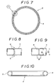
- a known welded metallic hollow O-ring is, for example, described in Aerospace Material Specification AMS7325C published by the Society of Automotive Engines Inc. of New York, USA in 1966. Such a metallic hollow O-ring is shown in the accompanying Fig. 7.
- This metallic hollow O-ring 2 may be produced by bending appropriately a metallic hollow tube 4 into a ring form, and welding both ends of said tube 4 together at a point of X as shown in Fig. 7.
- weld beads are formed at the welded joint, which project respectively inward and outward on the inner and outer peripheries of the metallic hollow tube 4.
- the bead 6 formed on the outer periphery of said tube 4 must be removed therefrom and the surface of said tube 4 from which the bead 6 has been removed must be abraded (polished) to attain a smooth surface.
- the conventional O-ring having a weld bead projecting outwardly on its outer periphery of tube is used as it is, there is a possibility that the O-ring will deteriorate in its sealing performance, because the weld bead intervenes between the O-ring and a member, with which said O-ring is to be into contact, thereby forming a space between said O-ring and said member.
- the conventional metallic hollow O-ring 2 illustrated above when the weld bead projecting outwardly is abraded at the welded joint, the outside diameter of the metallic hollow tube 4 after the abrading thereof in the region of W as shown in Fig. 9 becomes d1 relative to the original outside diameter d0 of said tube 4, and from this it follows that the outside diameter of the tube 4 in the region of W is shortened by a difference between d0 and d1.
- the conventional metallic hollow O-ring 2 when used, will deteriorate in sealing performance or mechanical strength according to the degree of accuracy in abrading the weld bead surface or the state of the weld bead 6 projecting inside the metallic hollow tube 4.
- unwelded metallic hollow O-rings 8 having a C-shaped cross section and an opening 9 circumferentially formed on the outer peripheral surface of O-ring 8 are also known. Examples are shown in Catalogue No. 35 of Mitsubishi Cable Industries, Ltd entitled “Metal C-Rings” and dated August 1982. Such O-rings are weak in strength in comparison with the welded metallic hollow O-rings and, moreover, a clamping pressure to be applied thereto cannot be increased so high. In addition the surface of a flange, with which the above-mentioned unwelded metallic hollow O-ring is in contact, is required to have good accuracy. Thus the conditions under which said metallic hollow O-ring is used are limited in comparison with the conditions in the case of the welded metallic hollow O-ring.
- the present invention has been made in view of such circumstances as mentioned above, and an object of the invention is to provide welded metallic hollow O-rings which are easily produced, capable of mass production and excellent in sealing properties as well as in mechanical strength.
- Another object of the invention is to provide a process for producing metallic hollow O-rings, by which such welded metallic hollow O-rings as described above can be obtained at low price and good productivity rate.
- a metallic hollow O-ring comprising a metallic shell formed continuously in the circumferential direction into a ring form and having a continuous hollow portion formed in the circumferential direction inside the metallic shell, said metallic shell having only one pair of edge portions extending substantially circumferentially and adjacent to each other.
- the present invention is characterised in that said edge portions are welded intermittently or continuously in the circumferential direction.
- a process for producing a metallic hollow O-ring comprising a step of bending a piece of metal to form a ring-like metallic shell so that a hollow portion is formed continuously in the circumferential direction inside the metallic shell and, at the same time, an opening defined between the edge portions of said metallic shell is formed continuously in the circumferential direction, said metallic shell having only one pair of edge portions extending substantially circumferentially and adjacent to each other.
- the present invention is characterised by the step of welding said portions together intermittently or continuously in the circumferential direction so that said opening is blocked partially or wholly.
- the desired O-ring is not produced by welding together the end portions of a metallic tube, but is produced by welding the edge portions of a metallic shell together in the circumferential direction.
- Providing the welded portion of said metallic shell does not come in contact with a member to which the O-ring is applied, there is no need for removal of weld beads formed at the welded joint. Accordingly, it becomes possible to prevent the metallic O-ring from the problems caused by removal of the weld bead such as a decrease in mechanical strength and deterioration in sealing properties by reducing the outside diameter of the O-ring.
- the metallic hollow O-rings of the present invention are free from such inconveniences as associated with the conventional unwelded metallic hollow O-rings having a C-shaped cross-section.
- the metallic hollow O-rings of the invention preferably have an outside diameter of 6 to 100 mm, more preferably 12 to 25 mm.
- a preferred process for producing a metallic hollow O-ring is characterized by cutting a cylindrical metallic tube to an appropriate length, and folding back (preferably outwardly) the edges of the cut tube so that a continuous hollow portion is formed in the circumferential direction inside the fold.
- the metallic hollow O-ring is produced by pressing a small diameter tube in such a manner, whereby dimensional stability and mass production can be assured.
- the metallic hollow O-ring 10 of the invention shown in Fig. 1 is composed of a metallic shell 12 which continues in the circumferential direction so as to have a ring-like form, and forms therein continuously a hollow portion 14 of a circular cross section in the circumferential direction.
- the metallic hollow O-ring 10 has an outside diameter of 6 to 100 mm, preferably 12 to 25 mm.
- This metallic shell 12 is designed to have on its outer peripheral portion a pair of butt edges which are formed continuously in the circumferential direction so as to be opposite to each other and are to be butt welded in the manner as will be mentioned later. Because the sealing surface (the surface of the metallic hollow O-ring 10 at which said O-ring will come in contact with a member to which the O-ring is applied) of the metallic hollow O-ring 10 includes the upper surface 18 and lower surface 20, even when the welded joint is present on the outer peripheral portion of the O-ring 10, the weld bead formed on said welded joint will not exert adverse effect on the sealing performance of said O-ring 10. It is not necessary to carry out butt welding all over the butt edge portions 16, and this may be carried out intermittently.
- the hollow portion 14 is not tight sealed, but it becomes possible to adjust the balance between inside and outside the metallic shell 12 by introducing a pressure fluid into the hollow portion 14.
- the hollow portion 14 When the hollow portion 14 is tight sealed, it may be designed that a pressure fluid is encapsulated into said hollow portion 14.
- the metallic shell 12 may be made of not only a single-layer metal plate but also a laminated metal plate.
- a spring steel which could not be used in the conventional welded metallic hollow O-rings because the welded joint decreases in strength by heat deterioration.
- the reason therefor is that in the metallic hollow O-rings of the present invention, the welded joint 16 will not be included in the sealing surface of said O-rings.
- the metallic shell 12 is formed from the spring steel, the resulting metallic hollow O-ring further increases in elasticity. Further, the surface of this metallic shell may be subjected to surface treatment such as plating in order to improve the suitability of the resulting metallic hollow O-ring for a member of which said O-ring is applied.
- Such metallic hollow O-ring 10 as mentioned above may be produced by the process as will be illustrated hereinafter.
- a disk material 22 for the metallic shell as shown in Fig. 2(A) is used, and the disk material 22 is first pressed by means of a mold or the like in the manner as shown in Fig. 2(B) so that a disk-like bottom portion 24 is formed. Then, the material 22 is cut along a cut-through line 26 to obtain a ring having an L-shaped cross-section as shown in Fig. 2(C). This ring is bent by means of a mold or the like in the manner as shown in Fig. 2(D) and (E) so that the ring comes to have a circular cross-section, whereby the edge portions 28 of the material 22 approach at the outer peripheral portion of the ring, and an opening 30 is formed between the edge portions 28. Thereafter, the edge portions 28 are butt welded so as to block the opening 30 formed continuously in the circumferential direction, whereby the metallic hollow O-ring 10 as shown in Fig. 1 is obtained.
- the means for welding the above-mentioned edge portions 28 is not particularly limited to specific ones, and useful means include TIG welding, laser welding, seam welding, spot welding, etc., the welding operation of which is desirably automated.
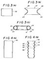
- a small diameter cylindrical metallic tube shown in Fig. 3(A) is used as a material 32 for the metallic shell, the material 32 is cut off in an appropriate length, and the ends of the cut tube (the edge portions 28) are folded outwardly in the manner as shown in Fig. 3(B). And then, by means of a plurality of bending operations, a ring having a hollow portion 14 of a circular cross-section as shown in Fig. 3(C) is finally obtained.
- the edge portions 28 are butt welded so that an opening 30 of the hollow portion 14 formed continuously in the circumferential direction is blocked, whereby such a metallic hollow O-ring 10 as shown in Fig. 1 is obtained.
- the metallic hollow O-ring is produced by pressing a small diameter tube in the manner described, hence dimensional stability and mass production can be assured thereby.
- a relatively long metallic tube 40 is used.
- the metallic tube 40 is formed by means of the liquid pressure molding or the like into a bellows-like form, and each wavy portion thus formed is cut off from the tube in the axial direction along cut-through lines 44 to obtain materials 42 and 46 for the metallic shell.
- the material 42 for the metallic shell is concavo-convex, and can be formed by the bending steps as shown in Fig. 3(B) and (c) into such a metallic hollow O-ring as shown in Fig. 1.
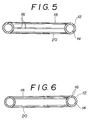
- the material 46 is convexo-concave, and can be formed into such a metallic hollow O-ring as shown in Fig. 6 by the bending step as mentioned above but reversing the bending direction and carrying out the welding at the inside diameter side.
- welded joint 16 may be formed at the inner peripheral portion of the O-ring.
- the sealing surface of the O-ring is the outer peripheral or inner peripheral portion of said O-ring, as shown in Fig. 6, the welded joint 16 may be formed on the upper surface 18 or lower surface 20 of said O-ring.
- the metallic hollow O-rings of the invention may be shaped into not only a circular form but also into varied forms such as an elliptical form, square form and the like.
- said O-rings are not produced by welding both ends of a metallic tube together, but are produced by welding the metallic tube in the circumferential direction at a portion of said tube where the resulting O-ring does not come in contact with a member to which said O-ring is applied, hence there is no need of removing a weld bead formed at the welded joint of the O-ring. Accordingly, it becomes possible to prevent the metallic hollow O-ring from decreasing in mechanical strength caused by the removal of the weld bead or deteriorating in sealing properties by reduction in diameter of said O-ring.
- the process for producing the metallic hollow O-rings of the present invention is easy to automate, whereby the mass production of the desired O-ring is made possible and also the cost of production is reduced. Further, because precision of the welded joint required in the O-rings of the present invention is not so high, the number of rejected products found is small and in this respect the productivity will also be improved.
- the metallic hollow O-rings of the present invention are free from such inconveniences as associated with the conventional unwelded metallic hollow O-rings having a C-shaped cross-section.
- the metallic hollow O-ring of the present invention is less in leakage of helium gas and excellent in gas tight properties in comparison with the metallic C-ring of the comparative example.
Landscapes
- Engineering & Computer Science (AREA)
- General Engineering & Computer Science (AREA)
- Mechanical Engineering (AREA)
- Gasket Seals (AREA)
- Inorganic Compounds Of Heavy Metals (AREA)
Claims (6)
- Joint torique métallique creux (10) comprenant une enveloppe métallique (12) formée de façon continue en direction circonférentielle avec la forme d'un anneau et ayant une partie creuse continue (14) formée en direction circonférentielle à l'intérieur de l'enveloppe métallique (12), l'enveloppe métallique n'ayant que deux parties de bord (16) disposées en direction pratiquement circonférentielle et adjacentes l'une à l'autre, caractérisé en ce que les parties de bord (16) sont soudées de façon intermittente ou continue dans la direction circonférentielle.
- Joint torique métallique creux (10) selon la revendication 1, dans lequel le diamètre externe du joint torique (10) ne dépasse pas 100 mm.
- Procédé de fabrication d'un joint torique métallique creux (10), comprenant une étape de pliage d'une pièce métallique pour la formation d'une enveloppe métallique (12) en forme d'anneau de manière qu'une partie creuse (14) soit réalisée de façon continue en direction circonférentielle à l'intérieur de l'enveloppe métallique et simultanément une ouverture délimitée entre les parties de bord (16) de l'enveloppe métallique est formée de façon continue en direction circonférentielle, l'enveloppe métallique ayant une seule paire de parties de bord (16) disposées en direction pratiquement circonférentielle et adjacentes mutuellement, caractérisé par l'étape de soudage des parties de bord (16) l'une à l'autre par intermittence ou de façon continue dans la direction circonférentielle afin que l'ouverture soit bouchée partiellement ou totalement.
- Procédé de fabrication d'un joint torique métallique creux (10) selon la revendication 3, dans lequel le diamètre externe du joint torique (10) ne dépasse pas 100 mm.
- Procédé de fabrication d'un joint torique métallique creux (10) selon la revendication 3 ou 4, dans lequel le matériau initial est sous forme d'un tube métallique cylindrique (32) découpé à une longueur convenable, et dans lequel les parties de bord (28) du tube métallique coupé sont pliées vers l'extérieur afin qu'une partie creuse soit formée dans le tube métallique coupé de façon continue dans la direction circonférentielle.
- Procédé de fabrication d'un joint torique métallique creux (10) selon la revendication 3 ou 4, dans lequel le matériau initial est une plaque circulaire plate (22), et l'enveloppe métallique en forme d'anneau est réalisée par emboutissage vers le haut d'un tronçon circulaire interne de la plaque (24), par découpe de la partie circulaire supérieure résultante pour la formation d'un anneau ayant une section transversale en L, et par pliage des bords supérieurs internes et inférieurs externes (28) l'un vers l'autre afin qu'une partie creuse (14) soit formée à l'intérieur de façon continue dans la direction circonférentielle.
Applications Claiming Priority (2)
| Application Number | Priority Date | Filing Date | Title |
|---|---|---|---|
| JP208779/90 | 1990-08-07 | ||
| JP20877990 | 1990-08-07 |
Publications (2)
| Publication Number | Publication Date |
|---|---|
| EP0470830A1 EP0470830A1 (fr) | 1992-02-12 |
| EP0470830B1 true EP0470830B1 (fr) | 1995-04-19 |
Family
ID=16561961
Family Applications (1)
| Application Number | Title | Priority Date | Filing Date |
|---|---|---|---|
| EP91307263A Expired - Lifetime EP0470830B1 (fr) | 1990-08-07 | 1991-08-07 | Anneau torique, métallique et creux et son procédé pour produire la même chose |
Country Status (4)
| Country | Link |
|---|---|
| EP (1) | EP0470830B1 (fr) |
| AT (1) | ATE121519T1 (fr) |
| CA (1) | CA2048586A1 (fr) |
| DE (1) | DE69109020T2 (fr) |
Families Citing this family (12)
| Publication number | Priority date | Publication date | Assignee | Title |
|---|---|---|---|---|
| FR2866394B1 (fr) * | 2004-02-12 | 2006-05-19 | Attax | Jonc de renfort notamment pour un conduit de systeme d'alimentation en air d'un moteur de vehicule automobile |
| US20090056223A1 (en) * | 2007-09-04 | 2009-03-05 | Patel Sunilkant A | Quench ring rim and methods for fabricating |
| DE102008035186A1 (de) | 2008-07-28 | 2010-02-04 | Elringklinger Ag | Verfahren zum Herstellen eines Formdichtringes |
| DE102009022393B4 (de) * | 2009-05-22 | 2011-09-22 | Federal-Mogul Sealing Systems Gmbh | Verfahren zur Herstellung metallischer Elemente, insbesondere Dichtelemente |
| DE102009022392B4 (de) * | 2009-05-22 | 2011-09-22 | Federal-Mogul Sealing Systems Gmbh | Verfahren zur Herstellung von metallischen Stopperelementen für Flachdichtungen |
| WO2011113954A1 (fr) * | 2010-03-19 | 2011-09-22 | Otto Bihler Maschinenfabrik Gmbh & Co. Kg | Procédé et dispositif de fabrication de bagues profilées |
| JP5714966B2 (ja) * | 2011-04-11 | 2015-05-07 | ニチアス株式会社 | 渦巻形ガスケット |
| WO2013151358A1 (fr) * | 2012-04-04 | 2013-10-10 | 한국기초과학지원연구원 | Joint torique métallique à haute élasticité |
| DE202013009887U1 (de) | 2013-11-29 | 2014-12-01 | Reinz-Dichtungs-Gmbh | Metallische Flachdichtung |
| CN104708181A (zh) * | 2013-12-17 | 2015-06-17 | 北京有色金属研究总院 | 一种铝合金空心圆环件的焊接方法 |
| DE102015220127A1 (de) | 2015-10-15 | 2017-04-20 | Wacker Chemie Ag | Vorrichtung zur Isolierung und Abdichtung von Elektrodenhalterungen in CVD Reaktoren |
| CN113020904A (zh) * | 2021-02-26 | 2021-06-25 | 临沂大学 | C型内开口薄壁金属环形件制作方法和设备 |
Family Cites Families (7)
| Publication number | Priority date | Publication date | Assignee | Title |
|---|---|---|---|---|
| US3919761A (en) * | 1972-10-31 | 1975-11-18 | Rmi Co | Method of handling corrosive substances |
| NO136223C (no) * | 1973-02-27 | 1977-08-03 | Sentralinstituttet For Ind For | Fremgangsm}te til } skaffe en fast og fortrinnsvis tett forbindelse mellom et hovedsakelig sylindrisk indre legeme og et hovedsakelig sylindrisk ytre legeme som omgir det indre, og middel til utf¦relse av fremgangsm}ten. |
| DE2364223C3 (de) * | 1973-12-22 | 1978-04-27 | Skf Kugellagerfabriken Gmbh, 8720 Schweinfurt | Verfahren zur Herstellung konzentrischer Maschinenelemente |
| DE2528905C3 (de) * | 1975-06-28 | 1979-08-02 | Audi Nsu Auto Union Ag, 7107 Neckarsulm | Verfahren zur Herstellung von metallischen Ringen |
| US4226449A (en) * | 1979-05-29 | 1980-10-07 | American Machine & Hydraulics | Pipe clamp |
| EP0204145A1 (fr) * | 1985-05-10 | 1986-12-10 | Siemens Aktiengesellschaft | Pièce pour le raccordement par soudure de tuyaux |
| AU3858789A (en) * | 1988-06-16 | 1990-01-12 | Tri-Tech Systems International Inc. | O-ring seals, article of manufacture incorporating the same and methods of making and using the same |
-
1991
- 1991-08-07 AT AT91307263T patent/ATE121519T1/de not_active IP Right Cessation
- 1991-08-07 EP EP91307263A patent/EP0470830B1/fr not_active Expired - Lifetime
- 1991-08-07 DE DE69109020T patent/DE69109020T2/de not_active Expired - Fee Related
- 1991-08-07 CA CA002048586A patent/CA2048586A1/fr not_active Abandoned
Also Published As
| Publication number | Publication date |
|---|---|
| CA2048586A1 (fr) | 1992-02-08 |
| DE69109020D1 (de) | 1995-05-24 |
| EP0470830A1 (fr) | 1992-02-12 |
| DE69109020T2 (de) | 1995-08-31 |
| ATE121519T1 (de) | 1995-05-15 |
Similar Documents
| Publication | Publication Date | Title |
|---|---|---|
| EP0470830B1 (fr) | Anneau torique, métallique et creux et son procédé pour produire la même chose | |
| US4361335A (en) | Annular gasket for static sealing for very high temperatures and small pressure drops, and method of making | |
| US4185858A (en) | Secondary seal for tubing joined via V-band couplings | |
| US5415443A (en) | Pipe with flange for pipe fitting, pipe flange used therewith and method of joining said pipe with flange with pipe | |
| US5226683A (en) | Reusable metallic seal using memory metal | |
| JP4556205B2 (ja) | 金属ガスケット | |
| GB2382851A (en) | Annular metallic seal | |
| JPS61147987A (ja) | 縦の継ぎ目を溶接した廃ガス装置用管状部品の製造法 | |
| US4112568A (en) | Method of fabricating a flow device | |
| US4282643A (en) | Method of making metal gaskets | |
| JPH04331876A (ja) | ジャケットガスケット | |
| JPH06300136A (ja) | 金属中空oリング及びその製造方法 | |
| US3850796A (en) | Leakproof connection means between hoop and nozzle of pressure vessel | |
| JPH09264427A (ja) | メタルガスケット | |
| JP2007010100A (ja) | アウターリング及び真空装置用クランプ形継手 | |
| US4311505A (en) | Method of manufacturing glass-lined metal tubes | |
| US3352006A (en) | Method of making hollow ring gaskets | |
| US8621733B2 (en) | Device for preparing the end faces of thin-walled jackets for welding | |
| JP2003156147A (ja) | メタルガスケット | |
| JP2001153229A (ja) | 中空金属oリング | |
| JP4389241B2 (ja) | 金属リングガスケット | |
| JP3590777B2 (ja) | 渦巻形ガスケット | |
| US3691614A (en) | Method of producing a sealing-tight joint between two tubes on different materials | |
| JP2015031358A (ja) | メタルcリング及びその製造方法 | |
| JPH1130333A (ja) | メタルcリング |
Legal Events
| Date | Code | Title | Description |
|---|---|---|---|
| PUAI | Public reference made under article 153(3) epc to a published international application that has entered the european phase |
Free format text: ORIGINAL CODE: 0009012 |
|
| AK | Designated contracting states |
Kind code of ref document: A1 Designated state(s): AT BE CH DE DK ES FR GB GR IT LI LU NL SE |
|
| 17P | Request for examination filed |
Effective date: 19920728 |
|
| 17Q | First examination report despatched |
Effective date: 19931112 |
|
| GRAA | (expected) grant |
Free format text: ORIGINAL CODE: 0009210 |
|
| AK | Designated contracting states |
Kind code of ref document: B1 Designated state(s): AT BE CH DE DK ES FR GB GR IT LI LU NL SE |
|
| PG25 | Lapsed in a contracting state [announced via postgrant information from national office to epo] |
Ref country code: NL Free format text: LAPSE BECAUSE OF NON-PAYMENT OF DUE FEES Effective date: 19950419 Ref country code: LI Effective date: 19950419 Ref country code: GR Free format text: LAPSE BECAUSE OF FAILURE TO SUBMIT A TRANSLATION OF THE DESCRIPTION OR TO PAY THE FEE WITHIN THE PRESCRIBED TIME-LIMIT Effective date: 19950419 Ref country code: ES Free format text: THE PATENT HAS BEEN ANNULLED BY A DECISION OF A NATIONAL AUTHORITY Effective date: 19950419 Ref country code: DK Effective date: 19950419 Ref country code: CH Effective date: 19950419 Ref country code: BE Effective date: 19950419 Ref country code: AT Effective date: 19950419 |
|
| REF | Corresponds to: |
Ref document number: 121519 Country of ref document: AT Date of ref document: 19950515 Kind code of ref document: T |
|
| REF | Corresponds to: |
Ref document number: 69109020 Country of ref document: DE Date of ref document: 19950524 |
|
| ITF | It: translation for a ep patent filed | ||
| PG25 | Lapsed in a contracting state [announced via postgrant information from national office to epo] |
Ref country code: SE Effective date: 19950719 |
|
| REG | Reference to a national code |
Ref country code: CH Ref legal event code: PL |
|
| ET | Fr: translation filed | ||
| PG25 | Lapsed in a contracting state [announced via postgrant information from national office to epo] |
Ref country code: LU Free format text: LAPSE BECAUSE OF NON-PAYMENT OF DUE FEES Effective date: 19950831 |
|
| NLV1 | Nl: lapsed or annulled due to failure to fulfill the requirements of art. 29p and 29m of the patents act | ||
| PLBE | No opposition filed within time limit |
Free format text: ORIGINAL CODE: 0009261 |
|
| STAA | Information on the status of an ep patent application or granted ep patent |
Free format text: STATUS: NO OPPOSITION FILED WITHIN TIME LIMIT |
|
| 26N | No opposition filed | ||
| PGFP | Annual fee paid to national office [announced via postgrant information from national office to epo] |
Ref country code: GB Payment date: 19990804 Year of fee payment: 9 |
|
| PGFP | Annual fee paid to national office [announced via postgrant information from national office to epo] |
Ref country code: DE Payment date: 19990809 Year of fee payment: 9 |
|
| PGFP | Annual fee paid to national office [announced via postgrant information from national office to epo] |
Ref country code: FR Payment date: 19990810 Year of fee payment: 9 |
|
| PG25 | Lapsed in a contracting state [announced via postgrant information from national office to epo] |
Ref country code: GB Free format text: LAPSE BECAUSE OF NON-PAYMENT OF DUE FEES Effective date: 20000807 |
|
| GBPC | Gb: european patent ceased through non-payment of renewal fee |
Effective date: 20000807 |
|
| PG25 | Lapsed in a contracting state [announced via postgrant information from national office to epo] |
Ref country code: FR Free format text: LAPSE BECAUSE OF NON-PAYMENT OF DUE FEES Effective date: 20010430 |
|
| PG25 | Lapsed in a contracting state [announced via postgrant information from national office to epo] |
Ref country code: DE Free format text: LAPSE BECAUSE OF NON-PAYMENT OF DUE FEES Effective date: 20010501 |
|
| REG | Reference to a national code |
Ref country code: FR Ref legal event code: ST |
|
| PG25 | Lapsed in a contracting state [announced via postgrant information from national office to epo] |
Ref country code: IT Free format text: LAPSE BECAUSE OF NON-PAYMENT OF DUE FEES Effective date: 20050807 |