EP0470844A2 - Verdrahtungsanordnung mit ringförmigem Stab vom Typ Bus - Google Patents
Verdrahtungsanordnung mit ringförmigem Stab vom Typ Bus Download PDFInfo
- Publication number
- EP0470844A2 EP0470844A2 EP91307296A EP91307296A EP0470844A2 EP 0470844 A2 EP0470844 A2 EP 0470844A2 EP 91307296 A EP91307296 A EP 91307296A EP 91307296 A EP91307296 A EP 91307296A EP 0470844 A2 EP0470844 A2 EP 0470844A2
- Authority
- EP
- European Patent Office
- Prior art keywords
- rings
- circuit
- ring
- tubing
- joint
- Prior art date
- Legal status (The legal status is an assumption and is not a legal conclusion. Google has not performed a legal analysis and makes no representation as to the accuracy of the status listed.)
- Withdrawn
Links
- RYGMFSIKBFXOCR-UHFFFAOYSA-N Copper Chemical compound [Cu] RYGMFSIKBFXOCR-UHFFFAOYSA-N 0.000 claims abstract description 30
- 229910052802 copper Inorganic materials 0.000 claims abstract description 30
- 239000010949 copper Substances 0.000 claims abstract description 30
- 238000000034 method Methods 0.000 claims abstract description 10
- 239000012809 cooling fluid Substances 0.000 claims abstract description 6
- XLYOFNOQVPJJNP-UHFFFAOYSA-N water Substances O XLYOFNOQVPJJNP-UHFFFAOYSA-N 0.000 claims description 15
- 238000004804 winding Methods 0.000 claims description 10
- 238000005219 brazing Methods 0.000 claims description 7
- 239000000463 material Substances 0.000 claims 2
- 238000004519 manufacturing process Methods 0.000 claims 1
- 238000005476 soldering Methods 0.000 claims 1
- 238000009413 insulation Methods 0.000 abstract description 21
- 238000001816 cooling Methods 0.000 description 17
- 239000007788 liquid Substances 0.000 description 9
- 239000002826 coolant Substances 0.000 description 8
- 230000008901 benefit Effects 0.000 description 7
- 238000013459 approach Methods 0.000 description 6
- 230000000712 assembly Effects 0.000 description 6
- 238000000429 assembly Methods 0.000 description 6
- 239000004020 conductor Substances 0.000 description 6
- 238000013461 design Methods 0.000 description 5
- 238000010292 electrical insulation Methods 0.000 description 3
- 230000002093 peripheral effect Effects 0.000 description 3
- 229910001220 stainless steel Inorganic materials 0.000 description 3
- 239000010935 stainless steel Substances 0.000 description 3
- 229910000831 Steel Inorganic materials 0.000 description 2
- 239000011162 core material Substances 0.000 description 2
- 238000012552 review Methods 0.000 description 2
- 239000007787 solid Substances 0.000 description 2
- 239000010959 steel Substances 0.000 description 2
- 238000012546 transfer Methods 0.000 description 2
- 230000009286 beneficial effect Effects 0.000 description 1
- 230000015572 biosynthetic process Effects 0.000 description 1
- 238000010276 construction Methods 0.000 description 1
- 239000000356 contaminant Substances 0.000 description 1
- 239000000110 cooling liquid Substances 0.000 description 1
- 239000000498 cooling water Substances 0.000 description 1
- 238000010438 heat treatment Methods 0.000 description 1
- 230000006698 induction Effects 0.000 description 1
- 238000005304 joining Methods 0.000 description 1
- 238000003475 lamination Methods 0.000 description 1
- 238000003754 machining Methods 0.000 description 1
- 230000007246 mechanism Effects 0.000 description 1
- 238000012986 modification Methods 0.000 description 1
- 230000004048 modification Effects 0.000 description 1
- 230000002265 prevention Effects 0.000 description 1
- 229910000679 solder Inorganic materials 0.000 description 1
- 230000009466 transformation Effects 0.000 description 1
Images


Classifications
-
- H—ELECTRICITY
- H02—GENERATION; CONVERSION OR DISTRIBUTION OF ELECTRIC POWER
- H02K—DYNAMO-ELECTRIC MACHINES
- H02K3/00—Details of windings
- H02K3/04—Windings characterised by the conductor shape, form or construction, e.g. with bar conductors
- H02K3/24—Windings characterised by the conductor shape, form or construction, e.g. with bar conductors with channels or ducts for cooling medium between the conductors
-
- H—ELECTRICITY
- H02—GENERATION; CONVERSION OR DISTRIBUTION OF ELECTRIC POWER
- H02K—DYNAMO-ELECTRIC MACHINES
- H02K15/00—Processes or apparatus specially adapted for manufacturing, assembling, maintaining or repairing of dynamo-electric machines
- H02K15/30—Manufacture of winding connections
- H02K15/32—Manufacture of terminal arrangements; Connecting the terminals to external circuits
-
- H—ELECTRICITY
- H02—GENERATION; CONVERSION OR DISTRIBUTION OF ELECTRIC POWER
- H02K—DYNAMO-ELECTRIC MACHINES
- H02K3/00—Details of windings
- H02K3/46—Fastening of windings on the stator or rotor structure
- H02K3/50—Fastening of winding heads, equalising connectors, or connections thereto
- H02K3/505—Fastening of winding heads, equalising connectors, or connections thereto for large machine windings, e.g. bar windings
-
- H—ELECTRICITY
- H02—GENERATION; CONVERSION OR DISTRIBUTION OF ELECTRIC POWER
- H02K—DYNAMO-ELECTRIC MACHINES
- H02K2203/00—Specific aspects not provided for in the other groups of this subclass relating to the windings
- H02K2203/09—Machines characterised by wiring elements other than wires, e.g. bus rings, for connecting the winding terminations
Definitions
- the invention relates generally to electromagnetic machines such as generators and motors. More specifically the invention disclosed relates to the water cooling of circuit rings in such rotating electrical machinery so as to reduce the size of the rings and to permit brazed electrical connections in place of bolted connections.
- Still other electromagnetic rotating devices have included highly conductive laminations within the core material for the purpose of providing a path of heat conductance to an outer region where the heat may be removed, for example, through the use of forced air flowing over the outer surface of the core material.
- Other prior art approaches have also been utilized.
- the concept of using liquid in copper tubing in order to cool electrical conductors is well known and has been employed for many years in large commercial generators. Such tubing, for instance, has been used to form the liquid cooled armature bars and circuit rings of such generators.
- Such an approach to cooling presents problems related to maintaining appropriate supplies of dielectric coolant liquids, such an approach offers superior results since the liquid is in direct contact with the copper conductors, thus offering direct cooling whereby the heat passes from the copper directly into the coolant liquid.
- such direct cooling offers a significant advantage over other cooling systems.
- Such an advantage is useful, particularly in those instances where high power density electrical machinery is desired, since such machinery must be both physically compact and yet have maximum power output.
- circuit ring-bus bar assemblies which function to collect electrical current from a number of parallel circuits in an armature winding and conduct that current to a single machine terminal.
- circuit ring-bus bar assemblies typically two circuit rings and bus bars for each phase such that a three-phase machine would have six such assemblies, and a six-phase machine would have twelve and so forth.
- a set of such rings is normally stacked axially at one or both ends of the machine where the circuit leads exit from the armature winding.
- a typical circuit ring-bus bar assembly current enters the ring at several locations about its periphery by way of leads and connectors bolted to the ring. Thereafter, the current travels around the circuit ring to the bus bar, which is also typically bolted to the ring, but which is significantly larger than any one of the circuit leads.
- Such ring assemblies are typically attached to a stainless steel shroud which provides mechanical support for the rings by way of electrical insulation which is placed between the rings and the shroud.
- shrouds may be air or water cooled to provide cooling by thermal conduction from the copper circuit ring such an approach is inferior to the aforementioned direct contact of a cooling liquid with the copper since in the former arrangement the heat must pass through layers of insulation and steel before reaching the coolant. By comparison with direct cooling the heat would pass from the copper directly into the water.
- liquid coolant such as water
- liquid coolant such as water
- a further advantage of this invention is that of fabricating circuit ring-bus bar assemblies in such a manner as to combine the functions of the circuit ring and bus bars into a single assembly, thus eliminating a hydraulic-electrical joint.
- a further object and advantage of the invention is that of maintaining a lower average temperature in the conductor, thus improving the reliability of the assembly.
- the invention disclosed herein employs direct internal liquid cooling of the circuit rings, thus reducing their size and providing more space from the insulation between adjacent circuit rings to the joint at the circuit lead connection. Such additional space permits the circuit lead connector to be brazed rather than bolted to the circuit ring and additionally makes it possible to reduce the height of the insulation between circuit rings, thus spacing the insulation from the joint and allowing brazing to occur.
- cooling fluid such as air or water
- brazing the circuit lead connectors in order to further assure prevention of damage to the insulation.
- This invention provides high power density machinery with enhanced thermal performance.
- Such machinery may be used in a variety of applications, such as high frequency ship service generators, aerospace generators, drive motors and the like. Still other applications will occur to those skilled in the pertinent art.
- FIGS 1A and 1B illustrate armature winding circuit leads 3 connected, for example, at five peripheral locations on the inner diameter of the circuit ring 1 whereby a number of parallel circuits may conduct current by way of the circuit leads 3 and ring 1 to the bus bar 2 in the general directions illustrated by the arrows included in the figures.
- the size of the conductors is such as to dictate away from the use of brazed connections.
- bolted joints of the nature illustrated in Figures 2A and 2B are utilized notwithstanding the fact that it is well known that electrical connections having the highest reliability are obtained through the use of brazed or soldered joints.
- the five circuit leads connect to the circuit ring through bolted connections as shown in Figure 2 where the circuit lead 3 is brazed to a copper connector or clip 5 which is thereafter bolted onto the circuit ring with a pair of stainless steel bolts. If the inner face between the clip and circuit ring is clear of oxides and other contaminants, satisfactory electrical contacts may be maintained so long as the bolts maintain contact pressure at the innerface. Such contacts, however, have been known to fail, and it is, therefore, desirable to produce conditions where brazed joints are practical.
- electrical current travels through the parallel circuits in an armature winding, the circuit leads 3 connected thereto, as well as the copper connector clips 5 and around the circuit ring to the bus bar tab 2 where it enters the bus bar 4 of Figure 3 through another bolted joint for conduction of current to the generator terminals.
- the current enters the ring at five places and leaves at one bus bar tab.
- the bus bar cross sectional area is accordingly significantly greater than any one circuit lead in order to carry this larger current.
- circuit ring illustrated is normally placed at the end of the dynamoelectric machine where connections from the armature windings are obtained.
- a number of circuit rings (1, 1a and 1b, for example) are stacked side by side, as illustrated in Figure 2, with electrical insulation (6) placed between the rings and a stainless steel shroud 8 which provides mechanical support for the rings.
- Electrical insulation 7 is also placed between rings which may be associated with separate phases of a generator or motor, for example.
- the aforementioned shroud 8 in the conventional structure illustrated in Figures 1 through 3 is water cooled to provide cooling by thermal conduction from the copper circuit ring to the water in the shroud.
- such an approach to cooling is inferior to cooling by water in direct contact with the copper since in the former arrangement the heat must pass through layers of insulation and steel before it reaches the cool water.
- a direct cooling system would cause the heat to pass directly from the copper into the water.
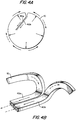
- the present invention indicates that by fabricating the circuit ring 10 using copper tubing that is generally rectangular in cross section and the circuit ring 10 is substantially circular, not only allows the use of direct internal water cooling of the circuit rings but also reduces the size requirements for such rings.
- the disclosed embodiment therefore, allows more space between the insulation and the joint at the circuit lead and permits the circuit lead clips to be brazed rather than bolted to the circuit ring.
- the tubing ends 40a and 40b form an elongated bus bar integral with the circuit ring thereby eliminating a high current, bolted joint, thus resulting in a single assembly.
- the tubing is generally rectangular in cross section, other cross sectional forms may be used.
- the formation of the integral circuit ring-bus bar from hollow copper tubing of a rectangular cross section is in many respects much simpler than machining the prior art circuit rings from copper plates and subsequently forming the bolted joint with the bus bar.
- the electric current would continue to enter the ring at a number of peripheral locations by way of connections from the circuit leads. Additionally, the current would continue to peripherally pass around the ring but would exit at the two parallel portions (40a and 40b) of the copper tubing forming the bus bar and without passing through a joint between the bus bar and circuit ring.
- the coolant which in the presently preferred embodiment is water, it enters one end of the copper tubing through a hydraulic clip (not shown) and travels circumferentially through the ring exiting at the other end of the tubing such as at 40a into the same hydraulic clip.
- FIGS 5A and 5B illustrate the presently preferred embodiment for forming a joint between the circuit ring and one of the circuit leads.
- the water cooled circuit ring of the present invention is significantly smaller than that of the prior art circuit ring .
- a copper adaptor 80 is used in forming the joint between the present hollow copper tubing ring and the prior art circuit lead and clip.
- the adaptor is illustrated as having an "I" shape, it may have any suitable shape and is brazed at 50 to the inner diameter of the circuit ring 10 before placement of the ring and its affixed adaptors in the electromagnetic machine. Since the insulation 60 and 70 is not present when brazing the adaptor to the ring, no high temperature damage to the insulation occurs.
- insulation 70 is substantially shorter than insulation 7 and, therefore, is not located near the brazed joint 55 when the clip 5 is affixed to the copper adaptor 80 after the ring is installed in the machine.
- the presently preferred embodiment employs copper tubing in circuit rings in such a manner as to greatly reduce the size of the circuit ring.
- the brazed adaptors disclosed herein form a circuit ring extension to which circuit leads and their clips may be brazed rather than bolted.
- the elements can be brazed without risk of damaging the insulation between rings.
- the preferred embodiment produces an integral circuit ring and bus bar whereby the single assembly performs the several functions of the prior art elements.
- the copper tubing used in this invention may also be used in a beneficial manner in induction heating apparatus where during the operation of such apparatus cooling water is circulated through the tubes.
Landscapes
- Engineering & Computer Science (AREA)
- Power Engineering (AREA)
- Manufacturing & Machinery (AREA)
- Motor Or Generator Cooling System (AREA)
- Windings For Motors And Generators (AREA)
- Motor Or Generator Frames (AREA)
- Installation Of Bus-Bars (AREA)
Applications Claiming Priority (2)
| Application Number | Priority Date | Filing Date | Title |
|---|---|---|---|
| US564638 | 1983-12-22 | ||
| US07/564,638 US5055729A (en) | 1990-08-09 | 1990-08-09 | Integral water-cooled circuit ring/bus bar assembly for high frequency generators |
Publications (2)
| Publication Number | Publication Date |
|---|---|
| EP0470844A2 true EP0470844A2 (de) | 1992-02-12 |
| EP0470844A3 EP0470844A3 (en) | 1993-06-30 |
Family
ID=24255293
Family Applications (1)
| Application Number | Title | Priority Date | Filing Date |
|---|---|---|---|
| EP19910307296 Withdrawn EP0470844A3 (en) | 1990-08-09 | 1991-08-08 | Circuit ring/bus bar assembly |
Country Status (5)
| Country | Link |
|---|---|
| US (1) | US5055729A (de) |
| EP (1) | EP0470844A3 (de) |
| JP (1) | JPH05111205A (de) |
| CN (1) | CN1058864A (de) |
| MX (1) | MX9100598A (de) |
Cited By (1)
| Publication number | Priority date | Publication date | Assignee | Title |
|---|---|---|---|---|
| EP0756775A4 (de) * | 1994-04-20 | 1998-11-11 | Sundstrand Corp | Geschalteter reluktanz-starter/generator |
Families Citing this family (12)
| Publication number | Priority date | Publication date | Assignee | Title |
|---|---|---|---|---|
| US5270598A (en) * | 1992-04-15 | 1993-12-14 | Westinghouse Electric Corp. | Solid connector for stator phase winding and method of assembly |
| US5281877A (en) * | 1992-11-13 | 1994-01-25 | General Electric Company | Dynamoelectric machine rotor endwindings with corner cooling passages |
| US5325007A (en) * | 1993-01-27 | 1994-06-28 | Sundstrand Corporation | Stator windings for axial gap generators |
| US5859482A (en) * | 1997-02-14 | 1999-01-12 | General Electric Company | Liquid cooled electric motor frame |
| US6570290B2 (en) * | 2001-06-29 | 2003-05-27 | General Electric Company | Single layer interspersed concentric stator winding apparatus and method |
| EP2161819A1 (de) * | 2008-09-08 | 2010-03-10 | Converteam Technology Ltd | Baugruppen für elektrische Maschinen |
| JP2010130803A (ja) * | 2008-11-28 | 2010-06-10 | Jtekt Corp | 多相交流モータ及び電動パワーステアリング装置 |
| WO2012114176A1 (es) * | 2011-02-23 | 2012-08-30 | G2M Ingeniería Ltda | Barra conductora intercelda y/o de alimentación de cobre enfriada utilizada en procesos electrolíticos |
| JP5945813B2 (ja) * | 2011-10-13 | 2016-07-05 | パナソニックIpマネジメント株式会社 | 車両用駆動装置 |
| KR101376224B1 (ko) * | 2013-11-15 | 2014-03-28 | 주식회사 해강알로이 | 발전기용 패러럴 링 |
| FR3110039B1 (fr) * | 2020-05-07 | 2023-07-07 | EN Moteurs | Machine électrique polyphasée équipée d'un dispositif de refroidissement |
| CN113270835B (zh) * | 2021-05-25 | 2022-04-29 | 中广核新能源六安有限公司 | 一种通风散热型塔筒母线槽 |
Family Cites Families (8)
| Publication number | Priority date | Publication date | Assignee | Title |
|---|---|---|---|---|
| US2965775A (en) * | 1958-08-15 | 1960-12-20 | Gen Electric Co Ltd | Dynamo electric machines |
| CH450533A (de) * | 1965-07-14 | 1968-01-31 | Asea Ab | Verfahren zum Herstellen eines ferromagnetischen Nutenkeils für elektrische Maschinen und nach diesem Verfahren hergestellter Nutenkeil |
| US3980910A (en) * | 1974-12-16 | 1976-09-14 | Westinghouse Electric Corporation | Phase lead connector |
| DD123719A1 (de) * | 1976-02-05 | 1977-01-12 | ||
| US4254352A (en) * | 1979-02-28 | 1981-03-03 | Westinghouse Electric Corp. | Parallel ring and ring extension support system for dynamoelectric machines |
| JPS6181151A (ja) * | 1984-09-27 | 1986-04-24 | Toshiba Corp | 回転電機の口出装置 |
| JPS61210852A (ja) * | 1985-03-14 | 1986-09-19 | Toshiba Corp | 回転電機の口出装置 |
| US4982122A (en) * | 1988-05-23 | 1991-01-01 | Westinghouse Electric Corp. | Method and apparatus for insulating liquid-cooled stator coil headers and connectors |
-
1990
- 1990-08-09 US US07/564,638 patent/US5055729A/en not_active Expired - Lifetime
-
1991
- 1991-08-02 JP JP3216558A patent/JPH05111205A/ja not_active Withdrawn
- 1991-08-08 EP EP19910307296 patent/EP0470844A3/en not_active Withdrawn
- 1991-08-08 MX MX9100598A patent/MX9100598A/es unknown
- 1991-08-09 CN CN91105621.1A patent/CN1058864A/zh active Pending
Cited By (1)
| Publication number | Priority date | Publication date | Assignee | Title |
|---|---|---|---|---|
| EP0756775A4 (de) * | 1994-04-20 | 1998-11-11 | Sundstrand Corp | Geschalteter reluktanz-starter/generator |
Also Published As
| Publication number | Publication date |
|---|---|
| JPH05111205A (ja) | 1993-04-30 |
| US5055729A (en) | 1991-10-08 |
| CN1058864A (zh) | 1992-02-19 |
| MX9100598A (es) | 1992-04-01 |
| EP0470844A3 (en) | 1993-06-30 |
Similar Documents
| Publication | Publication Date | Title |
|---|---|---|
| US5489810A (en) | Switched reluctance starter/generator | |
| US5055729A (en) | Integral water-cooled circuit ring/bus bar assembly for high frequency generators | |
| CN105308832B (zh) | 用于高效率机械的液体冷却的定子 | |
| JP5038596B2 (ja) | 一体化冷却系を有するac巻線及びそれを製造する方法 | |
| US9461527B2 (en) | Multiple conductor winding in stator | |
| US3634705A (en) | Cooling system for dynamoelectric machines | |
| EP0461905A2 (de) | Flüssigkeitskühlung des Rotors einer elektrischen Maschine | |
| US3497737A (en) | Connecting means for dynamoelectric machine cooling system | |
| JP5292973B2 (ja) | 回転電機の固定子及び回転電機 | |
| CN1057552A (zh) | 电机定子的冷却系统 | |
| US7564159B2 (en) | Structure of automotive alternator | |
| US3980910A (en) | Phase lead connector | |
| US5103552A (en) | Method of forming an integral water-cooled circuit ring bus bar assembly for high frequency generators | |
| EP4369571A1 (de) | Verbesserte interne kühlsysteme für e-maschinen | |
| US3254246A (en) | Dynamoelectric machines | |
| US4117358A (en) | Combined electrical and coolant distribution system for dynamoelectric machines having internally cooled stator windings | |
| US20240055951A1 (en) | Induction rotor with end ring cooling features | |
| CA2384481C (en) | High temperature superconducting rotor power leads | |
| US4229671A (en) | Multiturn coil for field poles of dynamoelectric machine | |
| US20250309722A1 (en) | Welded high-current connections in dynamoelectric machines | |
| US6798101B1 (en) | Series connector for winding ends of a dynamoelectric machine and associated methods | |
| JP4308672B2 (ja) | バスダクト構体を有する高電力回転変圧器 | |
| US3469127A (en) | Rotor cooling arrangement | |
| EP4113800A1 (de) | Pcb-anschluss | |
| JPH11355992A (ja) | 回転電機 |
Legal Events
| Date | Code | Title | Description |
|---|---|---|---|
| PUAI | Public reference made under article 153(3) epc to a published international application that has entered the european phase |
Free format text: ORIGINAL CODE: 0009012 |
|
| AK | Designated contracting states |
Kind code of ref document: A2 Designated state(s): AT CH DE FR GB IT LI NL SE |
|
| PUAL | Search report despatched |
Free format text: ORIGINAL CODE: 0009013 |
|
| AK | Designated contracting states |
Kind code of ref document: A3 Designated state(s): AT CH DE FR GB IT LI NL SE |
|
| STAA | Information on the status of an ep patent application or granted ep patent |
Free format text: STATUS: THE APPLICATION IS DEEMED TO BE WITHDRAWN |
|
| 18D | Application deemed to be withdrawn |
Effective date: 19930901 |