EP0470845A2 - NMR-Bilderzeugung von chemischen Bestandteilen - Google Patents
NMR-Bilderzeugung von chemischen Bestandteilen Download PDFInfo
- Publication number
- EP0470845A2 EP0470845A2 EP91307297A EP91307297A EP0470845A2 EP 0470845 A2 EP0470845 A2 EP 0470845A2 EP 91307297 A EP91307297 A EP 91307297A EP 91307297 A EP91307297 A EP 91307297A EP 0470845 A2 EP0470845 A2 EP 0470845A2
- Authority
- EP
- European Patent Office
- Prior art keywords
- image
- pixel
- images
- chemical species
- phase
- Prior art date
- Legal status (The legal status is an assumption and is not a legal conclusion. Google has not performed a legal analysis and makes no representation as to the accuracy of the status listed.)
- Withdrawn
Links
Images


Classifications
-
- G—PHYSICS
- G01—MEASURING; TESTING
- G01R—MEASURING ELECTRIC VARIABLES; MEASURING MAGNETIC VARIABLES
- G01R33/00—Arrangements or instruments for measuring magnetic variables
- G01R33/20—Arrangements or instruments for measuring magnetic variables involving magnetic resonance
- G01R33/44—Arrangements or instruments for measuring magnetic variables involving magnetic resonance using nuclear magnetic resonance [NMR]
- G01R33/48—NMR imaging systems
- G01R33/4828—Resolving the MR signals of different chemical species, e.g. water-fat imaging
-
- G—PHYSICS
- G01—MEASURING; TESTING
- G01R—MEASURING ELECTRIC VARIABLES; MEASURING MAGNETIC VARIABLES
- G01R33/00—Arrangements or instruments for measuring magnetic variables
- G01R33/20—Arrangements or instruments for measuring magnetic variables involving magnetic resonance
- G01R33/44—Arrangements or instruments for measuring magnetic variables involving magnetic resonance using nuclear magnetic resonance [NMR]
- G01R33/48—NMR imaging systems
- G01R33/483—NMR imaging systems with selection of signals or spectra from particular regions of the volume, e.g. in vivo spectroscopy
- G01R33/485—NMR imaging systems with selection of signals or spectra from particular regions of the volume, e.g. in vivo spectroscopy based on chemical shift information [CSI] or spectroscopic imaging, e.g. to acquire the spatial distributions of metabolites
Definitions
- This invention relates to nuclear magnetic resonance (NMR) imaging methods and apparatus and more particularly to a method and system for producing separate images of different chemical species using such imaging methods.
- NMR nuclear magnetic resonance
- a uniform magnetic field B0 is applied to an imaged object along the z axis of a Cartesian coordinate system, the origin of which is within the imaged object.
- the effect of the magnetic field B0 is to align the object's nuclear spins along the z axis.
- ⁇ is the Larmor frequency
- ⁇ is the gyromagnetic ratio which is a property of the particular nucleus.
- Water because of its relative abundance in biological tissue and the properties of its proton nuclei, is of principle concern in such imaging.
- the value of the gyromagnetic ratio ⁇ for protons in water is 4.26 kHz/Gauss and therefore in a 1.5 Tesla polarizing magnetic field B0, the resonant or Larmor frequency of water protons is approximately 63.9 MHz.
- the Larmor frequency of protons in fat is approximately 203 Hz. higher than that of protons in water in a 1.5 Tesla polarizing magnetic field B0.
- the difference between the Larmor frequencies of such different isotopes or species of the same nucleus, viz., protons, is termed chemical shift, reflecting the differing chemical environments of the two species.
- a z axis magnetic field gradient G z is applied at the time of the RF pulse so that only the nuclei in a slice through the object in an x-y plane are excited into resonance.
- magnetic field gradients are applied along the x and y axes and an NMR signal is acquired.
- the gradient along the x axis, G x causes the nuclei to precess at different resonant frequencies depending on their position along the x axis; that is, G x spatially encodes the precessing nuclei by frequency.
- the y axis gradient, G y is incremented through a series of values and encodes y position into the rate of change of phase as a function of G y gradient amplitude, a process typically referred to as phase encoding.
- an image may be derived according to well known reconstruction techniques.
- a general description of one such image reconstruction technique based on the Fourier transform is contained in the book "Magnetic Resonance Imaging, Principles and Applications" by D. N. Kean and M. A. Smith. Images in other orientations can be generated by rotation of the gradient directions, as is well known in the art.
- the NMR image into its several chemical shift components.
- protons which will be used hereafter for illustration, it maybe desired to portray as separate images the water and fat components of the subject.
- One method of accomplishing this is to acquire two images S0, and S ⁇ 1 with the fat and water components of the images in phase, and out of phase by ⁇ radians, respectively (the "Dixon” technique). Adding and subtracting these images provides separate fat and water images.
- the phase shift between the fat and water components of the images may be controlled by timing the RF pulses of the NMR sequence so that the signal from the fat image evolves in phase with respect to the water by the proper angle of exactly ⁇ , before the NMR signal is acquired.
- the frequency of the RF transmitter is adjusted to match the Larmor frequency of the water. If the polarizing magnetic field B0 is uniform, this resonance condition is achieved through out the entire subject. Similarly, the out-of-phase condition ( ⁇ radians) for the fat component is achieved for all locations in the subject under homogeneous field conditions. In this case, the decomposition into the separate images is ideal in that fat is completely suppressed in the water image, and vice versa.
- Field inhomogeneities may result from improper adjustment or shimming of the polarizing magnetic field B0, but are more typically the result of "demagnetization" effects caused by the variations in magnetic susceptibility of the imaged tissue, such as between soft tissue and air, or bone and soft tissue, which locally distort the polarizing magnetic field B0.
- demagnetization effects may be of short spatial extent but of high magnitude, and therefore may not be removed by conventional linear or higher order shimming techniques.
- the influence of demagnetization may be accommodated, however, by an imaging technique that uses three images S0, S1, and S ⁇ 1, with the phase evolution times adjusted so that the fat and water components of the images in phase, out of phase by ⁇ , and out of phase by - ⁇ respectively.
- phase shift ⁇ is caused by the unknown resonance offset that results from B0 heterogeneity.
- the phase offset ⁇ 0 may be eliminated from equations (2)-(4) from S0, since the ⁇ i values are real quantities, by determining its argument ⁇ 0.
- the values of ⁇ 1 and ⁇ 2 may be determined from the measured values of S ′ 0 , S ′ 1 and S ′ -1 according to equations (2′)-(4′) as:
- s is a "switch function" which may be either +1 or -1 thus determining the sign of the square root.
- the present invention provides a method and system for determining the value of the switch function for each pixel necessary to unambiguiously decompose an NMR image into separate images of different chemical species.
- the switch function is determined from the phase angle of a B0 image, the phase angle normally being subject to "wrap around" every 2 ⁇ radians.
- the present invention provides two methods of detecting and correcting this wrap around. These methods are preferably used as a first and second step in decomposing the NMR image.
- the first method removes low spatial order phase shifts from the B0 image by fitting to and subtracting a low order polynomial from the B0 image. Occurrences of wrap arounds are reduced because the dynamic range of the resulting phase image is reduced.
- the fitting of the low order surface to the continuous portions of the B0 image may be done by spatially differentiating the B0 image to produce a differentiated image and producing a weighting function by comparing the value of the differentiated image at each pixel to a predetermined threshold and setting the weighting function for that pixel equal to zero if that threshold is passed for the purpose of identifying and discarding discontinuous wrap-around points.
- a differentiated polynomial may be fit to the differentiated B0 image using the weighting function in a weighted curve fitting process. This differentiated polynomial is then integrated to produce the low order surface.
- the differentiation of the B0 image makes the wrap around points easy to identify and the low order surface provides a baseline for subtracting from the B0 image to reduce the wrap around problem.
- the second method of correcting the B0 image which may follow the first method, predicts the phase of successive pixels from previous pixels. Wrap arounds are detected by differences between the predicted value and the actual value of the phase of that pixel.
- a starting pixel in the B0 image is used for an initial phase value.
- the phase value of a neighbor pixel is predicted and compared to the actual phase value of the neighbor pixel. If the predicted value differs from the actual value by more than a predetermined threshold, the phase of the neighbor pixel is corrected by 2 ⁇ to produce a corrected phase value. This process is repeated until a corrected phase value has been obtained over the entire image.
- an NMR imaging system of a type suitable for the practice of the invention includes a computer 10 which controls gradient coil power amplifiers 14 through a pulse control module 12.
- the pulse control module 12 and the gradient amplifiers 14 together produce the proper gradient waveforms G x , G y , and G z , as will be described below, for a spin echo pulse sequence.
- the gradient waveforms are connected to gradient coils 40 which are positioned around the bore of the magnet 34 so that gradients G x , G y , and G z are impressed along their respective axes on the polarizing magnetic field B0 from magnet 34.
- the pulse control module 14 also controls a radio frequency synthesizer 18 which is part of an RF transceiver system, portions of which are enclosed by dashed line block 36.
- the pulse control module 12 also controls a RF modulator 20 which modulates the output of the radio frequency synthesizer 18.
- the resultant RF signals amplified by power amplifier 22 and applied to RF coil 26 through transmit/receive switch 24, are used to excite the nuclear spins of the imaged object (not shown).
- the NMR signals from the excited nuclei of the imaged object are picked up by the RF coil 26 and presented to preamplifier 28 through transmit/receive switch 24, to be amplified and then processed by a quadrature phase detector 30.
- the detected signals are digitized by an high speed A/D converter 32 and applied to computer 10 for processing to produce NMR images of the object.
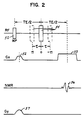
- a spin echo pulse sequence begins with the transmission of a narrow bandwidth radio frequency (RF) pulse 50.
- the energy and the phase of this initial RF pulse 50 may be controlled such that at its termination, the magnetic moments of the individual nuclei are precessing around the z axis within the x-y plane.
- a pulse of such energy and duration is termed a 90° RF pulse.
- the precessing spins begin to dephase according to their chemical shifts which cause the spins of certain chemical species to precess faster than others.
- a 180° RF pulse 54 may be applied which has the effect of rephasing the spins to produce a spin echo 56 at time TE after the 90° RF pulse 50. This spin echo signal 56 is acquired during a read out gradient 53.
- a dephaser pulse 52 is applied after the 90° RF pulse but before the read out gradient to center the spin echo within the read out gradient.
- the fat and water proton spins With the 180° RF pulse 54 centered at time TE/2 the fat and water proton spins will be completely rephased and hence have no phase shift with respect to each other at the time of the spin echo 56. This timing produces an S0 signal.
- the time of the 180° pulse 54 may be shifted forward or back by time ⁇ from the time TE/2. In this case, the fat and water proton spins will not be in phase but will be shifted with respect to each other by 2 ⁇ cs , where ⁇ cs is the difference in Larmor frequencies between water and fat. If ⁇ is chosen to equal ⁇ /2 ⁇ cs then the fat and water proton spins may be shifted by ⁇ and - ⁇ with respect to each other to create an S1 and S ⁇ 1 signal.
- the switch function s is not known.
- the value of S ′ -1 is a known measured quantity, therefore, the relative magnitudes of ⁇ 1 and ⁇ 2, and hence the switch function value, may be determined if ⁇ may be determined.
- ⁇ may be determined from a B0 image equal to S ′ 1 S ′ -1 * provided ⁇ is in the range of ⁇ /2. To extend this range, two techniques are used to detect and correct "wrap arounds" of ⁇ at the values of ⁇ /2. The extended value of ⁇ may be used to determined the switch function.
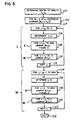
- the first step in determining the value of ⁇ for each pixel is to obtain images S0, S1, and S ⁇ 1 comprised of pixels S0, S1, and S ⁇ 1 per process block 60.
- a B0 image ⁇ m is then produced, per process block 62, by multiplying the image S1 by the complex conjugate of the image S ⁇ 1 on a pixel by pixel basis and extracting the argument, i.e.
- the B0 image ⁇ m is only uniquely determined if
- the wrap arounds 61 are removed by a two stage process, the first stage as shown in Figures 3 and 4(a)-(c) and the second stage shown in Figures 5-8.
- the B0 image is differentiated to produce differentiated images ⁇ m ⁇ x , ⁇ m ⁇ y .
- the wrap around 61 will appeat as large magnitude, narrow spikes which are readily identified by a thresholding process and given zero weight in the curve fitting to be described below.
- the value x0 and corresponding value y0 are the coordinates of the center of gravity of the image as will be described further below.
- ⁇ f (x,y) a3(x-x0)3 + a2(x-x0)2 + a1(x-x0) + b3(y-y0)3 + b2(y-y0)2 + b1(y-y0) + c
- the value c is set equal to ⁇ m (x0,y0). This polynomial surface conforms to the undifferentiated B0 image ⁇ m without regard to the wrap arounds 61 as shown in Figure 4(a).
- Process blocks 68 and 76 together form a loop containing process blocks 70-74 which sequentially correct each pixel of the B0 image.
- the wrapped around points 61 are now unambiguous and may be detected at decision block 72 which identifies segments of ⁇ having magnitudes of greater than 2 ⁇ , which are corrected at process block 74 by adding or subtracting 2 ⁇ to the values of these segments depending on the sign of ⁇ at these segments.
- a corrected image ⁇ corr is produced equal to ⁇ without the wrap arounds 61.
- the corrected image ⁇ corr (x,y) is halved and ⁇ f (x,y) 2 is added at each pixel at process block 78 in accordance with equations 11 and 15 to produce phase image ⁇ as shown in Figure 4(c).
- phase image ⁇ (x,y) may fail for certain B0 areas where the fitfunction ⁇ f (x,y) is not able to follow the spatially rapid phase changes or when the wrap arounds 61 of phase go beyond 2 ⁇ . For these reasons, the phase image ⁇ (x,y) produced by the above described first stage is operated on by a second stage of the process as will now be described.
- the phase of each pixel of the phase image is predicted by an exponential prediction based on the previous pixels. Deviations between the prediction and the actual measured phase are used to detect previously undetected wrap around points 61 and the "wrapped around" pixels are "unwrapped” by adding or subtracting 2 ⁇ .
- Progressive y-lines are then unwrapped starting from the line at y0 and at point x1 for that line.
- these lines are analyzed at and below the y0-line per the loop formed by process blocks 104 and 112 which sequentially decrements the y value of the line to be unwrapped.
- the maximum phase value x1 on each line is determined as indicated by process block 106 within this loop and the line is unwrapped from the pixel x1 rightward to the image boundary as indicated by arrow II of Figure 8, and by process block 108 of Figure 5, and then leftward from pixel x1 as indicated by arrow III of Figure 8 and process block 110 of Figure 5.
- the next lower y-line is then unwrapped and the process is repeated proceeding in the direction shown by arrow I of Figure 8 according to the loop of process blocks 104 and 112 of Figure 5 as previously described.
- the unwrapping process of process block 108 examines the phase of each pixel on the given y line starting at pixel adjacent to pixel x1. This examination is controlled by a loop formed by process blocks 130 and 150.
- )] ⁇ 0.6 and
- This step is a weighted trend prediction
- ⁇ ′ ave is computed for the corresponding pixels on the preceding y-line as follows:
- next pixel is then examined and the process is repeated per the loop formed by process blocks 130 and 150 as described.
- the switch function may be determined from ⁇ (x,y) immediately after the first stage of the correction process or alternatively the second stage of the correction process may be used alone.
- the technique may be used for chemical species other than fat and water. Accordingly, the present invention is not limited to the preferred embodiment described herein.
Landscapes
- Physics & Mathematics (AREA)
- Spectroscopy & Molecular Physics (AREA)
- High Energy & Nuclear Physics (AREA)
- Condensed Matter Physics & Semiconductors (AREA)
- General Physics & Mathematics (AREA)
- Optics & Photonics (AREA)
- Magnetic Resonance Imaging Apparatus (AREA)
- Medical Treatment And Welfare Office Work (AREA)
- Complex Calculations (AREA)
- Image Processing (AREA)
Applications Claiming Priority (2)
| Application Number | Priority Date | Filing Date | Title |
|---|---|---|---|
| US07/566,199 US5144235A (en) | 1990-08-10 | 1990-08-10 | Method of decomposing nmr images by chemical species |
| US566199 | 1995-12-01 |
Publications (2)
| Publication Number | Publication Date |
|---|---|
| EP0470845A2 true EP0470845A2 (de) | 1992-02-12 |
| EP0470845A3 EP0470845A3 (en) | 1992-08-19 |
Family
ID=24261913
Family Applications (1)
| Application Number | Title | Priority Date | Filing Date |
|---|---|---|---|
| EP19910307297 Withdrawn EP0470845A3 (en) | 1990-08-10 | 1991-08-08 | Nmr imaging of chemical species |
Country Status (3)
| Country | Link |
|---|---|
| US (1) | US5144235A (de) |
| EP (1) | EP0470845A3 (de) |
| JP (1) | JPH0616756B2 (de) |
Cited By (2)
| Publication number | Priority date | Publication date | Assignee | Title |
|---|---|---|---|---|
| EP0851236A1 (de) * | 1996-12-27 | 1998-07-01 | Istituto Trentino Di Cultura | Ein Verfahren und ein automatisches System zur Erstellung der Verteilung des Wassergehaltes und/oder der elektrischen Permittivität aus Bildern erzeugt durch magnetische Resonanz |
| US8027713B2 (en) | 2001-04-11 | 2011-09-27 | Hitachi Medical Corporation | Magnetic resonance imaging apparatus and image processing method |
Families Citing this family (26)
| Publication number | Priority date | Publication date | Assignee | Title |
|---|---|---|---|---|
| US5225781A (en) * | 1990-08-10 | 1993-07-06 | General Electric Company | Robust decomposition of NMR images by chemical species |
| US5321359A (en) * | 1993-03-29 | 1994-06-14 | General Electric Company | Selective imaging among three or more chemical species |
| US5498963A (en) * | 1994-08-05 | 1996-03-12 | General Electric Company | Correction of geometric distortion in MRI phase and phase difference images |
| US5627469A (en) * | 1995-07-31 | 1997-05-06 | Advanced Mammography Systems, Inc. | Separation of fat and water magnetic resonance images |
| US5729140A (en) * | 1996-10-04 | 1998-03-17 | Mayo Foundation For Medical Education And Research | Suppression of artifacts in NMR images by correlation of two NEX acquistions |
| US5783942A (en) * | 1996-12-30 | 1998-07-21 | Bernstein; Matthew A. | Unwrap correction for MR phase data encoding flow-related parameter |
| US6091243A (en) * | 1997-11-13 | 2000-07-18 | The University Of British Columbia | Water-fat imaging with direct phase encoding (DPE) |
| US6016057A (en) * | 1998-04-17 | 2000-01-18 | General Electric Company | System and method for improved water and fat separation using a set of low resolution MR images |
| AUPP340698A0 (en) * | 1998-05-07 | 1998-05-28 | Canon Kabushiki Kaisha | Method and apparatus for highly efficient representation and compression of images |
| US6263228B1 (en) | 1998-08-27 | 2001-07-17 | Toshiba America, Mri, Inc. | Method and apparatus for providing separate water-dominant and fat-dominant images from single scan single point dixon MRI sequences |
| US6548303B2 (en) | 2000-06-23 | 2003-04-15 | Cem Corporation | Method and apparatus for rapid fat content determination |
| US6466014B1 (en) | 2000-08-29 | 2002-10-15 | Ge Medical Systems Global Technology Company, Llc | Suppression of fat signals in MR water images produced in Dixon imaging |
| US6483308B1 (en) | 2000-08-31 | 2002-11-19 | Ge Medical Systems Global Technology Company, Llc | Method and apparatus for processing MRI data acquired with a plurality of coils using dixon techniques |
| US6906515B2 (en) * | 2000-12-28 | 2005-06-14 | Hitachi Medical Corporation | Magnetic resonance imaging device and method |
| US7220591B2 (en) | 2001-12-04 | 2007-05-22 | Cem Corporation | Method and apparatus for rapid fat content determination |
| GB2401467B (en) * | 2003-05-09 | 2006-01-25 | Autoliv Dev | Improvements in or relating to a movable or removable unit for a motor vehicle |
| US6922054B2 (en) * | 2003-08-18 | 2005-07-26 | The Board Of Trustees Of The Leland Stanford Junior University | Steady state free precession magnetic resonance imaging using phase detection of material separation |
| US7187170B1 (en) | 2005-09-13 | 2007-03-06 | The Board Of Trustees Of The Leland Stanford Junior Univeristy | Multiple acquisition phase-sensitive SSFP for species separating in MRI |
| US7375522B2 (en) * | 2006-08-28 | 2008-05-20 | Wisconsin Alumni Research Foundation | Method for aligning multiple MR images acquired with alternating readout gradient |
| CN103140167B (zh) | 2010-09-20 | 2016-01-20 | 皇家飞利浦电子股份有限公司 | 化学物类的磁共振成像 |
| CN103201644B (zh) * | 2010-11-02 | 2015-11-25 | 皇家飞利浦电子股份有限公司 | 表征rf发射链路的方法 |
| US9030201B2 (en) | 2011-01-27 | 2015-05-12 | Siemens Medical Solutions Usa, Inc. | System and method for independent manipulation of a fat and a water component in magnetic resonance imaging |
| DE102011004881B4 (de) * | 2011-03-01 | 2012-10-31 | Siemens Aktiengesellschaft | Verarbeiten von komplexen Bilddaten eines Untersuchungsobjekts mit unterschiedlichen Spin-Spezies in der MR-Bildgebung |
| KR20130049461A (ko) * | 2011-11-04 | 2013-05-14 | 삼성전자주식회사 | 자기 공명 영상 촬상 방법 및 장치 |
| US9256977B2 (en) | 2012-02-01 | 2016-02-09 | Siemens Medical Solutions Usa, Inc. | System for reconstruction of virtual frequency selective inversion MR images |
| US10330757B2 (en) * | 2015-01-21 | 2019-06-25 | Koninklijke Philips N.V. | MRI method for calculating derived values from B0 and B1 maps |
Family Cites Families (7)
| Publication number | Priority date | Publication date | Assignee | Title |
|---|---|---|---|---|
| US4346716A (en) * | 1980-03-31 | 1982-08-31 | M/A Com, Inc. | Microwave detection system |
| US4468621A (en) * | 1982-01-20 | 1984-08-28 | National Research Development Corporation | Investigation of samples by N.M.R. techniques |
| JPS61191949A (ja) * | 1985-02-19 | 1986-08-26 | Toshiba Corp | 磁気共鳴イメ−ジング装置 |
| US4661775A (en) * | 1985-07-15 | 1987-04-28 | Technicare Corporation | Chemical shift imaging with field inhomogeneity correction |
| JPS6373947A (ja) * | 1986-09-18 | 1988-04-04 | 株式会社東芝 | 磁気共鳴イメ−ジング方法 |
| JPH01303137A (ja) * | 1988-05-31 | 1989-12-07 | Yokogawa Medical Syst Ltd | 水,脂肪分離mri装置 |
| US4987371A (en) * | 1989-11-27 | 1991-01-22 | General Electric Company | Method for in-vivo shimming |
-
1990
- 1990-08-10 US US07/566,199 patent/US5144235A/en not_active Expired - Lifetime
-
1991
- 1991-08-08 EP EP19910307297 patent/EP0470845A3/en not_active Withdrawn
- 1991-08-08 JP JP22246991A patent/JPH0616756B2/ja not_active Expired - Fee Related
Cited By (3)
| Publication number | Priority date | Publication date | Assignee | Title |
|---|---|---|---|---|
| EP0851236A1 (de) * | 1996-12-27 | 1998-07-01 | Istituto Trentino Di Cultura | Ein Verfahren und ein automatisches System zur Erstellung der Verteilung des Wassergehaltes und/oder der elektrischen Permittivität aus Bildern erzeugt durch magnetische Resonanz |
| US5995863A (en) * | 1996-12-27 | 1999-11-30 | Instituto Trentino Di Cultura | Method and an automatic system for obtaining water content and electric-permittivity maps from magnetic resonance images |
| US8027713B2 (en) | 2001-04-11 | 2011-09-27 | Hitachi Medical Corporation | Magnetic resonance imaging apparatus and image processing method |
Also Published As
| Publication number | Publication date |
|---|---|
| JPH04288142A (ja) | 1992-10-13 |
| US5144235A (en) | 1992-09-01 |
| EP0470845A3 (en) | 1992-08-19 |
| JPH0616756B2 (ja) | 1994-03-09 |
Similar Documents
| Publication | Publication Date | Title |
|---|---|---|
| EP0470845A2 (de) | NMR-Bilderzeugung von chemischen Bestandteilen | |
| US5225781A (en) | Robust decomposition of NMR images by chemical species | |
| US6147492A (en) | Quantitative MR imaging of water and fat using a quadruple-echo sequence | |
| US6856134B1 (en) | Magnetic resonance imaging with fat-water signal separation | |
| EP1271174B1 (de) | Magnetresonanzbildgebung unter Verwendung von SSFP | |
| EP0490528A1 (de) | Korrektur der magnetischen Kernresonanz-Messwerte ermittelt durch Echoplanar-Technik | |
| US6603990B2 (en) | Separation and identification of water and fat MR images at mid-field strength with reduced T2/T2* weighting | |
| US4987371A (en) | Method for in-vivo shimming | |
| US6064206A (en) | Method of and device for determining a temperature distribution in an object by means of magnetic resonance | |
| EP0265956B1 (de) | Verfahren zur Korrektur der durch Änderung des statischen Magnetfeldes verursachten Positions-Abweichung in NMR-Abbildungsgeräten | |
| US5617028A (en) | Magnetic field inhomogeneity correction in MRI using estimated linear magnetic field map | |
| US5321359A (en) | Selective imaging among three or more chemical species | |
| US5168232A (en) | Method for rapid magnet shimming | |
| EP0152879A2 (de) | Bilderzeugung mittels magnetischer Kernresonanz durch zusammengesetzte Impulse für Zeitumkehr | |
| EP1210614B1 (de) | Verfahren und vorrichtung zur darstellung von bewegungsvorgängen in und an einem objekt mittels phasenmarkierung in der bildgebung mittels magnetischer resonanz | |
| CN1327239C (zh) | 相位分布及相位校正方法和装置以及磁共振成像方法和装置 | |
| US5701074A (en) | Spectral component separation including unwrapping of the phase via a poisson equation utilizing a weighting map | |
| US5627469A (en) | Separation of fat and water magnetic resonance images | |
| EP0649539B1 (de) | Eichung der frequenz für bildabtaster mittels magnetischer resonanz | |
| JPH0370965B2 (de) | ||
| US4871967A (en) | Spectral component separation in mr imaging | |
| US20060261809A1 (en) | Determination of spatial sensitivity profiles of rf coils in magnetic resonance imaging | |
| EP0204320B1 (de) | Verfahren zur Bilderzeugung mittels magnetischer Resonanz | |
| US4706027A (en) | Method for correcting phase errors in magnetic resonance imaging data | |
| EP0347995B1 (de) | Verfahren und Anordnung zur Bestimmung einer Kernspinresonanzverteilung |
Legal Events
| Date | Code | Title | Description |
|---|---|---|---|
| PUAI | Public reference made under article 153(3) epc to a published international application that has entered the european phase |
Free format text: ORIGINAL CODE: 0009012 |
|
| AK | Designated contracting states |
Kind code of ref document: A2 Designated state(s): DE GB |
|
| PUAL | Search report despatched |
Free format text: ORIGINAL CODE: 0009013 |
|
| AK | Designated contracting states |
Kind code of ref document: A3 Designated state(s): DE GB |
|
| 17P | Request for examination filed |
Effective date: 19930303 |
|
| STAA | Information on the status of an ep patent application or granted ep patent |
Free format text: STATUS: THE APPLICATION HAS BEEN WITHDRAWN |
|
| 18W | Application withdrawn |
Withdrawal date: 19930617 |
|
| R18W | Application withdrawn (corrected) |
Effective date: 19930617 |