EP0470865A1 - Spiegelsysteme für Kraftfahrzeuge - Google Patents
Spiegelsysteme für Kraftfahrzeuge Download PDFInfo
- Publication number
- EP0470865A1 EP0470865A1 EP91307386A EP91307386A EP0470865A1 EP 0470865 A1 EP0470865 A1 EP 0470865A1 EP 91307386 A EP91307386 A EP 91307386A EP 91307386 A EP91307386 A EP 91307386A EP 0470865 A1 EP0470865 A1 EP 0470865A1
- Authority
- EP
- European Patent Office
- Prior art keywords
- reflectivity
- level
- input device
- mirror system
- reflective element
- Prior art date
- Legal status (The legal status is an assumption and is not a legal conclusion. Google has not performed a legal analysis and makes no representation as to the accuracy of the status listed.)
- Withdrawn
Links
- 230000004313 glare Effects 0.000 claims abstract description 17
- 238000002310 reflectometry Methods 0.000 claims description 73
- VOXZDWNPVJITMN-ZBRFXRBCSA-N 17β-estradiol Chemical compound OC1=CC=C2[C@H]3CC[C@](C)([C@H](CC4)O)[C@@H]4[C@@H]3CCC2=C1 VOXZDWNPVJITMN-ZBRFXRBCSA-N 0.000 claims 1
- 239000011521 glass Substances 0.000 description 12
- 238000004061 bleaching Methods 0.000 description 3
- 239000004020 conductor Substances 0.000 description 3
- 238000010586 diagram Methods 0.000 description 3
- 210000001072 colon Anatomy 0.000 description 2
- 239000003086 colorant Substances 0.000 description 2
- 238000004040 coloring Methods 0.000 description 2
- 238000010276 construction Methods 0.000 description 2
- 230000035945 sensitivity Effects 0.000 description 2
- 239000005361 soda-lime glass Substances 0.000 description 2
- 238000004804 winding Methods 0.000 description 2
- ZXDDPOHVAMWLBH-UHFFFAOYSA-N 2,4-Dihydroxybenzophenone Chemical compound OC1=CC(O)=CC=C1C(=O)C1=CC=CC=C1 ZXDDPOHVAMWLBH-UHFFFAOYSA-N 0.000 description 1
- BCGCCTGNWPKXJL-UHFFFAOYSA-N 3-(2-cyanoethoxy)propanenitrile Chemical compound N#CCCOCCC#N BCGCCTGNWPKXJL-UHFFFAOYSA-N 0.000 description 1
- WSGYTJNNHPZFKR-UHFFFAOYSA-N 3-hydroxypropanenitrile Chemical compound OCCC#N WSGYTJNNHPZFKR-UHFFFAOYSA-N 0.000 description 1
- GVTGSIMRZRYNEI-UHFFFAOYSA-N 5,10-dimethylphenazine Chemical compound C1=CC=C2N(C)C3=CC=CC=C3N(C)C2=C1 GVTGSIMRZRYNEI-UHFFFAOYSA-N 0.000 description 1
- BQCADISMDOOEFD-UHFFFAOYSA-N Silver Chemical compound [Ag] BQCADISMDOOEFD-UHFFFAOYSA-N 0.000 description 1
- 230000000712 assembly Effects 0.000 description 1
- 238000000429 assembly Methods 0.000 description 1
- 208000003464 asthenopia Diseases 0.000 description 1
- 230000005540 biological transmission Effects 0.000 description 1
- 239000003990 capacitor Substances 0.000 description 1
- 238000006243 chemical reaction Methods 0.000 description 1
- 239000011248 coating agent Substances 0.000 description 1
- 238000000576 coating method Methods 0.000 description 1
- 230000007423 decrease Effects 0.000 description 1
- 238000005516 engineering process Methods 0.000 description 1
- 238000010348 incorporation Methods 0.000 description 1
- AMGQUBHHOARCQH-UHFFFAOYSA-N indium;oxotin Chemical compound [In].[Sn]=O AMGQUBHHOARCQH-UHFFFAOYSA-N 0.000 description 1
- 239000012528 membrane Substances 0.000 description 1
- FIKAKWIAUPDISJ-UHFFFAOYSA-L paraquat dichloride Chemical compound [Cl-].[Cl-].C1=C[N+](C)=CC=C1C1=CC=[N+](C)C=C1 FIKAKWIAUPDISJ-UHFFFAOYSA-L 0.000 description 1
- VLTRZXGMWDSKGL-UHFFFAOYSA-M perchlorate Inorganic materials [O-]Cl(=O)(=O)=O VLTRZXGMWDSKGL-UHFFFAOYSA-M 0.000 description 1
- VLTRZXGMWDSKGL-UHFFFAOYSA-N perchloric acid Chemical compound OCl(=O)(=O)=O VLTRZXGMWDSKGL-UHFFFAOYSA-N 0.000 description 1
- 230000002035 prolonged effect Effects 0.000 description 1
- 230000001105 regulatory effect Effects 0.000 description 1
- 230000004044 response Effects 0.000 description 1
- 238000005204 segregation Methods 0.000 description 1
- 229910052709 silver Inorganic materials 0.000 description 1
- 239000004332 silver Substances 0.000 description 1
- 239000002904 solvent Substances 0.000 description 1
- 239000003381 stabilizer Substances 0.000 description 1
- 239000000758 substrate Substances 0.000 description 1
Images


Classifications
-
- B—PERFORMING OPERATIONS; TRANSPORTING
- B60—VEHICLES IN GENERAL
- B60R—VEHICLES, VEHICLE FITTINGS, OR VEHICLE PARTS, NOT OTHERWISE PROVIDED FOR
- B60R1/00—Optical viewing arrangements; Real-time viewing arrangements for drivers or passengers using optical image capturing systems, e.g. cameras or video systems specially adapted for use in or on vehicles
- B60R1/02—Rear-view mirror arrangements
- B60R1/08—Rear-view mirror arrangements involving special optical features, e.g. avoiding blind spots, e.g. convex mirrors; Side-by-side associations of rear-view and other mirrors
- B60R1/083—Anti-glare mirrors, e.g. "day-night" mirrors
- B60R1/088—Anti-glare mirrors, e.g. "day-night" mirrors using a cell of electrically changeable optical characteristic, e.g. liquid-crystal or electrochromic mirrors
-
- B—PERFORMING OPERATIONS; TRANSPORTING
- B60—VEHICLES IN GENERAL
- B60J—WINDOWS, WINDSCREENS, NON-FIXED ROOFS, DOORS, OR SIMILAR DEVICES FOR VEHICLES; REMOVABLE EXTERNAL PROTECTIVE COVERINGS SPECIALLY ADAPTED FOR VEHICLES
- B60J3/00—Antiglare equipment associated with windows or windscreens; Sun visors for vehicles
- B60J3/04—Antiglare equipment associated with windows or windscreens; Sun visors for vehicles adjustable in transparency
Definitions
- This invention relates generally to mirror systems for vehicles, including mirror systems having controls for adjustment of the reflectance level of one or more mirrors.
- Truck drivers and other professional drivers use their mirrors as a primary driving aid and, as such, use their mirrors to a much greater extent than do ordinary drivers. Because of the primary importance served by the rearview mirrors to professional drivers, such drivers desire greater personal control over operation of the mirror.
- Mirror glare is an especially severe problem for professional drivers who drive for long periods and are more likely to be driving during nighttime hours. Such glare creates eye fatigue which adds to the overall fatigue experienced during long trips. Therefore, what may be a mere annoyance to a casual driver, may be a safety problem for the professional driver.
- Non-professional drivers also often desire greater user control over the reflectance level of the mirrors.
- Remotely actuated mirrors have been provided which allow the driver to actuate a two-state, prism-type mirror between states. While such remotely actuated mirrors put control of the mirror in the hands of the driver, they do little more than duplicate the manual flipping of a conventional mechanical rearview mirror.
- the present invention aims to alleviate these problems of the prior art.
- the invention may be adapted to mirror systems utilising continuously variable reflectance elements such as electrochromic elements.
- the present invention preferably provides a vehicular mirror system that puts a premium on driver comfort. Control over the reflectance level of the mirror is preferably provided to the driver in a manner that is rational and therefore natural to use.
- the invention preferably provides a high level of visibility in the mirrors consistent with the driver's comfort level while providing exceptional glare protection.
- the present invention is preferably embodied in a rearview mirror system for a vehicle having a variable reflective element, with a reflectivity level that is continuously variable, and user level setting means for manually setting the reflectivity level of the reflective element at a comfort value.
- Override means that is responsive to selective actuation upon a glare condition preferably sets the reflectivity level of the reflective element at an override value that is lower than the set comfort value.
- the reflective element is preferably lowered manually by the vehicle driver actuating the override means and is preferably returned to the comfort value upon a second actuation by the user of the override means, or upon the lapse of a predetermined time duration, whichever is the first to occur.
- the invention may be embodied in a mirror system having more than one mirror. If more than one mirror is provided, the desired reflectance values of all mirrors may be individually set with separate level setting means or may be jointly set by a common level setting means. The override of the mirrors may be accomplished jointly with a single actuatable means or individually with separate actuatable means. Such a mirror system may additionally include one or more mirrors which are automatically controlled in a more conventional manner.
- an electrochromic mirror having tandem construction in which a pair of electrochromic devices are optically aligned in tandem, is used as the variable reflectance element.
- the comfort reflectivity level is preferably achieved by alternatingly colouring and bleaching both electrochromic elements with one element bleaching while the other is colouring.
- both elements are preferably concurrently coloured in order to achieve the further reduction in reflectance.
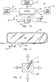
- a mirror system 10 is illustrated as including a driver side mirror 12, typically mounted to the driver's door on the exterior of the vehicle, a passenger side mirror 13 mounted to the exterior of the passenger side door, an interior mirror 14 mounted in the interior of the vehicle and a control 16 for providing signals over output lines 18, 20 and 21 in order to control the respective reflectance level of mirrors 12, 13 and 14 (Figs. 1A-1D).
- mirrors 12, 13 and 14 have reflectance elements with reflectivity levels that are continuously variable over a range of approximately from 6-80%.
- mirrors 12, 13 and 14 are solid-state electrochromic elements such as disclosed in US-A-4712879. This technology is more readily adaptable to large area mirrors, particularly large mirrors of the type used on large trucks, and is very suitable for use as curved mirrors because it requires only a single sheet of glass to bend and it is capable of operation at low reflectivity values for extended periods of time without a segregation of coloration, as occurs with other types of electrochromic elements.
- Mirror system 10 additionally includes a first user selection means 22, which is provided for the purpose of allowing the driver to select a comfortable reflectivity level based upon particular driving conditions and the desires of the driver.
- a first user selection means 22 is provided for the purpose of allowing the driver to select a comfortable reflectivity level based upon particular driving conditions and the desires of the driver.
- the professional driver utilises mirrors as a primary driving aid and will typically select a reflectance level that provides exceptionally good visibility from the mirrors, even if occasional glare levels become somewhat uncomfortable.
- Mirror system 10 additionally includes a second input device 24 that, when actuated, abruptly decreases the reflectivity of the mirrors.
- the second input device provides an override mode, or "panic button,” for quickly responding to excessive glare conditions.
- mirrors 12, 13 and 14 are rapidly coloured to their minimum reflectivity level.
- a second actuation of input device 24 restores control over the reflectivity level of mirrors 12, 13 and 14 to the first input device 22. If the driver does not return the mirrors to their higher reflectivity level after a predetermined period of time, control 16 will automatically do so.
- First user input device 22 is illustrated as a variable potentiometer 26 that allows the user to select from a continuum of reflectivity levels based upon the position of wiper 28. While it may be desirable to allow the driver to select any reflectivity level within the physical capability of mirrors 12, 13 and 14, in a preferred embodiment, variable potentiometer 26 is capable of adjusting the reflectivity of mirrors 12, 13 and 14 in a range of approximately 30-80%. Below approximately 30%, drivers are sometimes unable to clearly discern the shapes of objects viewed in the mirror. Accordingly, it is deemed desirable to limit the driver's choice of a comfort reflectivity setting to a level that maintains good rearward visibility and that provides moderate glare protection. When extreme glaring conditions are experienced, the override mode through input device 24 allows the driver to temporarily relinquish some rear visibility in return for added glare protection.
- an interior mirror 80 includes a variable reflective element 82 mounted within a housing 84.
- first input device 22 is illustrated in the form of a slew-control having momentary switches 86 and 88 which, when activated, cause the reflectance level of the mirror to slew upwardly or downwardly.
- Second input device 24 is illustrated in the form of a single momentary switch 90. Switches 86, 88 and 90 could be mechanical, membrane or capacitive and are typically manually activated. This embodiment of the invention is convenient as an "option" because the entire mirror system, including controls, is packaged in one unit.
- push button switch 30 is integrated with a "joystick" 90 used to adjust the position of the exterior mirrors 12, 14.
- switch 30 could be actuated by pressing axially on the joystick as shown at A.
- first input device 22 is illustrated as a continuously variable potentiometer, it may alternatively be a discrete step switch that selects between a finite number of discrete reflectance levels for the mirror or as a slew-control as illustrated in Figure 4.
- Input devices 22 and 24 could be manually activated, voice activated, touch activated, infrared remotely activated, or any similar device.
- input device 24 could be a rearward facing photodetection means 95 ( Figure 1D) which measures the instantaneous glare causing light level and which, when severe glaring conditions exist, commands the control unit 16 to dim the reflectivity of the mirror system, either to a partial or a minimum reflectivity, from the comfort reflectivity level set by input device 22.
- Figure 1D rearward facing photodetection means 95
- the comfort reflectivity level of mirrors 12, 13 and 14 is jointly established by first input device 22. Upon the experiencing of a glare condition, mirrors 12, 13 and 14 are also simultaneously coloured to a minimum reflectance level by the actuation of a single user input device 24.
- a single input device 22 establishes the comfort reflectance level of mirrors 12, 13 and 14 while separate override devices 24A, 24B and 24C are provided to individually colon mirrors 12 and 14, respectively, to low reflectivity states.
- override devices 24A, 24B and 24C are provided to individually colon mirrors 12 and 14, respectively, to low reflectivity states.
- a resistance-programmable power supply 32 establishes a variable analog voltage on its output lines 18A, 18B extending to mirror 12.
- the value of the analog voltage on lines 18A, 18B is established by the resistance value across lines 34A and 34B that are input lines to power supply 32.
- the resistance between lines 34A and 34B is established by the position of wiper 28 along potentiometer 26 if a switch element 36 is closed, i.e., electrically interconnecting, or shorting, wiper 28 with line 34B. If switch element 36 is open, then the resistance of the main winding of potentiometer 26 establishes the resistance between lines 34A and 34B irrespective of the position of wiper 28.
- switch element 36 The open/closed state of switch element 36 is established by output lines 38A, 38B extending from a switch element control 40.
- Switch element control 40 includes a timer circuit 42 which produces output on lines 38A, 38B and receives inputs on lines 44 extending from a timer control circuit 46.
- Timer control circuit 46 receives its input on lines 48 from a push button debounce circuit 50 which, in turn, is connected with single pole momentary double-throw switch 30.
- Switch element control 40 and resistance-programmable power supply 32 receive regulated DC supply voltage from a power supply 52 that is powered from the vehicle's battery system 54.
- timer 42 produces signals on lines 38A, 38B causing switch element 36 to be closed. This allows the user to select the reflectivity level of mirror 12 by adjusting the position of wiper 28 of potentiometer 26.
- the variable resistance provided by movement of wiper 28 is translated by power supply 32 into a variable analog signal on lines 18A, 18B.
- the driver actuates push button 30.
- timer 42 changes the state of the signal on lines 38A, 38B which causes switch element 36 to open.
- timer 42 is set for 130 seconds but a shorter or longer period may be used.
- control 16 A detailed embodiment of control 16 is illustrated in Figure 3, in which a conventional timer circuit 56, whose time duration is established by a resistor 58 and capacitor 60, is set by the actuation of its set line 62 and reset by actuation of its reset line 64.
- timer circuit 56 produces an output on line 66 that turns a transistor Q1 which turns off, or opens, a transistor Q2.
- Transistors Q1 and Q2 define switch element 36.
- Resistance-programmable power supply 32 produces an output on line 18A that is proportional to the resistance on its input line 34A, which is established by the resistance of potentiometer 26, irrespective of the position of wiper 28, when transistor Q2 is turned off.
- Transistor Q2 is turned on when timer circuit 56 is reset with its output on line 66 at a low level, which causes transistor Q1 to be open and Q2 to be conducting.
- Timer control circuit 46 includes a latch-circuit 70 which produces an output on line 72 when switch 30 is actuated with output 66 in a set state. This produces, in turn, a reset pulse on line 64 to reset timer circuit 56 if it is timing. If timer circuit 56 is not timing, the actuation of switch 30 does not produce a reset pulse on line 64.
- user selectable control 25 includes switches 74, 75 which when closed, short potentiometer 26. This causes the output on lines 18A and 18B to go to the minimum analog output voltage which is a maximum reflectivity condition. Thus, switches 74, 75 serve as day mode switch to place the mirror system 10 in a maximum reflectivity state. When switches 74, 75 are then opened, the reflectivity of the mirror returns to the comfort level previously set by the driver.
- mirrors 12, 13 and 14 are electrochromic mirror assemblies having a pair of electrochromic elements optically aligned in a tandem, back-to-back arrangement as disclosed in commonly-owned, co-pending application Serial No. (Donnelly P-467), filed concurrently herewith, invented by Niall R. Lynam et al . for a PROLONGED COLORATION ELECTROCHROMIC ASSEMBLY, the disclosure of which is hereby incorporated herein by reference and will not be repeated in detail.
- Donnelly P-467 filed concurrently herewith
- three glass elements are used with the two outer glass elements being spaced from the single central glass element to form two cavities which enclose an eletrochromically active solution, thus creating two tandemly aligned single-compartment, self-erasing, solution-phase devices.
- the inwardly facing surfaces of the two outer glass panels and both surfaces of the middle glass substrate are coated with an indium tin oxide transparent conductor coating of high transparency (greater than 80% transmission or thereabouts) and low sheet resistance (in the range 8 to 15 ohms/square or thereabouts).
- the exterior surface of one of the outer glass elements is silver coated to make it reflective when viewed through the remainder of the assembly.
- the two spaces formed between the outer glass elements and the single, middle element is filled with an electrochromically active solution comprising 0.025M methylviologen perchlorate, 0.025M 5,10-dihydro-5,10-dimethylphenazine, 5% wt per volume Uvinul 400 stabiliser from BASF Wyandotte, Wyandotte, Michigan, dissolved in a solvent comprising 50% by volume 3-hydroxypropionitrile and 50% by volume 3,3′-oxydipropionitrile.
- the spacings of the respective outside glass elements from the single, middle glass element are equal and thin with a spacing in the 30 microns to 125 microns range desirable.
- Cyclical application of a user adjustable zero to one volt potential such that the electrochromic solution in one of the spaces colours while that in the other space bleaches, will achieve a comfort reflectivity level in the 15-75% region or thereabouts with the specific reflectance level achieved being principally determined by the voltage selected and the spacing. Thin spacing leads to increased self-erasure which in turn leads to fast bleaching and lower coloration/moderate reflectance.
- a one volt coloration can be concurrently applied across the electrochromic solutions in both spaces such that they both colour simultaneously and rapidly such that a minimum in reflectivity is achieved.
- a suitable choice for the central glass element is 0.71 mm (0.028 inch) soda lime glass coated on both faces with full wave ITO transparent conductors of sheet resistance approximately 8 ohms per square.
- a suitable choice for the outside glass elements is 1.6mm (0.063 inch) soda lime glass, coated on the inwardly facing surface with full wave (8 ohms/square) ITO transparent conductor.
- a suitable spacing is 75 microns or thereabouts.
- a user-defined variable voltage can be applied during the cyclical powering so that a range of partial reflectances for the comfort level can be user selected.
- a one volt potential can be concurrently applied across the two cells to rapidly power both to their fully coloured states and, thereby, achieve a minimum reflectance from the mirror assembly.
- override input device 24 is intended to rapidly force the associated mirrors 12, 13 and 14 to a minimum reflectivity level, it may be desirable to provide a dynamic circuit between power supply 32 and the mirror to increase the rate of coloration of the mirror.
- Such rapid-coloration feature as disclosed in EP-A-0426503 may be especially useful.
- a temporary overshoot may be provided in the voltage supplied on lines 18A, 18B in order to rapidly colour the mirror. The overshoot is of a short enough duration to not damage the mirror.
- Preferred embodiments of the invention include memory means within control 16 such that the comfort setting of the mirror system for various drivers may be stored and called up when that driver is operating the vehicle.
- the input devices could be positioned in a variety of suitable locations, for example, on or adjacent to the steering wheel or the steering column.
- Embodiments of the present invention are not only functional and capable of providing optimum individual control to the driver, but are also natural in their use. Accordingly, its incorporation with other control devices, such as mirror-positioning devices that are already familiar to the driver, tends to cause the features of the invention to become second-nature to the driver with minimum or no instructions. This is especially important when the invention is applied to rental cars or in other applications where driver familiarity with the vehicle cannot be taken for granted. Also, the natural feel to the control will enhance the instinctive reactions of the driver and serve as an extension of the driver's control over the vehicle.
- the mirror system comprises: a variable reflective element having a reflectivity level that is continuously variable within predefined limits; a control circuit having an output port connected with said reflective element for providing a drive signal to establish the reflectivity level of said reflective element; a first user selection means for providing an input signal to said control circuit adapted to establishing a first reflectivity level of said reflective element that is user selectable within a predefined range of reflectivity values; and override means for overriding said first user selection means in order to establish a second reflectivity level of said reflective element irrespective of said first reflectivity level selected with said first user selection means.
- This embodiment preferably includes another variable reflective element having a reflectivity level that is continuously variable within said predefined limit and wherein said control circuit has another output port connected with said another reflective element for providing another drive signal to establish the reflectivity level of said another reflective element, and may include a second user selection means for providing another input signal to said control circuit adapted to establishing a third reflectivity level of said another reflective element that is user selectable within another predefined range of reflectivity values.
- the override means preferably overrides said second user selection means in order to establish said second reflectivity level of said reflective element irrespective of said third reflectivity level selected with said second user selection means.
- the mirror system comprises: a variable reflective element having a reflectivity level that is continuously variable with predefined limits; user level setting means for manually setting the reflectivity level of said reflective element at a desired value; and user actuatable means responsive to a first user actuation for setting the reflectivity level of said reflective element at an override value that is lower than said desired value.
- the user actuable means is responsive to a second user actuation in order to allow the user level setting means to establish the reflectivity level of the reflective element.
Landscapes
- Engineering & Computer Science (AREA)
- Mechanical Engineering (AREA)
- Chemical & Material Sciences (AREA)
- Crystallography & Structural Chemistry (AREA)
- Multimedia (AREA)
- Rear-View Mirror Devices That Are Mounted On The Exterior Of The Vehicle (AREA)
Applications Claiming Priority (2)
| Application Number | Priority Date | Filing Date | Title |
|---|---|---|---|
| US07/565,652 US5122647A (en) | 1990-08-10 | 1990-08-10 | Vehicular mirror system with remotely actuated continuously variable reflectance mirrors |
| US565652 | 1990-08-10 |
Publications (1)
| Publication Number | Publication Date |
|---|---|
| EP0470865A1 true EP0470865A1 (de) | 1992-02-12 |
Family
ID=24259569
Family Applications (1)
| Application Number | Title | Priority Date | Filing Date |
|---|---|---|---|
| EP91307386A Withdrawn EP0470865A1 (de) | 1990-08-10 | 1991-08-12 | Spiegelsysteme für Kraftfahrzeuge |
Country Status (4)
| Country | Link |
|---|---|
| US (1) | US5122647A (de) |
| EP (1) | EP0470865A1 (de) |
| JP (1) | JPH06122344A (de) |
| IE (1) | IE912128A1 (de) |
Cited By (1)
| Publication number | Priority date | Publication date | Assignee | Title |
|---|---|---|---|---|
| GB2297632A (en) * | 1995-01-31 | 1996-08-07 | Prince Corp | Rearview mirror control system |
Families Citing this family (27)
| Publication number | Priority date | Publication date | Assignee | Title |
|---|---|---|---|---|
| US5614885A (en) | 1988-12-05 | 1997-03-25 | Prince Corporation | Electrical control system for vehicle options |
| US5812321A (en) * | 1994-07-19 | 1998-09-22 | Donnelly Corporation | Automatic sensitivity adjustment for electro-optic mirror and headlight activation control |
| AU4153397A (en) | 1996-08-20 | 1998-03-06 | Donnelly Corporation | Window assembly with controllable optical transmission |
| US6089721A (en) * | 1997-04-02 | 2000-07-18 | Donnelly Corporation | Digital electrochromic mirror system |
| US6056410A (en) | 1997-04-02 | 2000-05-02 | Donnelly Corporation | Digital electrochromic mirror system |
| US6317248B1 (en) | 1998-07-02 | 2001-11-13 | Donnelly Corporation | Busbars for electrically powered cells |
| US6520667B1 (en) | 2000-09-15 | 2003-02-18 | Donnelly Corporation | Vehicle interior rearview mirror assembly with display |
| US6759945B2 (en) * | 2001-03-29 | 2004-07-06 | Vtec Technologies, Inc. | Variable transmittance birefringent device |
| US6936807B1 (en) | 2001-09-04 | 2005-08-30 | Exon Science, Inc. | Light-responsive control device of electrochromic rearview mirror system |
| US7167076B2 (en) * | 2001-12-19 | 2007-01-23 | Lear Corporation | Universal garage door operating system and method |
| US7116242B2 (en) | 2002-11-27 | 2006-10-03 | Lear Corporation | Programmable transmitter and receiver including digital radio frequency memory |
| US7300166B2 (en) * | 2003-03-05 | 2007-11-27 | Electrochromix, Inc. | Electrochromic mirrors and other electrooptic devices |
| US20040243627A1 (en) * | 2003-05-28 | 2004-12-02 | Integrated Data Control, Inc. | Chat stream information capturing and indexing system |
| US7039397B2 (en) * | 2003-07-30 | 2006-05-02 | Lear Corporation | User-assisted programmable appliance control |
| US7161466B2 (en) | 2003-07-30 | 2007-01-09 | Lear Corporation | Remote control automatic appliance activation |
| US7183940B2 (en) * | 2003-07-30 | 2007-02-27 | Lear Corporation | Radio relay appliance activation |
| US7183941B2 (en) | 2003-07-30 | 2007-02-27 | Lear Corporation | Bus-based appliance remote control |
| US7084781B2 (en) | 2003-07-30 | 2006-08-01 | Lear Corporation | Programmable vehicle-based appliance remote control |
| US7120430B2 (en) * | 2003-07-30 | 2006-10-10 | Lear Corporation | Programmable interoperable appliance remote control |
| US7269416B2 (en) | 2003-07-30 | 2007-09-11 | Lear Corporation | Universal vehicle based garage door opener control system and method |
| US7088218B2 (en) * | 2003-07-30 | 2006-08-08 | Lear Corporation | Wireless appliance activation transceiver |
| US7068181B2 (en) | 2003-07-30 | 2006-06-27 | Lear Corporation | Programmable appliance remote control |
| US7589613B2 (en) * | 2006-04-03 | 2009-09-15 | Lear Corporation | Trinary to trinary rolling code generation method and system |
| US20090061913A1 (en) * | 2007-08-28 | 2009-03-05 | Michael Woodruff | Cellular telephone with mirror display |
| TWI389458B (zh) * | 2008-04-25 | 2013-03-11 | Leadtrend Tech Corp | 操作模式之判斷裝置及其判斷方法 |
| US8867116B1 (en) | 2013-03-15 | 2014-10-21 | Gentex Corporation | Distate electrochromic device |
| US10479172B2 (en) * | 2018-02-23 | 2019-11-19 | GM Global Technology Operations LLC | Window tinting system and method for a vehicle |
Citations (6)
| Publication number | Priority date | Publication date | Assignee | Title |
|---|---|---|---|---|
| US3840292A (en) * | 1973-09-04 | 1974-10-08 | Gen Motors Corp | Anti-glare rear view mirror incorporating a meltable thermoplastic material |
| US3862798A (en) * | 1973-11-19 | 1975-01-28 | Charles L Hopkins | Automatic rear view mirror adjuster |
| EP0074015A1 (de) * | 1981-09-03 | 1983-03-16 | Gentex Corporation | Ferngesteuerter Rückspiegel für Kraftfahrzeuge |
| DE8615560U1 (de) * | 1986-06-10 | 1986-08-21 | Mittelhäuser, Bernhard, 3002 Wedemark | Innenrückblickspiegel für Kraftfahrzeuge |
| US4701022A (en) * | 1984-11-28 | 1987-10-20 | C-D Marketing, Ltd. | Day/night mirror |
| EP0304198A2 (de) * | 1987-08-21 | 1989-02-22 | General Motors Corporation | Elektrooptische Vorrichtung |
Family Cites Families (41)
| Publication number | Priority date | Publication date | Assignee | Title |
|---|---|---|---|---|
| US3451741A (en) * | 1966-06-15 | 1969-06-24 | Du Pont | Electrochromic device |
| US3521941A (en) * | 1967-02-07 | 1970-07-28 | American Cyanamid Co | Electro-optical device having variable optical density |
| US3578843A (en) * | 1968-09-25 | 1971-05-18 | American Cyanamid Co | Control of light reflected from a mirror |
| US3774988A (en) * | 1969-09-02 | 1973-11-27 | Polaroid Corp | Variable light-filtering device |
| US3708220A (en) * | 1970-05-25 | 1973-01-02 | American Cyanamid Co | High conductivity electrolyte gel materials |
| US3807832A (en) * | 1972-11-09 | 1974-04-30 | American Cyanamid Co | Electrochromic (ec) mirror which rapidly changes reflectivity |
| US4088392A (en) * | 1975-04-13 | 1978-05-09 | American Cyanamid Company | Electrochromic variable optical transmission device with a liquid electrolyte |
| DE2737564C2 (de) * | 1976-09-02 | 1985-05-02 | Matsushita Electric Industrial Co., Ltd., Kadoma, Osaka | Farbanzeigevorrichtung mit an einer Indikatorelektrode entstehenden Redox-Reaktionsprodukten |
| US4201451A (en) * | 1976-09-03 | 1980-05-06 | Donald F. Hassinger | Wide angled rear view mirror apparatus |
| IT1117275B (it) * | 1977-02-25 | 1986-02-17 | Remo Bedini | Metodo e dispositivo automatico per l attenzione dei fenomeni di abbagliamento in luce riflessa |
| JPS5550294A (en) * | 1978-10-09 | 1980-04-11 | Nippon Chemical Ind | Device for driving display unit having storage property |
| JPS5588028A (en) * | 1978-12-27 | 1980-07-03 | Nippon Kogaku Kk <Nikon> | Solid electrochromic element |
| DE2934451A1 (de) * | 1979-08-25 | 1981-03-12 | Vdo Adolf Schindling Ag, 6000 Frankfurt | Abblendbarer rueckspiegel, insbesondere fuer kraftfahrzeuge. |
| JPS57173801A (en) * | 1981-04-21 | 1982-10-26 | Ichikoh Ind Ltd | Reflection factor variable mirror device |
| JPS57208530A (en) * | 1981-06-19 | 1982-12-21 | Ichikoh Ind Ltd | Antidazzling mirror device |
| JPS57208531A (en) * | 1981-06-19 | 1982-12-21 | Ichikoh Ind Ltd | Automatic dazzle-resistant mirror device |
| DE3142909A1 (de) * | 1981-10-29 | 1983-05-11 | Fa. Carl Zeiss, 7920 Heidenheim | Kontinuierliche ladungssteuerung fuer elektrochrome schichten |
| DE3142907A1 (de) * | 1981-10-29 | 1983-05-11 | Fa. Carl Zeiss, 7920 Heidenheim | Optische regelschaltung fuer elektrochrome schichten |
| DE3142906A1 (de) * | 1981-10-29 | 1983-05-11 | Fa. Carl Zeiss, 7920 Heidenheim | Stufenweise ladungssteuerung fuer elektrochrome schichten |
| US4690508A (en) * | 1982-12-15 | 1987-09-01 | C-D Marketing, Ltd. | Liquid crystal closed-loop controlled mirror systems |
| EP0146672B1 (de) * | 1983-11-14 | 1988-10-19 | Nippondenso Co., Ltd. | Betriebsvorrichtung für einen blendungsfreien Flüssigkristallspiegel |
| US4623222A (en) * | 1983-11-14 | 1986-11-18 | Nippondenso Co., Ltd. | Liquid crystal type dazzle-free transmissive-reflective mirror |
| JPS60139545A (ja) * | 1983-12-27 | 1985-07-24 | Nippon Denso Co Ltd | 車両用防眩型反射鏡駆動装置 |
| JPS60148733A (ja) * | 1984-01-12 | 1985-08-06 | Nippon Denso Co Ltd | 車両用防眩型反射鏡駆動装置 |
| JPS60178402A (ja) * | 1984-02-27 | 1985-09-12 | Nippon Denso Co Ltd | ハ−フミラ− |
| JPS60156528U (ja) * | 1984-03-28 | 1985-10-18 | 株式会社東海理化電機製作所 | 防眩ミラ− |
| JPS6154942A (ja) * | 1984-08-27 | 1986-03-19 | Konishiroku Photo Ind Co Ltd | インク貯蔵器 |
| US4645975A (en) * | 1984-09-04 | 1987-02-24 | Ford Motor Company | Composite light pickup device |
| WO1986005148A1 (fr) * | 1985-03-08 | 1986-09-12 | Miroslaw Janowicz | Vehicule automobile avec retroviseur exterieur modifiable |
| DE3516021A1 (de) * | 1985-05-04 | 1986-11-06 | Schott Glaswerke, 6500 Mainz | Elektrochromes system mit dritter elektrode |
| JPS6237247A (ja) * | 1985-05-08 | 1987-02-18 | Nissan Motor Co Ltd | 防眩ミラ− |
| DE3522204A1 (de) * | 1985-06-21 | 1987-01-02 | Anthony Stewart | Rueckspiegel |
| US4781436A (en) * | 1986-03-14 | 1988-11-01 | Armbruster Joseph M | Illuminated feather-touch solenoid actuated vehicle day/night mirror |
| US4793690A (en) * | 1986-07-18 | 1988-12-27 | Donnelly Corporation | Rearview mirror control circuit |
| DE3786621T2 (de) * | 1986-08-25 | 1994-03-17 | Dainippon Screen Mfg | Verfahren und Vorrichtung zur Erzeugung von Bilddaten, die beim Gradationsbildaufzeichnen verwendet werden. |
| EP0280278B1 (de) * | 1987-02-27 | 1994-01-05 | Ichikoh Industries Limited | Vorrichtung zur Steuerung des Reflexionsvermögens eines Elektrochrom-Fahrzeugrückspiegels |
| JP2512880B2 (ja) * | 1987-04-03 | 1996-07-03 | 株式会社ニコン | 第3電極層から電極取出しを行なつたec素子 |
| US4917477A (en) * | 1987-04-06 | 1990-04-17 | Gentex Corporation | Automatic rearview mirror system for automotive vehicles |
| IE59698B1 (en) * | 1987-04-08 | 1994-03-23 | Donnelly Mirrors Ltd | Rearview mirror control circuit |
| JPS63305326A (ja) * | 1987-06-08 | 1988-12-13 | Ichikoh Ind Ltd | 自動車用ec防眩ミラ− |
| US4828361A (en) * | 1987-08-26 | 1989-05-09 | Siegel-Robert, Inc. | Semi-automatic rear view mirror assembly |
-
1990
- 1990-08-10 US US07/565,652 patent/US5122647A/en not_active Expired - Lifetime
-
1991
- 1991-06-20 IE IE212891A patent/IE912128A1/en unknown
- 1991-08-01 JP JP3280959A patent/JPH06122344A/ja active Pending
- 1991-08-12 EP EP91307386A patent/EP0470865A1/de not_active Withdrawn
Patent Citations (6)
| Publication number | Priority date | Publication date | Assignee | Title |
|---|---|---|---|---|
| US3840292A (en) * | 1973-09-04 | 1974-10-08 | Gen Motors Corp | Anti-glare rear view mirror incorporating a meltable thermoplastic material |
| US3862798A (en) * | 1973-11-19 | 1975-01-28 | Charles L Hopkins | Automatic rear view mirror adjuster |
| EP0074015A1 (de) * | 1981-09-03 | 1983-03-16 | Gentex Corporation | Ferngesteuerter Rückspiegel für Kraftfahrzeuge |
| US4701022A (en) * | 1984-11-28 | 1987-10-20 | C-D Marketing, Ltd. | Day/night mirror |
| DE8615560U1 (de) * | 1986-06-10 | 1986-08-21 | Mittelhäuser, Bernhard, 3002 Wedemark | Innenrückblickspiegel für Kraftfahrzeuge |
| EP0304198A2 (de) * | 1987-08-21 | 1989-02-22 | General Motors Corporation | Elektrooptische Vorrichtung |
Cited By (2)
| Publication number | Priority date | Publication date | Assignee | Title |
|---|---|---|---|---|
| GB2297632A (en) * | 1995-01-31 | 1996-08-07 | Prince Corp | Rearview mirror control system |
| GB2297632B (en) * | 1995-01-31 | 1999-05-05 | Prince Corp | Vehicle rearview mirror assembly |
Also Published As
| Publication number | Publication date |
|---|---|
| JPH06122344A (ja) | 1994-05-06 |
| IE912128A1 (en) | 1992-02-12 |
| US5122647A (en) | 1992-06-16 |
Similar Documents
| Publication | Publication Date | Title |
|---|---|---|
| US5122647A (en) | Vehicular mirror system with remotely actuated continuously variable reflectance mirrors | |
| US5148014A (en) | Mirror system with remotely actuated continuously variable reflectant mirrors | |
| US6089721A (en) | Digital electrochromic mirror system | |
| CA2118555C (en) | Anti-glare rearview mirror system | |
| US6099131A (en) | Electro-optic rearview mirror system | |
| US4896030A (en) | Light-reflectivity controller for use with automotive rearview mirror using electrochromic element | |
| JPH08132963A (ja) | 自動防眩ミラー装置 | |
| JP2901489B2 (ja) | 後写鏡 | |
| US6355920B1 (en) | Light-responsive vehicle control such as an electro-optic rearview mirror system that is adaptive to vehicle configuration | |
| DE3722348A1 (de) | Rueckblickspiegelsystem mit kontinuierlich einstellbarer reflexion | |
| JPH11342790A (ja) | 視野拡大ミラー | |
| JPH0114494Y2 (de) | ||
| JPH0518209Y2 (de) | ||
| JPH0714344Y2 (ja) | 温度調節機構付き調光ガラス構造 | |
| JPH0637397Y2 (ja) | 自動車用ec防眩ミラーの自動制御装置 | |
| JP2603131Y2 (ja) | エレクトロクロミックミラー | |
| JPH0223468Y2 (de) | ||
| JPH0641218Y2 (ja) | Ecミラーの光反射率制御装置 | |
| JP3287997B2 (ja) | Ecd防眩ミラー装置 | |
| JPH0738906Y2 (ja) | 自動車用ec防眩ミラーの自動制御装置 | |
| JPH075463Y2 (ja) | オプトエレクトロニック自動防眩ミラー駆動回路 | |
| JPH0635221Y2 (ja) | Ecミラーの光反射率制御装置 | |
| KR20180130710A (ko) | 차량의 유리창 투명도 자동 조절방법 | |
| JPH0533135U (ja) | オプトエレクトロニツク素子を用いた防眩ミラー |
Legal Events
| Date | Code | Title | Description |
|---|---|---|---|
| PUAI | Public reference made under article 153(3) epc to a published international application that has entered the european phase |
Free format text: ORIGINAL CODE: 0009012 |
|
| AK | Designated contracting states |
Kind code of ref document: A1 Designated state(s): DE FR GB IT |
|
| STAA | Information on the status of an ep patent application or granted ep patent |
Free format text: STATUS: THE APPLICATION IS DEEMED TO BE WITHDRAWN |
|
| 18D | Application deemed to be withdrawn |
Effective date: 19920813 |