EP0470879A1 - Differentialübertragungseinrichtung und Kupplung, insbesondere für ein Kraftfahrzeug - Google Patents
Differentialübertragungseinrichtung und Kupplung, insbesondere für ein Kraftfahrzeug Download PDFInfo
- Publication number
- EP0470879A1 EP0470879A1 EP91402068A EP91402068A EP0470879A1 EP 0470879 A1 EP0470879 A1 EP 0470879A1 EP 91402068 A EP91402068 A EP 91402068A EP 91402068 A EP91402068 A EP 91402068A EP 0470879 A1 EP0470879 A1 EP 0470879A1
- Authority
- EP
- European Patent Office
- Prior art keywords
- differential
- output member
- housing
- output
- coupling
- Prior art date
- Legal status (The legal status is an assumption and is not a legal conclusion. Google has not performed a legal analysis and makes no representation as to the accuracy of the status listed.)
- Granted
Links
Images


Classifications
-
- F—MECHANICAL ENGINEERING; LIGHTING; HEATING; WEAPONS; BLASTING
- F16—ENGINEERING ELEMENTS AND UNITS; GENERAL MEASURES FOR PRODUCING AND MAINTAINING EFFECTIVE FUNCTIONING OF MACHINES OR INSTALLATIONS; THERMAL INSULATION IN GENERAL
- F16H—GEARING
- F16H48/00—Differential gearings
- F16H48/06—Differential gearings with gears having orbital motion
- F16H48/08—Differential gearings with gears having orbital motion comprising bevel gears
-
- B—PERFORMING OPERATIONS; TRANSPORTING
- B60—VEHICLES IN GENERAL
- B60K—ARRANGEMENT OR MOUNTING OF PROPULSION UNITS OR OF TRANSMISSIONS IN VEHICLES; ARRANGEMENT OR MOUNTING OF PLURAL DIVERSE PRIME-MOVERS IN VEHICLES; AUXILIARY DRIVES FOR VEHICLES; INSTRUMENTATION OR DASHBOARDS FOR VEHICLES; ARRANGEMENTS IN CONNECTION WITH COOLING, AIR INTAKE, GAS EXHAUST OR FUEL SUPPLY OF PROPULSION UNITS IN VEHICLES
- B60K17/00—Arrangement or mounting of transmissions in vehicles
- B60K17/04—Arrangement or mounting of transmissions in vehicles characterised by arrangement, location or kind of gearing
- B60K17/16—Arrangement or mounting of transmissions in vehicles characterised by arrangement, location or kind of gearing of differential gearing
- B60K17/20—Arrangement or mounting of transmissions in vehicles characterised by arrangement, location or kind of gearing of differential gearing in which the differential movement is limited
-
- B—PERFORMING OPERATIONS; TRANSPORTING
- B60—VEHICLES IN GENERAL
- B60K—ARRANGEMENT OR MOUNTING OF PROPULSION UNITS OR OF TRANSMISSIONS IN VEHICLES; ARRANGEMENT OR MOUNTING OF PLURAL DIVERSE PRIME-MOVERS IN VEHICLES; AUXILIARY DRIVES FOR VEHICLES; INSTRUMENTATION OR DASHBOARDS FOR VEHICLES; ARRANGEMENTS IN CONNECTION WITH COOLING, AIR INTAKE, GAS EXHAUST OR FUEL SUPPLY OF PROPULSION UNITS IN VEHICLES
- B60K17/00—Arrangement or mounting of transmissions in vehicles
- B60K17/34—Arrangement or mounting of transmissions in vehicles for driving both front and rear wheels, e.g. four wheel drive vehicles
- B60K17/344—Arrangement or mounting of transmissions in vehicles for driving both front and rear wheels, e.g. four wheel drive vehicles having a transfer gear
- B60K17/346—Arrangement or mounting of transmissions in vehicles for driving both front and rear wheels, e.g. four wheel drive vehicles having a transfer gear the transfer gear being a differential gear
- B60K17/3462—Arrangement or mounting of transmissions in vehicles for driving both front and rear wheels, e.g. four wheel drive vehicles having a transfer gear the transfer gear being a differential gear with means for changing distribution of torque between front and rear wheels
- B60K17/3465—Arrangement or mounting of transmissions in vehicles for driving both front and rear wheels, e.g. four wheel drive vehicles having a transfer gear the transfer gear being a differential gear with means for changing distribution of torque between front and rear wheels self-actuated means, e.g. differential locked automatically by difference of speed
-
- F—MECHANICAL ENGINEERING; LIGHTING; HEATING; WEAPONS; BLASTING
- F16—ENGINEERING ELEMENTS AND UNITS; GENERAL MEASURES FOR PRODUCING AND MAINTAINING EFFECTIVE FUNCTIONING OF MACHINES OR INSTALLATIONS; THERMAL INSULATION IN GENERAL
- F16D—COUPLINGS FOR TRANSMITTING ROTATION; CLUTCHES; BRAKES
- F16D35/00—Fluid clutches in which the clutching is predominantly obtained by fluid adhesion
- F16D35/005—Fluid clutches in which the clutching is predominantly obtained by fluid adhesion with multiple lamellae
-
- F—MECHANICAL ENGINEERING; LIGHTING; HEATING; WEAPONS; BLASTING
- F16—ENGINEERING ELEMENTS AND UNITS; GENERAL MEASURES FOR PRODUCING AND MAINTAINING EFFECTIVE FUNCTIONING OF MACHINES OR INSTALLATIONS; THERMAL INSULATION IN GENERAL
- F16H—GEARING
- F16H48/00—Differential gearings
- F16H48/06—Differential gearings with gears having orbital motion
- F16H48/10—Differential gearings with gears having orbital motion with orbital spur gears
-
- F—MECHANICAL ENGINEERING; LIGHTING; HEATING; WEAPONS; BLASTING
- F16—ENGINEERING ELEMENTS AND UNITS; GENERAL MEASURES FOR PRODUCING AND MAINTAINING EFFECTIVE FUNCTIONING OF MACHINES OR INSTALLATIONS; THERMAL INSULATION IN GENERAL
- F16H—GEARING
- F16H48/00—Differential gearings
- F16H48/20—Arrangements for suppressing or influencing the differential action, e.g. locking devices
- F16H48/26—Arrangements for suppressing or influencing the differential action, e.g. locking devices using fluid action, e.g. viscous clutches
Definitions
- the present invention relates to differential transmissions used in particular in motor vehicles.
- differentials include an input member and two output members mounted to rotate about the same axis, the two output members being connected, in an exemplary layout, to lateral transmission shafts to the driving wheels of the vehicle.
- the two output members can be connected, respectively, to the input members of two other differentials.
- a first type of self-locking differential comprises at least one friction clutch interposed between two of said input and output members, this clutch being controlled by at least one movable member inside the differential, the position of which depends on the couple transiting through this differential.
- a second attempt to improve the functioning of a differential consisted in associating with it a coupling device with disks and viscous fluid working in shear ("viscocoupler"), interposed between two of said input and output members of the differential.
- viscocoupler viscous fluid working in shear
- Patent application FR-90 05 907 proposes a device which makes it possible to remedy most of these drawbacks and which has a wider range of use than known devices.
- This request relates to a device comprising a differential comprising a housing, an input member and two output members, as well as a controlled slip coupling device, disposed between two of said input and output members; it is characterized in that the differential comprises at least one movable member under the effect of a motor torque whose displacement is used to modify the operating characteristics of the controlled slip coupling device.
- the member mobile is an additional inner casing sliding axially in the main casing and sets of ramps and lugs provided, respectively, on the main and inner casings make it possible to obtain the axial displacement of said inner casing during a relative angular displacement between the two boxes.
- the ramps act on the lugs to move the interior housing in one direction. Stops are also provided for securing in rotation the two housings, during a motor brake torque, without axial displacement of the inner housing.
- the objective sought here consists in obtaining comparable results at lower cost and less bulk.
- the subject of the invention is a transmission device, in particular for a motor vehicle, comprising a differential comprising a housing, an input member and two output members, as well as a coupling device arranged between two of said said input and output members, a differential output member with which the coupling device cooperates being produced in two parts, one of which has teeth and cooperates with at least one other component of the differential, while the second is axially movable over a determined stroke, and is made integral in rotation with an output shaft, means being provided between these two parts to allow a limited angular movement between them and so that a displacement relative angularity between these two parts under the effect of a torque results in an axial displacement of said second part which acts on the coupling device, characterized in that the first part of the output member, which comprises a teeth, is in axial abutment against a part which is itself fixed axially.
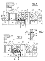
- a differential comprising a housing 10 integral with a crown 11 and constituting the input member of this differential, this housing being rotatably mounted relative to a frame 12, by means of bearings 13 of axis X-X.
- this housing are rotatably mounted around the same axis XX two planetary 14, 15 which constitute the differential output members and which are connected respectively to shafts 16 and 17.
- the housing carries at least one axis 18 planet carrier on which are arranged satellites 19 meshing with the planets 14, 15.
- the sun gear 15 is pressed laterally in a conventional manner against a face 20 of the differential housing.
- the sun gear 14 is produced in two parts 14 a , 14 b .
- the first part 14 a has teeth 21 engaging with the teeth of the satellites 19, and is supported laterally against a face 22 of the housing.
- the second part 14b is made integral with the shaft 16 by means of grooves 23 and it is mounted so as to be able to slide in the direction of the axis XX.
- the two parts 14 a , 14 b of the sun gear respectively have sets of notches 24 and teeth 25 preferably regularly distributed around the periphery of the sleeve 14 b which delimit ramps 26, 27 which cooperate to cause an axial displacement of the sleeve 14 b when a couple transits through the differential.
- the orientation and the slope of these ramps are chosen in such a way that the sleeve 14b is moved to the left, looking at the drawing when a driving torque passes through the differential.
- ramps or stops 28, 29 are involved in transmitting this torque and, depending on the orientation of these ramps or stops, different operating characteristics can be obtained. This is how we have shown in FIG. 2 three possible orientations designated respectively a , b and c .
- a spring constituted by a Belleville washer 30 is interposed between the differential housing and the movable sleeve 14b, and recalls the sleeve clockwise as seen in FIG. 1.
- Seals 31, 32 are further provided between this sleeve on the one hand and the housing and the shaft 16 on the other hand.
- a controlled slip coupling device or viscocoupler 33 is housed inside the housing 10, on the side of the sun gear 14.
- This coupling device is of the type comprising two series of alternating discs, a first series 34 being made integral in rotation by splines of the output shaft 16 associated with the sun gear 14, while the other series 35 of discs is made integral in rotation by means of splines, of the differential housing .
- These discs are immersed in a viscous fluid working in shearing, which can for example be a silicone oil.
- the enclosure containing this fluid is partly delimited by the end of the sleeve 14b .
- the coupling device 33 is only controlled or controlled by the difference in rotational speeds between the housing 10 and the output shaft 16 associated with the sun gear 14.
- the characteristic Cv f ( ⁇ n ) being chosen to be fairly low (where Cv is the resistive torque due to the viscocoupler and ⁇ n the difference in rotational speeds between the housing and the shaft 16), such a differential opposes little reluctance to maneuvers at very low speed.
- the movable portion 14 b of the planetary comprises a radial flange 40 which is supported on at least one shuttle 41 received in a bore 42 of the housing which opens into the chamber of the viscous coupling.
- the connecting means between the two parts of the sun gear are here constituted by notches 43 and lateral dogs 44 delimiting, as in the previous example, ramps 26, 27 and 28, 29. These ramps are represented according to two variants in Figs. 4 A and 4 B.
- An elastic return member constituted by a Belleville washer 45 is here arranged between the two parts which constitute the sun gear and no longer between the differential housing and the movable part of this sun gear.
- this device is entirely comparable to that described above, except that it is the displacement of the or each shuttle which causes a variation in volume and therefore in internal pressure of the viscocoupler.
- the shuttles 41 can come to bear on a movable plate 50 incorporated in the viscocoupler and capable of modifying the spacing between the discs of the latter.
- FIG. 6 There is shown in FIG. 6 an embodiment in which the invention is applied to an inter-bridge differential of the planetary gear type.
- the device comprises a housing 60 in which the differential 61 is arranged, a disc clutch 62 and a toothed belt transmission mechanism 63 ensuring the return to a transmission shaft 64 connected to a front axle.
- the differential comprises a planet carrier 65 which is connected to the input shaft 66, a crown 67 integral in rotation with a flange 68 and an output shaft 69 which constitutes a transmission shaft to a rear axle, and a sun gear connected to a second output shaft 70 coaxial with the input shaft and which is intended to drive the drive shaft 64 towards the front axle.
- the sun gear is made in two parts, a first part 71 mounted free in rotation on the shaft 70 and which is engaged with planet gears 65 a , and a second part 72 which is secured in rotation by splines of the output shaft 70 and which constitutes a thrust plate which can act on the clutch 62.
- Ramp connection means 73, 74 similar to those described with reference to FIG. 3 are provided between the two parts 71 and 72 of the planetary.
- FIG. 7 The operation of a device according to the invention is illustrated in FIG. 7 in which the characteristics of known solutions, of the solution according to the invention and of an "ideal" solution designated by the reference A have been shown on a C / ⁇ n diagram.
- the curves B1 and B2 correspond to solutions of the friction clutch type for two calibrations of different values.
- the curves C1, C2, C3 illustrate three characteristics of known viscocoupler devices.
- Curve D corresponds to the implementation of the invention applied to the control of a viscocoupler, and it can be seen that there is a gradual transition, under engine torque, from the basic characteristic C1 to the extreme characteristic C3 , the end part of the curve D corresponding to the entry into action of stops limiting the axial displacement of the movable sleeve.
- the lower part of the diagram illustrates what happens during engine brake operation. If the ramps involved in this operating situation are parallel to the axis XX, there is a characteristic C′1 symmetrical with the characteristic C1. One can even obtain a characteristic D 'weaker than C′1, if the ramps have an undercut profile, as shown in FIGS. 2 and 4 B.
- the invention allows the blocking phenomenon of the viscocoupler under the effect of an increase in pressure itself resulting from an increase in temperature, this phenomenon being very often sought in order to carry out starts under extreme boundary conditions of low adhesion.
Landscapes
- Engineering & Computer Science (AREA)
- General Engineering & Computer Science (AREA)
- Mechanical Engineering (AREA)
- Chemical & Material Sciences (AREA)
- Combustion & Propulsion (AREA)
- Transportation (AREA)
- Retarders (AREA)
- Motor Power Transmission Devices (AREA)
- Arrangement And Mounting Of Devices That Control Transmission Of Motive Force (AREA)
Applications Claiming Priority (2)
| Application Number | Priority Date | Filing Date | Title |
|---|---|---|---|
| FR9010072 | 1990-08-07 | ||
| FR9010072A FR2666391A1 (fr) | 1990-08-07 | 1990-08-07 | Dispositif de transmission a differentiel et accouplement notamment pour vehicule automobile. |
Publications (2)
| Publication Number | Publication Date |
|---|---|
| EP0470879A1 true EP0470879A1 (de) | 1992-02-12 |
| EP0470879B1 EP0470879B1 (de) | 1993-04-21 |
Family
ID=9399486
Family Applications (1)
| Application Number | Title | Priority Date | Filing Date |
|---|---|---|---|
| EP91402068A Expired - Lifetime EP0470879B1 (de) | 1990-08-07 | 1991-07-24 | Differentialübertragungseinrichtung und Kupplung, insbesondere für ein Kraftfahrzeug |
Country Status (6)
| Country | Link |
|---|---|
| US (1) | US5158507A (de) |
| EP (1) | EP0470879B1 (de) |
| JP (1) | JPH04262150A (de) |
| DE (1) | DE69100067T2 (de) |
| ES (1) | ES2040145T3 (de) |
| FR (1) | FR2666391A1 (de) |
Cited By (1)
| Publication number | Priority date | Publication date | Assignee | Title |
|---|---|---|---|---|
| CN109538728A (zh) * | 2018-12-14 | 2019-03-29 | 重庆宗申创新技术研究院有限公司 | 一种新型电动三轮车差速锁后桥 |
Families Citing this family (10)
| Publication number | Priority date | Publication date | Assignee | Title |
|---|---|---|---|---|
| US5711741A (en) * | 1995-02-27 | 1998-01-27 | Isuzu Motors Limited | Fail safe for toroidal continuous variable transmission |
| JP2002147570A (ja) * | 2000-11-09 | 2002-05-22 | Fuji Heavy Ind Ltd | ディファレンシャル装置の差動制限装置 |
| FR2837756B1 (fr) * | 2002-04-02 | 2004-07-16 | Gkn Automotive Inc | Transmission visqueuse integree dans un differentiel |
| US6780137B1 (en) * | 2002-07-26 | 2004-08-24 | Hydro-Gear Limited Partnership | Differential lock mechanism |
| US6962546B1 (en) | 2002-08-09 | 2005-11-08 | Torque Traction Technologies, Inc. | Limited slip differential using fluid coupling |
| US6817961B2 (en) * | 2003-02-05 | 2004-11-16 | American Axle & Manufacturing, Inc. | Magnetically responsive limited slip differential |
| US20050261101A1 (en) * | 2004-05-24 | 2005-11-24 | Jun Yoshioka | Torque coupling differential assembly with torque disconnect |
| US10391861B2 (en) * | 2016-07-27 | 2019-08-27 | American Axle & Manufacturing, Inc. | Axle assembly with disconnecting differential output |
| US11365795B2 (en) * | 2018-08-22 | 2022-06-21 | Linamar Corporation | Self energizing locking differential |
| WO2021042722A1 (zh) * | 2019-09-04 | 2021-03-11 | 中山大洋电机股份有限公司 | 一种蜗壳组件及其应用的引风机、燃气炉 |
Citations (7)
| Publication number | Priority date | Publication date | Assignee | Title |
|---|---|---|---|---|
| GB925176A (en) * | 1962-02-22 | 1963-05-01 | Dana Corp | Improvements in or relating to a locking differential mechanism |
| GB986817A (en) * | 1959-05-28 | 1965-03-24 | Dana Corp | Improvements in or relating to a locking differential |
| DE1455879A1 (de) * | 1964-05-22 | 1969-09-04 | North American Rockwell | Differential mit begrenztem Schlupf |
| FR2044898A5 (de) * | 1969-05-13 | 1971-02-26 | Nissan Motor | |
| DE3643732A1 (de) * | 1986-12-20 | 1988-07-07 | Audi Ag | Selbstsperrendes ausgleichsgetriebe fuer kraftfahrzeuge |
| US4838119A (en) * | 1986-04-24 | 1989-06-13 | Tochigifujisangyo Kabushiki Kaisha | Differential gear assembly with viscous and friction clutch mechanisms |
| EP0371266A1 (de) * | 1988-11-02 | 1990-06-06 | Carraro S.P.A. | Differentialgetriebe mit Selbstsperrung |
Family Cites Families (16)
| Publication number | Priority date | Publication date | Assignee | Title |
|---|---|---|---|---|
| US3457807A (en) * | 1966-05-05 | 1969-07-29 | Daimler Benz Ag | Self-locking differential gear,especially for motor vehicles |
| US3404585A (en) * | 1966-06-13 | 1968-10-08 | Eaton Yale & Towne | Drive mechanism |
| US3811341A (en) * | 1972-11-08 | 1974-05-21 | Eaton Corp | Differential gear mechanism |
| GB1475141A (en) * | 1974-05-09 | 1977-06-01 | Gkn Transmissions Ltd | Control couplings |
| JPS5634193Y2 (de) * | 1974-10-10 | 1981-08-13 | ||
| GB1498061A (en) * | 1975-02-25 | 1978-01-18 | Gkn Transmissions Ltd | Control couplings and gearing combined therewith |
| US4474080A (en) * | 1978-01-26 | 1984-10-02 | Caterpillar Tractor Co. | Differential with variable torque means |
| US4462272A (en) * | 1981-08-19 | 1984-07-31 | Rockwell International Corporation | Limited slip differential |
| HU195873B (en) * | 1983-11-14 | 1988-07-28 | Magyar Vagon Es Gepgyar | Double-acting differential gear with slip limiting elements |
| EP0193160B1 (de) * | 1985-02-25 | 1992-09-16 | Tochigifujisangyo Kabushikikaisha | Leistungsübertragungsvorrichtung |
| DE3609418A1 (de) * | 1985-03-30 | 1986-10-02 | Zahnradfabrik Friedrichshafen Ag, 7990 Friedrichshafen | Viskosekupplung |
| AT383877B (de) * | 1985-09-16 | 1987-09-10 | Steyr Daimler Puch Ag | Fluessigkeitsreibungskupplung |
| DE3814206A1 (de) * | 1988-04-27 | 1989-11-09 | Viscodrive Gmbh | Selbsttaetig begrenzt sperrendes kegelradausgleichsgetriebe, insbesondere fuer kraftfahrzeuge |
| DE3918565A1 (de) * | 1989-06-07 | 1990-12-13 | Gkn Automotive Ag | Differentialgetriebe |
| DE3920794C1 (de) * | 1989-06-24 | 1990-07-26 | Uni-Cardan Ag, 5200 Siegburg, De | |
| FR2661964B1 (fr) * | 1990-05-11 | 1995-03-17 | Glaenzer Spicer Sa | Dispositif de transmission a differentiel et accouplement a glissement controle. |
-
1990
- 1990-08-07 FR FR9010072A patent/FR2666391A1/fr active Pending
-
1991
- 1991-07-24 EP EP91402068A patent/EP0470879B1/de not_active Expired - Lifetime
- 1991-07-24 DE DE9191402068T patent/DE69100067T2/de not_active Expired - Fee Related
- 1991-07-24 ES ES199191402068T patent/ES2040145T3/es not_active Expired - Lifetime
- 1991-07-31 US US07/738,789 patent/US5158507A/en not_active Expired - Fee Related
- 1991-08-06 JP JP3196617A patent/JPH04262150A/ja not_active Withdrawn
Patent Citations (7)
| Publication number | Priority date | Publication date | Assignee | Title |
|---|---|---|---|---|
| GB986817A (en) * | 1959-05-28 | 1965-03-24 | Dana Corp | Improvements in or relating to a locking differential |
| GB925176A (en) * | 1962-02-22 | 1963-05-01 | Dana Corp | Improvements in or relating to a locking differential mechanism |
| DE1455879A1 (de) * | 1964-05-22 | 1969-09-04 | North American Rockwell | Differential mit begrenztem Schlupf |
| FR2044898A5 (de) * | 1969-05-13 | 1971-02-26 | Nissan Motor | |
| US4838119A (en) * | 1986-04-24 | 1989-06-13 | Tochigifujisangyo Kabushiki Kaisha | Differential gear assembly with viscous and friction clutch mechanisms |
| DE3643732A1 (de) * | 1986-12-20 | 1988-07-07 | Audi Ag | Selbstsperrendes ausgleichsgetriebe fuer kraftfahrzeuge |
| EP0371266A1 (de) * | 1988-11-02 | 1990-06-06 | Carraro S.P.A. | Differentialgetriebe mit Selbstsperrung |
Cited By (1)
| Publication number | Priority date | Publication date | Assignee | Title |
|---|---|---|---|---|
| CN109538728A (zh) * | 2018-12-14 | 2019-03-29 | 重庆宗申创新技术研究院有限公司 | 一种新型电动三轮车差速锁后桥 |
Also Published As
| Publication number | Publication date |
|---|---|
| JPH04262150A (ja) | 1992-09-17 |
| US5158507A (en) | 1992-10-27 |
| DE69100067D1 (de) | 1993-05-27 |
| ES2040145T3 (es) | 1993-10-01 |
| DE69100067T2 (de) | 1993-08-05 |
| FR2666391A1 (fr) | 1992-03-06 |
| EP0470879B1 (de) | 1993-04-21 |
Similar Documents
| Publication | Publication Date | Title |
|---|---|---|
| EP0470879B1 (de) | Differentialübertragungseinrichtung und Kupplung, insbesondere für ein Kraftfahrzeug | |
| FR2646814A1 (fr) | Dispositif d'entrainement pour vehicule automobile | |
| EP0051515A1 (de) | Rotationsservogetriebe, insbesondere für Fahrzeuglenkungen | |
| FR2623581A1 (fr) | Systeme de commande automatique d'un embrayage d'accouplement de deux arbres rotatifs | |
| EP0456563A1 (de) | Übertragungseinrichtung mit Differential und kontrollierte Rutschkupplung | |
| WO2022106681A1 (fr) | Dispositif d'entraînement électrique d'un essieu d'un vehicule | |
| EP0658705B1 (de) | Untersetzungsgetriebe und Kraftübertragung mit zwei Gangstufen für ein Kraftfahrzeug | |
| FR2807478A1 (fr) | Dispositif de deplacement axial pour disques d'embrayage a friction ou de viscocoupleur | |
| FR2728040A1 (fr) | Amortisseur de torsion a mecanisme de transmission intermediaire, notamment pour un embrayage | |
| FR2630800A1 (fr) | Differentiel a roues coniques, a blocage automatique limite, notamment pour vehicules automobiles | |
| EP0143709B1 (de) | Bremsanordnung mit mindestens einer schwimmenden Bremsscheibe | |
| EP0511067A1 (de) | Getriebe mit gesteuerter Flüssigkeitsreibungskupplung, insbesondere für Kraftfahrzeuge | |
| FR2537519A1 (fr) | Systeme d'entrainement pour un mecanisme de rotation, de basculement et de deplacement d'un vehicule, notamment d'un excavateur, comportant un dispositif de freinage | |
| FR2675866A1 (fr) | Dispositif de transmission a viscocoupleur, notamment pour vehicules automobile. | |
| FR2744187A1 (fr) | Dispositif de commande pour un accouplement | |
| EP0321335B1 (de) | Differentialsystem mit veränderlichem gesteuertem Schlupf | |
| EP0366563B1 (de) | Selbstsperrendes Differential | |
| FR2615918A1 (fr) | Systeme de commande automatique d'un embrayage d'accouplement de deux arbres rotatifs | |
| EP0307269B1 (de) | Differentialgetriebe für Motorfahrzeuge | |
| EP0356276B1 (de) | Differentialsystem mit veränderlichem gesteuertem Schlupf | |
| EP0479639A1 (de) | Flüssigkeitsreibungskupplung mit variabler Charakteristik | |
| FR2679303A1 (fr) | Dispositif de transmission a joint articule notamment pour vehicule automobile. | |
| FR2959291A1 (fr) | Differentiel autobloquant | |
| FR2742205A1 (fr) | Dispositif de rattrapage de jeu d'engrenage | |
| FR3134862A1 (fr) | Disque d’embrayage avec dispositif a roue libre comprenant deux systemes de rampes |
Legal Events
| Date | Code | Title | Description |
|---|---|---|---|
| PUAI | Public reference made under article 153(3) epc to a published international application that has entered the european phase |
Free format text: ORIGINAL CODE: 0009012 |
|
| AK | Designated contracting states |
Kind code of ref document: A1 Designated state(s): DE ES FR GB IT |
|
| 17P | Request for examination filed |
Effective date: 19911218 |
|
| 17Q | First examination report despatched |
Effective date: 19920427 |
|
| GRAA | (expected) grant |
Free format text: ORIGINAL CODE: 0009210 |
|
| AK | Designated contracting states |
Kind code of ref document: B1 Designated state(s): DE ES FR GB IT |
|
| GBT | Gb: translation of ep patent filed (gb section 77(6)(a)/1977) |
Effective date: 19930427 |
|
| REF | Corresponds to: |
Ref document number: 69100067 Country of ref document: DE Date of ref document: 19930527 |
|
| PGFP | Annual fee paid to national office [announced via postgrant information from national office to epo] |
Ref country code: DE Payment date: 19930625 Year of fee payment: 3 |
|
| PGFP | Annual fee paid to national office [announced via postgrant information from national office to epo] |
Ref country code: ES Payment date: 19930708 Year of fee payment: 3 |
|
| ITF | It: translation for a ep patent filed | ||
| REG | Reference to a national code |
Ref country code: ES Ref legal event code: FG2A Ref document number: 2040145 Country of ref document: ES Kind code of ref document: T3 |
|
| PLBE | No opposition filed within time limit |
Free format text: ORIGINAL CODE: 0009261 |
|
| STAA | Information on the status of an ep patent application or granted ep patent |
Free format text: STATUS: NO OPPOSITION FILED WITHIN TIME LIMIT |
|
| 26N | No opposition filed | ||
| PG25 | Lapsed in a contracting state [announced via postgrant information from national office to epo] |
Ref country code: ES Free format text: LAPSE BECAUSE OF EXPIRATION OF PROTECTION Effective date: 19940726 |
|
| PG25 | Lapsed in a contracting state [announced via postgrant information from national office to epo] |
Ref country code: DE Effective date: 19950401 |
|
| PG25 | Lapsed in a contracting state [announced via postgrant information from national office to epo] |
Ref country code: GB Effective date: 19950724 |
|
| PGFP | Annual fee paid to national office [announced via postgrant information from national office to epo] |
Ref country code: FR Payment date: 19950727 Year of fee payment: 5 |
|
| GBPC | Gb: european patent ceased through non-payment of renewal fee |
Effective date: 19950724 |
|
| PG25 | Lapsed in a contracting state [announced via postgrant information from national office to epo] |
Ref country code: FR Effective date: 19970328 |
|
| REG | Reference to a national code |
Ref country code: FR Ref legal event code: ST |
|
| REG | Reference to a national code |
Ref country code: ES Ref legal event code: FD2A Effective date: 19990601 |
|
| PG25 | Lapsed in a contracting state [announced via postgrant information from national office to epo] |
Ref country code: IT Free format text: LAPSE BECAUSE OF NON-PAYMENT OF DUE FEES Effective date: 20050724 |