EP0470992B1 - Fernsehsignalüberwachungsgerät - Google Patents
Fernsehsignalüberwachungsgerät Download PDFInfo
- Publication number
- EP0470992B1 EP0470992B1 EP90907206A EP90907206A EP0470992B1 EP 0470992 B1 EP0470992 B1 EP 0470992B1 EP 90907206 A EP90907206 A EP 90907206A EP 90907206 A EP90907206 A EP 90907206A EP 0470992 B1 EP0470992 B1 EP 0470992B1
- Authority
- EP
- European Patent Office
- Prior art keywords
- receiver
- signal
- synchronisation
- phase
- line
- Prior art date
- Legal status (The legal status is an assumption and is not a legal conclusion. Google has not performed a legal analysis and makes no representation as to the accuracy of the status listed.)
- Expired - Lifetime
Links
- 238000001514 detection method Methods 0.000 title claims description 4
- 238000000034 method Methods 0.000 claims abstract description 4
- 238000000926 separation method Methods 0.000 claims description 3
- 239000002131 composite material Substances 0.000 description 3
- 230000004048 modification Effects 0.000 description 3
- 238000012986 modification Methods 0.000 description 3
- 239000003990 capacitor Substances 0.000 description 1
- 239000013256 coordination polymer Substances 0.000 description 1
- 238000010586 diagram Methods 0.000 description 1
Images
Classifications
-
- H—ELECTRICITY
- H04—ELECTRIC COMMUNICATION TECHNIQUE
- H04N—PICTORIAL COMMUNICATION, e.g. TELEVISION
- H04N7/00—Television systems
- H04N7/16—Analogue secrecy systems; Analogue subscription systems
- H04N7/173—Analogue secrecy systems; Analogue subscription systems with two-way working, e.g. subscriber sending a programme selection signal
- H04N7/17309—Transmission or handling of upstream communications
Definitions
- the present invention relates to a television signal detection apparatus for determining which of several television programmes is being displayed at a television receiver.
- a system for television signal detection is known e.g. from DE-A- 3 401 762.
- each hotel room has a television receiver which can be fed with a selection of programmes from a centralised bank of video tape players it is a requirement to log the use of the receiver so that the viewer can be charged for the particular programme selected.
- standard receivers are modified by providing an additional connection between each receiver and a central logging device. Modification of each receiver is clearly expensive. Alternatively a separate switching device is provided at each receiver which also requires additional connections between each receiver and a central logging device.
- Television signal apparatus comprises a remote unit locatable in or in proximity to a television receiver and a central control unit locatable at a position remote from the remote unit, the remote unit having a tuned circuit tuned to the horizontal synchronisation signal frequency of the receiver, a detector circuit for converting the output of the tuned circuit to a modulating signal, and a modulator for frequency modulating a carrier signal, the central control unit having a demodulator arranged to receive the modulated carrier signal and demodulate the carrier signal to produce a signal corresponding to the phase of the receiver horizontal synchronisation signal characteristic of that receiver, the central control unit further having a means to detect the phase of the line synchronisation signal of each of a plurality of video tape players, a comparator to compare the receiver and player synchronisation signals to obtain a match and a microprocessor to log matched signals wherein a header code is joined with the signal corresponding to the phase of the or each receiver synchronisation signal whereby that signal may be identified as characteristic of a particular said receiver.
- a method of logging video output received by a television receiver from a central control unit comprises detecting the horizontal synchronisation signal frequency of the receiver in a unit in or in proximity to the receiver, modulating the detected synchronisation signal and feeding the modulated signal to the central control unit, demodulating the fed signal to produce a signal corresponding to the phase of the receiver horizontal synchronisation signal characteristic of that receiver, detecting the phase of a line synchronisation signal of each or one of a plurality of video players and comparing the receiver and player synchronisation signals to obtain a match and logging matched signals wherein a header code is joined with the signal corresponding to the phase of the or each receiver synchronisation signal whereby that signal may be identified as characteristic of a particular said receiver.
- the characteristics of the apparatus of the invention enable the use of existing coaxial cables between a selected one of the players and a particular receiver to feed detected signals from the remote unit to the central control unit without providing additional cables and without expensive modification of the receiver.
- the remote unit can be fixed in a simple way to the back of the receiver.
- the header code is joined with each signal corresponding to the phase of the or each receiver synchronisation signal so that the signal can be identified as characteristic of a particular said receiver.
- a simple security circuit can be provided in the remote unit to cause an alarm signal to be fed to the central unit in the event of unauthorised removal of a receiver.
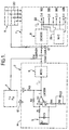
- any number of remote units may be provided depending on the number of television receivers. Only one such unit 2 is shown in Figure 1. Unit 2 is located in close proximity to a television receiver 4 preferably at the rear. A tuned circuit 5 comprising coil L1 and capacitor C1 in unit 2 is tuned to 15625 Hz the horizontal scanning frequency of receiver 4.
- This tuned circuit when the receiver is turned on produces a 15625 Hz sine wave which has a fixed phase relationship to the horizontal scanning activity of the receiver.
- the output of the tuned circuit may vary in amplitude between 10mV and 3V depending upon the make and design of the receiver.
- a zero crossing detector circuit comprising comparator IC1 R1, R2, R3 and C2 converts the output of the tuned circuit to a square wave of amplitude 5V.
- This signal is used to frequency modulate a suitable carrier in modulator 6 to be fed via coaxial cable 10, used to connect a bank of video tape players 9 to receiver 4, to central control unit 7 where the modulated signal is demodulated by demodulator 8.
- the demodulated signal is compared with the phase of the line synchronisation signal of each of a plurality of video tape players 9.
- a header code is joined with the signal corresponding to the phase of the receiver synchronisation signal so that that signal is identified as characteristic of that particular receiver.
- a simple contact switch 12 on a surface of the housing 14 of unit 2 at a point where it is fixed to the outside of receiver 4 enables an alarm to be activated if the receiver 4 is detached from the unit 2. This helps to protect the receiver from unauthorised removal and can be arranged to alert the hotel staff.
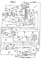
- control unit 7 is shown but with only one video player input 20 and one input 22 from demodulator 8. In a full system several video players and a corresponding number of phase comparator circuits 24 would be provided.
- Each phase comparator circuit 24 is under the control of and provides information to a microprocessor 26.
- microprocessor 26 The exact mode of operation of the microprocessor 26 is not important to a description of circuit function, it is merely necessary to consider the microprocessor as being able to control the state of an enable line 27, a reset line 28 and as being able to count a group of pulses from line 29.
- this comparator circuit 24 is to enable the phase of line synchronisation pulses on line 20 from the video cassette player 9 and demodulated pulses on line 22 from the remote unit 8 to be presented in a digital form to the microprocessor 26.
- a synchronisation separation circuit based around IC2 a dedicated synchronisation separation circuit manufactured by National part No. LM 1881 separates line and field synchronisation pulses from the composite video signal.
- the two outputs from IC2 are a composite synchronisation output (cso) on line 32 and a field synchronisation output (fso) on line 33.
- IC2 thus makes available to subsequent circuitry line and field synchronisation pulses with repetition rates of 15625 and 50 Hz respectively.
- the basic phase comparison is made by a set reset latch IC7, the latch being set by a line synchronisation pulse on line 34 and cleared by a demodulated pulse on line 22, the output of IC7 on line 35 is thus high for a period of time corresponding to the difference in phase between line synchronisation and demodulated pulses.
- the pulses present at the output 29 of IC16 may be counted by the controlling microprocessor 26 so that the microprocessor may determine the phase relationship between line synchronisation and demodulated pulses.
- the set-reset latch IC7 is constantly presented with both line synchronisation pulses and demodulated pulses so that the output on line 35 of this latch is continually changing state at the TV horizontal scan rate of 15625 Hz.
- controlling microprocessor 26 will require an output from the phase comparator and will accordingly take the "enable” line 27 high to the circuit and issue a negative-going reset pulse to the "reset" input on line 28 of the circuit.
- the set-reset latch IC7 is cleared by a reset pulse derived from the controlling microprocessor 26 and set by the arrival of the next field synchronisation pulse.
- the object of this latch IC7 is to cause the output 40 of an AND gate IC8 to remain low, irrespective of the state of its other inputs, until a field synchronisation pulse has occurred.
- IC's 9, 10, 11, 12, 13, 14 & 15 form a "second pulse detector" circuit 42 so that the first output pulse on line 40 from IC8 is ignored, the second output pulse is selected and subsequent output pulses are ignored, thus only the result of the phase comparison made at line 129 is available as the "valid line" input 37 to IC16.
- the second pulse detector circuit 42 functions as follows:-
- the preset/clear latches IC10, IC13 have an initial condition defined by the action of the "ENABLE” input to the circuit. This input acts directly on the active low clear inputs of IC10 and IC13, so that when the "ENABLE" input is taken high the Q output of IC10 is set at a logic O and the Q output of IC13 is set at a logic 1. These outputs are applied directly to the two inputs of the EOR gate IC14, so that the output of IC14 is at a logic level 1.
- the first output pulse from IC8 after inversion by IC9 clocks the active low clock input to IC10, so that the output Q of IC10 assumes a logic 1 after the first pulse.
- Both inputs to IC14 are now at logic level 1 so that its output is at logic level O.
- This output after inversion by IC15 forms the "VALID" output and is also an input to the three input AND gate IC16.
- the second output pulse from IC8 has no further effect on IC10 but is applied to one input of IC11, a two input AND gate, which has as its other input, the Q output of IC10.
- the output of IC11 therefore goes high for the duration of the second output pulse from IC8.
- the output of IC11 is inverted by IC12 and applied to the active low clock input of the preset/clear latch IC13.
- the Q output of IC13 therefore goes low after the second pulse from IC8.
- the third and subsequent pulses from IC8 have no effect on the state of IC13.
- the output of IC14 after inversion by IC16 provides a "VALID" signal which is only TRUE for line 129 of the TV picture field.
- IC's 3 and 4 are part National SN Nos. 7400.
- Latch IC's 5, 7, 10 and 13 are part Nos. 7474.
- Gates IC's 8, 11 and 16 are National SN part Nos. 7411 and IC's 9, 12, 14 and 15 are National SN part Nos. 4LS86.
- the above apparatus will modulate the video TV signals on a UHF carrier suitable for direct reception by a standard TV receiver.
- the horizontal synchronising signal of each video signal is extracted and the phase compared with the phase of the demodulating signal received from the remote unit.
- the comparison method used is sufficiently selective so that a direct and unambiguous output is available as to which if any of the modulated signals is being received by the TV receiver.
- the apparatus according to the invention enables a particular TV channel to which the TV receiver is tuned to be determined at a remote location by control unit 7. No modification is needed for the TV receiver, neither do additional data carrying lines need be required between the control unit and TV receiver.
Landscapes
- Engineering & Computer Science (AREA)
- Multimedia (AREA)
- Signal Processing (AREA)
- Television Systems (AREA)
- Circuits Of Receivers In General (AREA)
- Alarm Systems (AREA)
- Details Of Television Scanning (AREA)
- Radar Systems Or Details Thereof (AREA)
- Testing, Inspecting, Measuring Of Stereoscopic Televisions And Televisions (AREA)
- Selective Calling Equipment (AREA)
- Stereo-Broadcasting Methods (AREA)
- Closed-Circuit Television Systems (AREA)
Claims (7)
- Fernsehsignalüberwachungsgerät mit einer Fernbedieneinheit, die in einem Fernsehempfänger oder in seiner Nähe angeordnet werden kann, und mit einer zentralen Steuereinheit, die an einer von der Fernbedieneinheit entfernten Stelle angeordnet werden kann, wobei die Fernbedieneinheit einen auf die Frequenz des Horizontalsynchronsignals des Empfängers abgestimmten Resonanzkreis aufweist, ferner mit einer Detektorschaltung zum Umsetzen des Ausgangssignals des Resonanzkreises in ein modulierendes Signal und mit einem Modulator zur Frequenzmodulation eines Trägers, wobei die zentrale Steuereinheit einen Demodulator aufweist, der den modulierten Träger empfängt und demoduliert und ein Signal entsprechend der Phase der Empfänger-Horizontalsynchronsignal-charakteristik des Empfängers erzeugt, und wobei die zentrale Steuereinheit außerdem Mittel zum Detektieren der Phase des Zeilensynchronsignals eines jeden einer Vielzahl von Videospielern aufweist, und mit einem Komparator zum Vergleich der Synchronsignale des Empfängers und des Spielers zur Erzielung einer Übereinstimmung sowie mit einem Mikroprozessor zum Registrieren der in Übereinstimmung gebrachten Signale, wobei ein Kopfteil-Code mit dem der Phase des oder jedes Empfänger-Synchronsignals entsprechenden Signal vereinigt wird, wodurch dieses Signal als Kennzeichen eines bestimmten Empfängers identifiziert werden kann.
- Gerät nach Anspruch 1, dadurch gekennzeichnet , daß in der Fernbedieneinheit eine Schutzschaltung vorgesehen ist, die ein der zentralen Einheit zuzuführenden Alarmsignal für den Fall einer unerlaubten Entfernung des Empfängers erzeugt.
- Gerät nach Anspruch 2, dadurch gekennzeichnet , daß der oder jeder Fernsehempfänger eine an ihm befestigte Fernbedieneinheit aufweist und die Schutzschaltung einen Kontaktschalter auf einer Oberfläche der oder jeder Fernbedieneinheit an einer Stelle enthält, an der sie an der Außenseite des Empfängers befestigt ist, wodurch die Trennung der Einheit von ihrem Empfänger einen zu aktivierenden Alarm verursacht.
- Gerät nach einem der Ansprüche 1 - 3, dadurch ge kennzeichnet , daß der Komparator in der Lage ist, die Phase der Zeilensynchronimpulse von dem Videospieler und der demodulierten Impulse von der Fernbedieneinheit in digitaler Form dem Mikroprozessor anzubieten.
- Gerät nach Anspruch 4, dadurch gekennzeichnet , daß der Komparator mit Mitteln versehen ist, die nur die Phase eines Zeilensynchronimpulses und eines demodulierten Impulses je Fernsehhalbbild vergleichen.
- Gerät nach Anspruch 5, dadurch gekennzeichnet , daß die Vergleichsmittel in der Lage sind, die Synchronimpulse bei einer Zeile etwa in der Mitte des Fernsehhalbbildes miteinander zu vergleichen.
- Verfahren zum Registrieren eines Videoausgangssignals, das durch einen Fernsehempfänger von einer zentralen Steuereinheit empfangen wird, dadurch gekennzeichnet , daß die Frequenz des Horizontal-Synchronsignals des Empfängers in einer Einheit in oder in der Nähe des Empfängers detektiert wird, daß das detektierte Synchronsignal moduliert, das modulierte Signal der zentralen Steuereinheit zugeführt und das zugeführte Signal demoduliert wird zur Erzeugung eines Signals, das der Phase der Empfänger-Horizontal-Synchronsignal-Charakteristik des Empfängers entspricht, daß die Phase eines Zeilensynchronsignals jedes oder eines einer Vielzahl von Videospielern detektiert wird und daß die Synchronsignale des Empfängers und des Spielers miteinander verglichen werden, um eine Übereinstimmung und eine Registrierung übereinstimmender Signale zu erzielen, wobei ein Kopfteil-Code mit dem der Phase des oder jedes Empfänger-Synchronsignals entsprechenden Signal vereinigt wird, wodurch dieses Signal als Kennzeichen eines bestimmten Empfängers identifiziert werden kann.
Applications Claiming Priority (3)
| Application Number | Priority Date | Filing Date | Title |
|---|---|---|---|
| GB8910071 | 1989-05-03 | ||
| GB898910071A GB8910071D0 (en) | 1989-05-03 | 1989-05-03 | Television signal detection apparatus |
| PCT/GB1990/000687 WO1990013974A1 (en) | 1989-05-03 | 1990-05-03 | Television signal detection apparatus |
Publications (2)
| Publication Number | Publication Date |
|---|---|
| EP0470992A1 EP0470992A1 (de) | 1992-02-19 |
| EP0470992B1 true EP0470992B1 (de) | 1994-10-12 |
Family
ID=10656094
Family Applications (1)
| Application Number | Title | Priority Date | Filing Date |
|---|---|---|---|
| EP90907206A Expired - Lifetime EP0470992B1 (de) | 1989-05-03 | 1990-05-03 | Fernsehsignalüberwachungsgerät |
Country Status (10)
| Country | Link |
|---|---|
| US (1) | US5294977A (de) |
| EP (1) | EP0470992B1 (de) |
| AT (1) | ATE112917T1 (de) |
| AU (1) | AU644789B2 (de) |
| CA (1) | CA2054751C (de) |
| DE (1) | DE69013341T2 (de) |
| DK (1) | DK0470992T3 (de) |
| ES (1) | ES2064731T3 (de) |
| GB (1) | GB8910071D0 (de) |
| WO (1) | WO1990013974A1 (de) |
Families Citing this family (15)
| Publication number | Priority date | Publication date | Assignee | Title |
|---|---|---|---|---|
| US6675383B1 (en) * | 1997-01-22 | 2004-01-06 | Nielsen Media Research, Inc. | Source detection apparatus and method for audience measurement |
| CA2289519C (en) | 1998-05-12 | 2001-04-10 | Nielsen Media Research, Inc. | Audience measurement system for digital television |
| US7000243B1 (en) | 1998-12-31 | 2006-02-14 | Oncommand Corporation | Allocating computer resources within a video distribution system |
| US7444663B2 (en) | 1998-12-31 | 2008-10-28 | Lodgenet Interactive Corporation | Menuing system for controlling content delivery within a video distribution system |
| US20030131350A1 (en) * | 2002-01-08 | 2003-07-10 | Peiffer John C. | Method and apparatus for identifying a digital audio signal |
| US9711153B2 (en) | 2002-09-27 | 2017-07-18 | The Nielsen Company (Us), Llc | Activating functions in processing devices using encoded audio and detecting audio signatures |
| US8959016B2 (en) | 2002-09-27 | 2015-02-17 | The Nielsen Company (Us), Llc | Activating functions in processing devices using start codes embedded in audio |
| US7222071B2 (en) | 2002-09-27 | 2007-05-22 | Arbitron Inc. | Audio data receipt/exposure measurement with code monitoring and signature extraction |
| US20060167458A1 (en) * | 2005-01-25 | 2006-07-27 | Lorenz Gabele | Lock and release mechanism for a sternal clamp |
| US9015740B2 (en) | 2005-12-12 | 2015-04-21 | The Nielsen Company (Us), Llc | Systems and methods to wirelessly meter audio/visual devices |
| AU2006325808B2 (en) * | 2005-12-12 | 2011-12-15 | The Nielsen Company (Us), Llc | Systems and methods to wirelessly meter audio/visual devices |
| CN101536503B (zh) | 2006-06-15 | 2012-09-26 | 尼尔森(美国)有限公司 | 利用隐藏字幕信息来计量内容曝光的方法和装置 |
| US8019162B2 (en) * | 2006-06-20 | 2011-09-13 | The Nielsen Company (Us), Llc | Methods and apparatus for detecting on-screen media sources |
| US9124769B2 (en) | 2008-10-31 | 2015-09-01 | The Nielsen Company (Us), Llc | Methods and apparatus to verify presentation of media content |
| US9426543B1 (en) * | 2015-12-18 | 2016-08-23 | Vuclip (Singapore) Pte. Ltd. | Server-based video stitching |
Family Cites Families (5)
| Publication number | Priority date | Publication date | Assignee | Title |
|---|---|---|---|---|
| US4057829B1 (en) * | 1973-12-18 | 1995-07-25 | Spectradyne Inc | Communication TV monitoring and control system |
| US4115807A (en) * | 1976-07-19 | 1978-09-19 | Pires H George | Telephone billing apparatus for a subscription television system |
| DE3401762A1 (de) * | 1984-01-19 | 1985-08-01 | FSG Fernseh - System - Gesellschaft mbH, 8042 Oberschleißheim | Anlage zur erfassung des betriebszustandes von fernsehgeraeten |
| AU7061487A (en) * | 1986-03-26 | 1987-10-01 | Nowosielski, J. | Tv channel monitor for television receivers and/or video recorders |
| FR2628588A1 (fr) * | 1988-03-14 | 1989-09-15 | Croquet Cie | Procede et systeme d'acquisition et de transmission d'informations sur l'audience de programmes televises |
-
1989
- 1989-05-03 GB GB898910071A patent/GB8910071D0/en active Pending
-
1990
- 1990-05-03 WO PCT/GB1990/000687 patent/WO1990013974A1/en not_active Ceased
- 1990-05-03 AT AT90907206T patent/ATE112917T1/de not_active IP Right Cessation
- 1990-05-03 DK DK90907206.8T patent/DK0470992T3/da active
- 1990-05-03 AU AU55323/90A patent/AU644789B2/en not_active Ceased
- 1990-05-03 DE DE69013341T patent/DE69013341T2/de not_active Expired - Fee Related
- 1990-05-03 US US07/775,938 patent/US5294977A/en not_active Expired - Fee Related
- 1990-05-03 ES ES90907206T patent/ES2064731T3/es not_active Expired - Lifetime
- 1990-05-03 CA CA002054751A patent/CA2054751C/en not_active Expired - Fee Related
- 1990-05-03 EP EP90907206A patent/EP0470992B1/de not_active Expired - Lifetime
Also Published As
| Publication number | Publication date |
|---|---|
| ES2064731T3 (es) | 1995-02-01 |
| AU5532390A (en) | 1990-11-29 |
| WO1990013974A1 (en) | 1990-11-15 |
| DK0470992T3 (da) | 1994-12-27 |
| AU644789B2 (en) | 1993-12-23 |
| ATE112917T1 (de) | 1994-10-15 |
| US5294977A (en) | 1994-03-15 |
| DE69013341T2 (de) | 1995-03-23 |
| CA2054751C (en) | 1998-07-07 |
| CA2054751A1 (en) | 1990-11-04 |
| DE69013341D1 (de) | 1994-11-17 |
| GB8910071D0 (en) | 1989-06-21 |
| EP0470992A1 (de) | 1992-02-19 |
Similar Documents
| Publication | Publication Date | Title |
|---|---|---|
| AU644789B2 (en) | Television signal detection apparatus | |
| US4100575A (en) | Method of and apparatus for modifying a video signal to prevent unauthorized recording and reproduction thereof | |
| EP0346402B1 (de) | Verfahren und gerät für interaktives video | |
| US4245245A (en) | Interactive CATV system | |
| EP0161512B1 (de) | Programmidentifikationssystem | |
| US3733430A (en) | Channel monitoring system | |
| US5335014A (en) | Method and apparatus for remote synchronous switching of video transmitters | |
| EP0393352A3 (de) | OSD-Mehrnormfernsehempfänger | |
| GB1445456A (en) | Circuit arrangement for generating a control signal for the field output stage in a television receiver | |
| CA1150818A (en) | Subscription television coding system | |
| US4213149A (en) | Apparatus for preventing video tape duplication | |
| KR950005064B1 (ko) | 비데오 레코더용 회로장치 | |
| EP0402992A1 (de) | Übertragungssystem zum Übertragen eines Videosignals mit einem Kennsignal, Sendeanordnung zum Erzeugen des Videosignals und Bildwiedergabeanordnung zum Empfangen und Wiedergeben des Videosignals | |
| JPH0429277B2 (de) | ||
| GB2107550A (en) | Video disc player | |
| EP0119081A2 (de) | Vorrichtung zum Darstellen von verschlüsselten oder entschlüsselten Fernsehsignalen | |
| US4727432A (en) | A VDP timing signal generator producing clock signals in phase with produced video sync signals and displaying the inphase condition | |
| JP3218410B2 (ja) | 送信機の同期切換方法および装置 | |
| KR100272734B1 (ko) | 비디오 신호의 큰 위상 시프트에 영향을 받지 않는 수평 라인 카운터 | |
| US4872053A (en) | Device to control the presence of information of images in video signals | |
| JP2798138B2 (ja) | 文字放送受信機の文字データ分離回路 | |
| JPS63123287A (ja) | 非標準テレビジヨン信号の識別信号伝送方法 | |
| JP2535828B2 (ja) | 信号伝送装置 | |
| JPH01137893A (ja) | 同期圧縮スクランブル装置 | |
| JPH04120891A (ja) | ドアカメラシステム |
Legal Events
| Date | Code | Title | Description |
|---|---|---|---|
| PUAI | Public reference made under article 153(3) epc to a published international application that has entered the european phase |
Free format text: ORIGINAL CODE: 0009012 |
|
| 17P | Request for examination filed |
Effective date: 19911114 |
|
| AK | Designated contracting states |
Kind code of ref document: A1 Designated state(s): AT BE CH DE DK ES FR GB IT LI LU NL SE |
|
| RAP1 | Party data changed (applicant data changed or rights of an application transferred) |
Owner name: FISHER, DAVID |
|
| RIN1 | Information on inventor provided before grant (corrected) |
Inventor name: FISHER, DAVID Inventor name: TYSON, LAWRENCE |
|
| 17Q | First examination report despatched |
Effective date: 19930629 |
|
| GRAA | (expected) grant |
Free format text: ORIGINAL CODE: 0009210 |
|
| AK | Designated contracting states |
Kind code of ref document: B1 Designated state(s): AT BE CH DE DK ES FR GB IT LI LU NL SE |
|
| REF | Corresponds to: |
Ref document number: 112917 Country of ref document: AT Date of ref document: 19941015 Kind code of ref document: T |
|
| REF | Corresponds to: |
Ref document number: 69013341 Country of ref document: DE Date of ref document: 19941117 |
|
| ET | Fr: translation filed | ||
| REG | Reference to a national code |
Ref country code: DK Ref legal event code: T3 |
|
| ITF | It: translation for a ep patent filed | ||
| EAL | Se: european patent in force in sweden |
Ref document number: 90907206.8 |
|
| REG | Reference to a national code |
Ref country code: ES Ref legal event code: FG2A Ref document number: 2064731 Country of ref document: ES Kind code of ref document: T3 |
|
| PLBE | No opposition filed within time limit |
Free format text: ORIGINAL CODE: 0009261 |
|
| STAA | Information on the status of an ep patent application or granted ep patent |
Free format text: STATUS: NO OPPOSITION FILED WITHIN TIME LIMIT |
|
| 26N | No opposition filed | ||
| PGFP | Annual fee paid to national office [announced via postgrant information from national office to epo] |
Ref country code: DE Payment date: 19980421 Year of fee payment: 9 |
|
| PGFP | Annual fee paid to national office [announced via postgrant information from national office to epo] |
Ref country code: SE Payment date: 19980427 Year of fee payment: 9 |
|
| PGFP | Annual fee paid to national office [announced via postgrant information from national office to epo] |
Ref country code: FR Payment date: 19980430 Year of fee payment: 9 |
|
| PGFP | Annual fee paid to national office [announced via postgrant information from national office to epo] |
Ref country code: ES Payment date: 19980504 Year of fee payment: 9 |
|
| PGFP | Annual fee paid to national office [announced via postgrant information from national office to epo] |
Ref country code: DK Payment date: 19980520 Year of fee payment: 9 |
|
| PGFP | Annual fee paid to national office [announced via postgrant information from national office to epo] |
Ref country code: CH Payment date: 19980525 Year of fee payment: 9 |
|
| PGFP | Annual fee paid to national office [announced via postgrant information from national office to epo] |
Ref country code: AT Payment date: 19980526 Year of fee payment: 9 |
|
| PGFP | Annual fee paid to national office [announced via postgrant information from national office to epo] |
Ref country code: NL Payment date: 19980531 Year of fee payment: 9 |
|
| PGFP | Annual fee paid to national office [announced via postgrant information from national office to epo] |
Ref country code: BE Payment date: 19980603 Year of fee payment: 9 |
|
| PGFP | Annual fee paid to national office [announced via postgrant information from national office to epo] |
Ref country code: LU Payment date: 19980604 Year of fee payment: 9 |
|
| PG25 | Lapsed in a contracting state [announced via postgrant information from national office to epo] |
Ref country code: LU Free format text: LAPSE BECAUSE OF NON-PAYMENT OF DUE FEES Effective date: 19990503 Ref country code: AT Free format text: LAPSE BECAUSE OF NON-PAYMENT OF DUE FEES Effective date: 19990503 |
|
| PG25 | Lapsed in a contracting state [announced via postgrant information from national office to epo] |
Ref country code: SE Free format text: LAPSE BECAUSE OF NON-PAYMENT OF DUE FEES Effective date: 19990504 Ref country code: ES Free format text: LAPSE BECAUSE OF EXPIRATION OF PROTECTION Effective date: 19990504 |
|
| PG25 | Lapsed in a contracting state [announced via postgrant information from national office to epo] |
Ref country code: LI Free format text: LAPSE BECAUSE OF NON-PAYMENT OF DUE FEES Effective date: 19990531 Ref country code: DK Free format text: LAPSE BECAUSE OF NON-PAYMENT OF DUE FEES Effective date: 19990531 Ref country code: CH Free format text: LAPSE BECAUSE OF NON-PAYMENT OF DUE FEES Effective date: 19990531 Ref country code: BE Free format text: LAPSE BECAUSE OF NON-PAYMENT OF DUE FEES Effective date: 19990531 |
|
| BERE | Be: lapsed |
Owner name: FISHER DAVID Effective date: 19990531 |
|
| PG25 | Lapsed in a contracting state [announced via postgrant information from national office to epo] |
Ref country code: NL Free format text: LAPSE BECAUSE OF NON-PAYMENT OF DUE FEES Effective date: 19991201 |
|
| REG | Reference to a national code |
Ref country code: CH Ref legal event code: PL |
|
| EUG | Se: european patent has lapsed |
Ref document number: 90907206.8 |
|
| PG25 | Lapsed in a contracting state [announced via postgrant information from national office to epo] |
Ref country code: FR Free format text: LAPSE BECAUSE OF NON-PAYMENT OF DUE FEES Effective date: 20000131 |
|
| NLV4 | Nl: lapsed or anulled due to non-payment of the annual fee |
Effective date: 19991201 |
|
| PG25 | Lapsed in a contracting state [announced via postgrant information from national office to epo] |
Ref country code: DE Free format text: LAPSE BECAUSE OF NON-PAYMENT OF DUE FEES Effective date: 20000301 |
|
| REG | Reference to a national code |
Ref country code: FR Ref legal event code: ST |
|
| REG | Reference to a national code |
Ref country code: DK Ref legal event code: EBP |
|
| REG | Reference to a national code |
Ref country code: ES Ref legal event code: FD2A Effective date: 20010601 |
|
| REG | Reference to a national code |
Ref country code: GB Ref legal event code: IF02 |
|
| PGFP | Annual fee paid to national office [announced via postgrant information from national office to epo] |
Ref country code: GB Payment date: 20020503 Year of fee payment: 13 |
|
| PG25 | Lapsed in a contracting state [announced via postgrant information from national office to epo] |
Ref country code: GB Free format text: LAPSE BECAUSE OF NON-PAYMENT OF DUE FEES Effective date: 20030503 |
|
| GBPC | Gb: european patent ceased through non-payment of renewal fee |
Effective date: 20030503 |
|
| PG25 | Lapsed in a contracting state [announced via postgrant information from national office to epo] |
Ref country code: IT Free format text: LAPSE BECAUSE OF NON-PAYMENT OF DUE FEES;WARNING: LAPSES OF ITALIAN PATENTS WITH EFFECTIVE DATE BEFORE 2007 MAY HAVE OCCURRED AT ANY TIME BEFORE 2007. THE CORRECT EFFECTIVE DATE MAY BE DIFFERENT FROM THE ONE RECORDED. Effective date: 20050503 |