EP0471285A2 - Gegenschwerkraft-Giesseinrichtung und Verfahren unter Anwendung von Vakuum - Google Patents
Gegenschwerkraft-Giesseinrichtung und Verfahren unter Anwendung von Vakuum Download PDFInfo
- Publication number
- EP0471285A2 EP0471285A2 EP91113294A EP91113294A EP0471285A2 EP 0471285 A2 EP0471285 A2 EP 0471285A2 EP 91113294 A EP91113294 A EP 91113294A EP 91113294 A EP91113294 A EP 91113294A EP 0471285 A2 EP0471285 A2 EP 0471285A2
- Authority
- EP
- European Patent Office
- Prior art keywords
- melt
- sprue
- mold
- mold cavity
- chamber
- Prior art date
- Legal status (The legal status is an assumption and is not a legal conclusion. Google has not performed a legal analysis and makes no representation as to the accuracy of the status listed.)
- Withdrawn
Links
Images



Classifications
-
- B—PERFORMING OPERATIONS; TRANSPORTING
- B22—CASTING; POWDER METALLURGY
- B22D—CASTING OF METALS; CASTING OF OTHER SUBSTANCES BY THE SAME PROCESSES OR DEVICES
- B22D18/00—Pressure casting; Vacuum casting
- B22D18/06—Vacuum casting, i.e. making use of vacuum to fill the mould
Definitions
- This invention relates to the vacuum-assisted, countergravity casting of a melt into a gas permeable mold and, more particularly, to a method and apparatus for vacuum-assisted, countergravity casting in such a manner as to drain melt from a mold fill sprue after casting without siphoning melt from the melt-filled mold cavities.
- the vacuum-assisted, countergravity casting apparatus includes a gas permeable mold, a vacuum chamber disposed about the mold and means for immersing a lower portion of the mold in an underlying pool of the melt while evacuating the vacuum chamber to draw the melt upwardly from the pool into one or more mold cavities of the mold.
- the gas permeable mold comprises a central fill sprue (also referred to as a riser) having an open lower end adapted for immersion in an underlying pool of melt and a plurality of mold cavities each connected in melt flow relation to the fill sprue via a laterally extending ingate therebetween.
- the melt is drawn upwardly from the underlying pool through the fill sprue and into the mold cavities via the lateral ingates.
- the vacuum chamber/mold are raised to withdraw the sprue open lower end from the pool and the vacuum established in the vacuum chamber is released (i.e., ambient pressure is provided the vacuum chamber) to cause the melt in the fill sprue to drain by gravity back into the underlying pool. Drainage of the fill sprue in this manner improves the overall economies of the vacuum-assisted, countergravity process in that the overall casting cycle time is reduced, a plurality of separate castings unconnected to a central metal sprue are produced (eliminating the need to separate the castings from one another) and less melt is used to produce the castings.
- siphoning surges are created in the mold cavities as the melt (especially a heavy melt such as molten iron) drains from the sprue open lower end. These siphoning surges are harmful in that some of the melt filling the mold cavities can be siphoned out of the mold cavities and result in the production of defective castings.
- the present invention contemplates the vacuum-assisted, countergravity casting of a melt into a gas permeable mold comprising an upstanding fill sprue having an open lower end for communicating with an underlying source of the melt, at least one mold cavity and a lateral ingate connecting the sprue and the mold cavity for supplying the melt from the sprue to the mold cavity.
- Subambient pressure is applied by suitable means to the mold sprue and to the mold cavity when the sprue open lower end and the melt source are in communication to urge the melt upwardly to fill the sprue and the mold cavity via the lateral ingate.
- the pressure applied to the sprue is selectively raised by suitable means relative to the subambient pressure applied to the mold cavity (establishing a positive differential pressure therebetween) so as to cause the melt in the mold sprue to drain through the sprue open lower end for return to the melt source without siphoning the melt from the melt-filled mold cavity.
- the mold is then removed from communication with the underlying melt source.
- a vacuum box is disposed about the gas permeable mold and includes a first chamber confronting the mold top above the sprue and a second chamber sealingly isolated from the first chamber and confronting the side periphery of the mold.
- the first chamber is communicated by valve means to a source of subambient pressure and the second chamber is communicated to the same or different source of subambient pressure when the sprue open lower end and the melt source are communicated to apply sufficient subambient pressure to the sprue through the mold top and to the mold cavity through the mold side periphery to urge the melt to fill the sprue and the mold cavity.
- the valve means is operable to communicate the first chamber to a source of pressure (e.g., ambient pressure, compressed air, compressed inert gas, etc.) to selectively raise the pressure applied to the mold sprue as to cause the melt in the sprue to drain therefrom without siphoning the melt from the melt-filled mold cavity.
- a source of pressure e.g., ambient pressure, compressed air, compressed inert gas, etc.
- the lateral ingate of the gas permeable mold descends from the mold sprue toward the mold cavity such that siphoning of the melt from the mold cavity is resisted when the sprue is drained.
- the present invention also contemplates the vacuum-assisted, countergravity casting of a melt into a gas permeable mold wherein the mold and an underlying pool of the melt are relatively moved by suitable means to immerse a sprue open lower end in the melt at a surface region thereof.
- pressurized gas is introduced into the sprue from a suitable source such that the gas is discharged from the sprue lower open end toward the melt to blow debris/impurities (e.g., slag) floating on the melt away from the surface region as the sprue lower open end is immersed in the melt.
- the pressurized gas may comprise compressed air or an inert gas that is non-reactive with the melt.
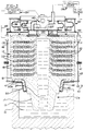
- Figure 1 is a sectioned, side elevational view of a vacuum-assisted, countergravity casting apparatus in accordance with the invention.
- Figure 2 is a fragmentary cross-sectional view of the casting mold taken along lines 2-2 of Fig. 1.
- Figure 3 is a sectioned, side elevational view similar to Fig. 1 showing the mold filled with the melt after casting.
- Figure 4 is a sectioned, side elevation similar to Fig. 1 showing the melt drained from the mold fill sprue without siphoning the melt from the mold cavities.
- FIGS 1-2 illustrate a vacuum assisted, countergravity casting apparatus in accordance with one embodiment of the invention.
- the apparatus includes a container 10 of melt 12 (e.g., molten metal) to be drawn up in to the gas permeable mold 14.
- the gas permeable mold 14 includes a gas permeable lower mold member 16 having a depending integral fill tube 17 adapted for immersion in the melt 12 and a plurality of gas permeable mold members 18 stacked atop the lower mold member 16 to define a plurality of generally horizontal parting planes P therebetween.
- the fill tube 17 may be integral to the bottom mold member 16 (as shown) or a separate tube attached thereto.
- a plurality of mold cavities 22 are formed at each parting plane P and are communicated to a central, upstanding sprue 24 (defined by the mold members 16,18) via a respective ingate system 26 located at each parting plane P.
- the mold cavities 22 are spaced apart circumferentially about the upstanding fill sprue 26 at each parting plane P.
- the fill sprue 24 includes an open lower end 24a adapted for immersion in the melt 12 and an upper end 24b closed off by the gas permeable topmost mold member 18.
- a plurality of upstanding vacuum access passages 19 extend through the mold members 16,18 and are circumferentially spaced apart about the sprue 24 between the mold cavities 22 to facilitate access of subambient pressure to the mold cavities 22.
- Each ingate system 26 includes a plurality of first ingates 28 connecting the sprue 24 to an ingate annulus 30 and a plurality of second ingates 32 connecting the ingate annulus 30 to a respective mold cavity 22.
- the first ingates 28 of each system 26 descend from the sprue 24 toward the mold cavities 22 proximate thereto for purposes to be explained hereinbelow.
- the mold members 16,18 can be made of resin-bonded sand in accordance with known mold practice wherein a mixture of sand and bonding material is formed to shape and cured or hardened against a contoured metal pattern (not shown) having the desired complementary contour or profile for the parting planes P; i.e., the mold cavities 22 and the ingate systems 26.
- the bonding material is usually present in minor percentage, such as less than about 5% by weight of the mixture.
- the resin-bonded, self-supporting sand mold members 16,18 may optionally be adhesively secured together at the parting planes P.
- the invention is advantageously used with the stacked, resin-bonded sand mold members 16,18 shown in Figure 1, the invention is not so limited and may be used with other mold types such as one piece or multi-piece high temperature bonded ceramic molds; e.g., as shown in U.S. Patent 4,112,997.
- the gas permeable mold 14 is shown sealingly received in a vacuum box 40 having a bottom portion 40a and a top portion 40b releasably sealed together at an annular resilient (rubber) seal 41.
- the bottom portion 40b includes an annular bottom support wall 42 and a peripheral side wall 43.
- the lower mold member 16 is sealingly supported on the support wall 42 via a heat resistant metal annular support collar 46 and an annular, refractory gasket 47.
- the collar 46 includes an annular, flat support surface 46a on which the mold members 16,18 are stacked such that they mate tightly together at the parting planes P.
- the collar 46 is sealed to the lower mold member 16 by an annular refractory gasket 45 and, as mentioned, is sealed to the bottom support wall 42 via the annular refractory gasket 47.
- the collar 46 is thermally protected from the heat of the melt 12 by an annular metal shield 50 fastened to the support wall 42 by a plurality of circumferentially spaced apart bolts (not shown).
- the shield 50 forms a thermally insulating air space 50a between the collar 46 and the shield 50 to this end.
- the top portion 40b of the vacuum box 40 includes a peripheral wall 48 and a ceiling structure 49 overlying the top 14a of the mold 14.
- the ceiling structure comprises a horizontal plate 60 affixed as by welding to the peripheral wall 48 and an annular plate assembly 62 fastened on the plate 60 and sealed thereto via an annular resilient (rubber) seal 64.
- Plate assembly 62 includes an upper plate 62a and a side plate 62b that joins the upper plate 62a to the plate 60.
- the plate assembly 62 includes an opening 70 in upper plate 62a to accommodate a chamber-forming structure 80 and a mold-biasing structure 82 that are movable relative to the plate 60 and plate assembly 62.
- the mold-biasing structure 82 comprises a tubular body 84 suspended from the plate assembly 62 to overlie a peripheral portion of the mold top 14a.
- the body 84 is suspended from the plate assembly 62 by an annular flexible sleeve or wall 86 fastened therebetween.
- the sleeve 86 is fastened over raised elongated shoulders 88,90 disposed on the plate assembly 62 and the tubular body 84, respectively, for purposes to be explained below.
- a plurality of circumferentially, spaced apart pins 93 are fastened (e.g., screwed) to the underside of the tubular body 84 and include enlarged lower heads 93a for bearing on a metal (e.g., steel) bearing plate 51 disposed atop the mold 14.
- the mold-biasing structure 82 functions to bias the mold toward the vacuum box bottom support wall 42, thereby biasing members 16,18 together at the generally horizontal parting planes P.
- the chamber-forming structure 80 overlies a central portion of the mold top 14a above the sprue 24.
- the chamber-forming structure 80 is suspended from an inwardly extending flange 94 of the tubular body 84 by an annular flexible sleeve or wall 96.
- the sleeve 96 is affixed to the flange 94 and to a horizontal plate 100 of the structure 80 so as to overlie raised elongated shoulders 102,104 thereon, respectively, for purposes to be explained below.
- An annular passage 110 is formed beneath the plate 100 by concentric, annular side panels 112,114 and bottom plate 116, Figure 1.
- the side panel 112 includes a plurality of circumferentially spaced apertures 118 (two shown) that communicate the passage 110 to a first central chamber 120 surrounded thereby.
- the first chamber 120 is disposed above the mold top 14a over the sprue 24 and is separated from the sprue 24 by the gas permeable (porous) wall 18a of the topmost mold member 18.
- An annular resilient (rubber) seal 124 is carried on the bottom plate 116 and sealingly engages the mold top 14a as shown to sealingly isolate the first chamber 120 from a second chamber 130 formed about the mold periphery 14b by the vacuum box 40.
- the first chamber 120 is communicated by a commercially available pilot operated, or direct solenoid operated, valve means 140 to a source 134 of subambient pressure (e.g., a vacuum pump) or, alternately, to a pressure source 136 as shown in Figure 1 via conduits 142,143,145.
- the pressure source 136 may simply comprise ambient (i.e., atmospheric) pressure exterior of the vacuum box 40.
- the source 136 may comprise a conventional source of compressed gas maintained at a preselected pressure, for example, a pressure of 5 psi.
- the compressed gas may comprise air, a gas that is non-reactive with the melt 12 (e.g., an inert gas such as argon) or other gas suitable for use with the melt 12 being cast.
- valve means 140 When the first chamber 120 is communicated to the subambient pressure source 134 via the valve means 140, subambient pressure will be applied to the first chamber 120 and to the mold fill sprue 24 through the gas permeable (porous) wall 18a of the topmost mold member 18. Alternately, when the first chamber 120 is communicated to the pressure source 136, increased pressure will be applied to the mold fill sprue 24 through the gas permeable wall 18a.
- the valve means 140 is thus operable to connect the first chamber 120 to either the vacuum source 134 or the pressure source 136.
- the second chamber 130 is communicated to the source of subambient pressure by conduits 146 (shown schematically) extending from fittings 148 on the vacuum box wall 48. Those skilled in the art will appreciate that the second chamber 130 may be communicated to the same or different vacuum source 134 as the first chamber 120.
- the vacuum box 40 is initially in the open condition (i.e., the top portion 40b is separated from the bottom portion 40a).
- the mold 14 and the support collar 46 are first positioned on the vacuum box bottom wall 42 with the collar 46 sealingly engaged against the gasket 47 and with the fill tube 17 extending downwardly outside the vacuum box 40.
- the top portion 40b of the vacuum box 40 is sealably secured by suitable clamps (not shown) on the bottom portion 40a (i.e., at seal 41) as shown in Figure 1.
- the pins 93 of the mold-biasing structure 82 are placed in bearing relation on the bearing plate 51 and the seal 124 of the chamber-forming structure 80 contacts the mold top 14a as shown in Figure 1.
- the assembled vacuum box 40 with the mold 14 therein is positioned above the melt 12 and then lowered toward the melt 12 to immerse the open lower end 24a of the fill sprue 24 in the melt 12 as shown in Figure 1.
- the vacuum box 40 is lowered (and raised), for example, by a hydraulic arm mechanism (not shown) of the type illustrated in U.S. Patent 4,340,108.
- the first chamber 120 and the second chamber 130 are then evacuated by communication to the source 134.
- the first chamber 120 is communicated to the source 134 by appropriate operation of the valve means 140.
- Evacuation of the first chamber 120 applies subambient pressure to the sprue 24 through the gas permeable mold top 14a (i.e., wall 18a) while evacuation of the second chamber 130 applies subambient pressure to the mold cavities 22 through the mold periphery 14b.
- Evacuation of the second chamber 130 establishes a negative differential pressure across the sleeves 86,96 of the mold-biasing structure 82 and the chamber-forming structure 80 (i.e., between the sleeve outer sides which are exposed to ambient or atmospheric pressure and the sleeve inner sides which are communicated to the evacuated chamber 130 via apertures 132 in plate 60).
- This negative differential pressure causes the sleeves 86,96 to be pressed on the shoulders 88,90 and 102,104, respectively, such that the chamber-forming structure 80 and the mold-biasing structure 82 are biased toward the mold 14 to tightly engage the pins 93 against the bearing plate 51 and the seal 124 sealingly against the mold top 14a.
- This presses the several mold members 18 tightly together at the generally horizontal mold parting planes P so as to eliminate the need to glue the several members together.
- the subambient pressure applied to the chambers 120,130 (by the source 134) and thus to the sprue 24 and the mold cavities 22 is sufficient to urge the melt 12 upwardly from the container 10 to fill the sprue 24 and the mold cavities 22 via the ingate systems 26 as shown in Figure 3.
- the melt 12 can be drawn upwardly to fill the sprue 24 and the mold cavities 22 via the ingates 26 by evacuating only the second chamber 130 (i.e., it is possible to countergravity cast the melt 12 into the mold cavities 12 without evacuating the first chamber 120).
- sufficient subambient pressure is applied to the mold fill sprue 24 and the mold cavities 22 by evacuation of the second chamber 130 alone to urge the melt upwardly into the fill sprue 24 and the mold cavities 22 via the ingate systems 26.
- the valve means 140 is actuated to close off the first chamber 120 from the subambient pressure source 134 and the pressure source 136.
- the valve means 140 is actuated to communicate the first chamber 120 to the pressure source 136 while the second chamber 130 remains evacuated by the vacuum source 134.
- the pressure applied to the first chamber 120 and thus to the sprue 24 is selectively raised relative to the subambient pressure applied to the mold cavities 22.
- the positive differential pressure established by communicating the first chamber 120 to the pressure source 136 is sufficient to cause the melt 12 in the sprue 24 to drain downwardly out of the sprue lower open end 24a for return to the container 10 without siphoning the melt 12 in the mold cavities 22 therefrom ( Figure 4).
- the sprue 24 can be drained of melt 12 without adversely affecting the soundness of the castings formed in the mold cavities 22.
- the vacuum box 40 and the mold 14 (having melt-filled mold cavities 22) is raised to withdraw the fill tube 17 out of the melt 12.
- the vacuum box 40 and the mold 14 are then transported to a demold station (not shown) where the vacuum box 40 and the mold 14 are separated.
- the vacuum box 40 can then be reused to cast another mold 14 as described hereinabove.
- the mold 14 can be disassembled to remove the solidified castings therefrom.
- pressurized gas may be introduced into the first chamber 120 by actuating the valve means 140 to communicate the chamber 120 to the pressure source 136 which, as mentioned above, may comprise a conventional source of compressed gas such as, for example, air or inert gas.
- the pressurized gas introduced into the sprue 24 is discharged from the sprue lower open end 26a toward the surface region 12a of the melt 12 where the open lower end 24a will be immersed.
- the discharged gas impinges on the melt surface region 12a as the sprue open lower end 24a is immersed in the melt 12 so as to blow any slag, inclusions and other floating debris away from the surface region 12a, thereby reducing the amount of debris entering the mold 14 and ultimately the mold cavities 22 when the melt 12 is drawn upwardly thereinto during casting.
Landscapes
- Engineering & Computer Science (AREA)
- Mechanical Engineering (AREA)
- Molds, Cores, And Manufacturing Methods Thereof (AREA)
- Moulds For Moulding Plastics Or The Like (AREA)
- Casting Support Devices, Ladles, And Melt Control Thereby (AREA)
Applications Claiming Priority (2)
| Application Number | Priority Date | Filing Date | Title |
|---|---|---|---|
| US07/566,523 US5044420A (en) | 1990-08-13 | 1990-08-13 | Vacuum-assisted, countergravity casting apparatus and method |
| US566523 | 1995-12-04 |
Publications (2)
| Publication Number | Publication Date |
|---|---|
| EP0471285A2 true EP0471285A2 (de) | 1992-02-19 |
| EP0471285A3 EP0471285A3 (en) | 1993-07-28 |
Family
ID=24263256
Family Applications (1)
| Application Number | Title | Priority Date | Filing Date |
|---|---|---|---|
| EP19910113294 Withdrawn EP0471285A3 (en) | 1990-08-13 | 1991-08-08 | Vacuum-assisted, countergravity casting apparatus and method |
Country Status (5)
| Country | Link |
|---|---|
| US (1) | US5044420A (de) |
| EP (1) | EP0471285A3 (de) |
| JP (1) | JPH04231162A (de) |
| BR (1) | BR9103443A (de) |
| CA (1) | CA2047545A1 (de) |
Cited By (2)
| Publication number | Priority date | Publication date | Assignee | Title |
|---|---|---|---|---|
| EP0562170A1 (de) * | 1992-03-26 | 1993-09-29 | General Motors Corporation | Differentialdruck-Gegenschwerkraftgiessen |
| CN110548857A (zh) * | 2019-09-24 | 2019-12-10 | 天锜精密机械(昆山)有限公司 | 一种速成真空上吸铸造模 |
Families Citing this family (7)
| Publication number | Priority date | Publication date | Assignee | Title |
|---|---|---|---|---|
| JP3794033B2 (ja) * | 1995-02-07 | 2006-07-05 | 日立金属株式会社 | 減圧吸引鋳造方法及びその装置 |
| US6453976B1 (en) * | 1999-10-29 | 2002-09-24 | Hitchiner Manufacturing Co., Inc. | Lost foam countergravity casting |
| JP2008531289A (ja) | 2005-02-22 | 2008-08-14 | ミルウォーキー・スクール・オブ・エンジニアリング | 鋳造プロセス |
| WO2012092244A2 (en) | 2010-12-29 | 2012-07-05 | Android Industries Llc | Working tank with vacuum assist |
| US9802247B1 (en) * | 2013-02-15 | 2017-10-31 | Materion Corporation | Systems and methods for counter gravity casting for bulk amorphous alloys |
| CN109014134A (zh) * | 2017-06-12 | 2018-12-18 | 科华控股股份有限公司 | 一种耐热钢涡壳壳型叠箱真空吸铸工艺方法 |
| CN108941513A (zh) * | 2018-09-26 | 2018-12-07 | 成都艾特安科技有限公司 | 金属液压力输送壳型铸造方法 |
Family Cites Families (14)
| Publication number | Priority date | Publication date | Assignee | Title |
|---|---|---|---|---|
| US2379401A (en) * | 1942-04-16 | 1945-06-26 | American Steel Foundries | Method and apparatus for casting metal |
| US3900064A (en) * | 1972-12-04 | 1975-08-19 | Hitchiner Manufacturing Co | Metal casting |
| US3863706A (en) * | 1972-12-04 | 1975-02-04 | Hitchiner Manufacturing Co | Metal casting |
| US4112997A (en) * | 1977-02-28 | 1978-09-12 | Hitchiner Manufacturing Co., Inc. | Metal casting |
| US4606396A (en) * | 1978-10-02 | 1986-08-19 | Hitchiner Manufacturing Co., Inc. | Sand mold and apparatus for reduced pressure casting |
| US4340108A (en) * | 1979-09-12 | 1982-07-20 | Hitchiner Manufacturing Co., Inc. | Method of casting metal in sand mold using reduced pressure |
| SU996089A1 (ru) * | 1981-07-28 | 1983-02-15 | Горьковский Ордена Трудового Красного Знамени Политехнический Институт Им.А.А.Жданова | Способ лить вакуумным всасыванием в керамическую газопроницаемую форму и устройство дл его осуществлени |
| SU1215841A1 (ru) * | 1983-06-17 | 1986-03-07 | Волгоградский инженерно-строительный институт | Способ лить по выплавл емым модел м |
| IN170880B (de) * | 1987-05-07 | 1992-06-06 | Metal Casting Tech | |
| US4791977A (en) * | 1987-05-07 | 1988-12-20 | Metal Casting Technology, Inc. | Countergravity metal casting apparatus and process |
| US4858672A (en) * | 1988-05-25 | 1989-08-22 | General Motors Corporation | Countergravity casting apparatus and method |
| US4828011A (en) * | 1988-06-24 | 1989-05-09 | General Motors Corporation | Countergravity casting apparatus |
| US4809767A (en) * | 1988-06-24 | 1989-03-07 | General Motors Corporation | Countergravity casting apparatus |
| US4862945A (en) * | 1988-08-30 | 1989-09-05 | General Motors Corporation | Vacuum countergravity casting apparatus and method with backflow valve |
-
1990
- 1990-08-13 US US07/566,523 patent/US5044420A/en not_active Expired - Fee Related
-
1991
- 1991-07-22 CA CA002047545A patent/CA2047545A1/en not_active Abandoned
- 1991-08-08 EP EP19910113294 patent/EP0471285A3/en not_active Withdrawn
- 1991-08-12 JP JP3225273A patent/JPH04231162A/ja active Pending
- 1991-08-12 BR BR919103443A patent/BR9103443A/pt not_active Application Discontinuation
Cited By (2)
| Publication number | Priority date | Publication date | Assignee | Title |
|---|---|---|---|---|
| EP0562170A1 (de) * | 1992-03-26 | 1993-09-29 | General Motors Corporation | Differentialdruck-Gegenschwerkraftgiessen |
| CN110548857A (zh) * | 2019-09-24 | 2019-12-10 | 天锜精密机械(昆山)有限公司 | 一种速成真空上吸铸造模 |
Also Published As
| Publication number | Publication date |
|---|---|
| JPH04231162A (ja) | 1992-08-20 |
| CA2047545A1 (en) | 1992-02-14 |
| BR9103443A (pt) | 1992-05-12 |
| US5044420A (en) | 1991-09-03 |
| EP0471285A3 (en) | 1993-07-28 |
Similar Documents
| Publication | Publication Date | Title |
|---|---|---|
| US3863706A (en) | Metal casting | |
| US3900064A (en) | Metal casting | |
| US2379401A (en) | Method and apparatus for casting metal | |
| US4993473A (en) | Differential pressure, countergravity casting using mold ingate chills | |
| US5044420A (en) | Vacuum-assisted, countergravity casting apparatus and method | |
| US4862945A (en) | Vacuum countergravity casting apparatus and method with backflow valve | |
| CN1040529A (zh) | 反重力铸造方法及其设备 | |
| US4957153A (en) | Countergravity casting apparatus and method | |
| US3705615A (en) | Metal casting processes with vacuum and pressure | |
| US4971131A (en) | Countergravity casting using particulate filled vacuum chambers | |
| US4858672A (en) | Countergravity casting apparatus and method | |
| JPH04231144A (ja) | 金属の低圧鋳造のための方法、鋳型及び設備 | |
| US5062466A (en) | Countergravity casting apparatus and method | |
| EP0562170B1 (de) | Differentialdruck-Gegenschwerkraftgiessen | |
| US4865113A (en) | Countergravity casting apparatus and process for casting thin-walled parts | |
| EP1082187B1 (de) | Feingiessen unter verwendung einer abdichtbaren druckkappe | |
| US5174356A (en) | Casting apparatus | |
| US5062467A (en) | Vacuum countergravity casting apparatus and method | |
| JPH06182520A (ja) | 吸引鋳造装置 | |
| JPH0756112Y2 (ja) | 真空脱ガス低圧鋳造装置 | |
| US5035277A (en) | Counter gravity casting apparatus | |
| JPS5884662A (ja) | 加圧鋳造法及び装置 | |
| JPH0741400B2 (ja) | 生型鋳造における吸引鋳造方法 | |
| JPH0571332B2 (de) | ||
| JPH05161953A (ja) | 鋳造装置 |
Legal Events
| Date | Code | Title | Description |
|---|---|---|---|
| PUAI | Public reference made under article 153(3) epc to a published international application that has entered the european phase |
Free format text: ORIGINAL CODE: 0009012 |
|
| AK | Designated contracting states |
Kind code of ref document: A2 Designated state(s): DE FR GB IT |
|
| PUAL | Search report despatched |
Free format text: ORIGINAL CODE: 0009013 |
|
| AK | Designated contracting states |
Kind code of ref document: A3 Designated state(s): DE FR GB IT |
|
| 17P | Request for examination filed |
Effective date: 19940127 |
|
| STAA | Information on the status of an ep patent application or granted ep patent |
Free format text: STATUS: THE APPLICATION HAS BEEN WITHDRAWN |
|
| 18W | Application withdrawn |
Withdrawal date: 19940416 |