EP0471300A2 - Machine automatique de guichet - Google Patents
Machine automatique de guichet Download PDFInfo
- Publication number
- EP0471300A2 EP0471300A2 EP91113349A EP91113349A EP0471300A2 EP 0471300 A2 EP0471300 A2 EP 0471300A2 EP 91113349 A EP91113349 A EP 91113349A EP 91113349 A EP91113349 A EP 91113349A EP 0471300 A2 EP0471300 A2 EP 0471300A2
- Authority
- EP
- European Patent Office
- Prior art keywords
- bill
- bills
- receiving
- rotary body
- customer
- Prior art date
- Legal status (The legal status is an assumption and is not a legal conclusion. Google has not performed a legal analysis and makes no representation as to the accuracy of the status listed.)
- Granted
Links
Images



Classifications
-
- G—PHYSICS
- G07—CHECKING-DEVICES
- G07F—COIN-FREED OR LIKE APPARATUS
- G07F19/00—Complete banking systems; Coded card-freed arrangements adapted for dispensing or receiving monies or the like and posting such transactions to existing accounts, e.g. automatic teller machines
- G07F19/20—Automatic teller machines [ATMs]
-
- G—PHYSICS
- G07—CHECKING-DEVICES
- G07D—HANDLING OF COINS OR VALUABLE PAPERS, e.g. TESTING, SORTING BY DENOMINATIONS, COUNTING, DISPENSING, CHANGING OR DEPOSITING
- G07D11/00—Devices accepting coins; Devices accepting, dispensing, sorting or counting valuable papers
- G07D11/10—Mechanical details
- G07D11/14—Inlet or outlet ports
-
- G—PHYSICS
- G07—CHECKING-DEVICES
- G07F—COIN-FREED OR LIKE APPARATUS
- G07F19/00—Complete banking systems; Coded card-freed arrangements adapted for dispensing or receiving monies or the like and posting such transactions to existing accounts, e.g. automatic teller machines
- G07F19/20—Automatic teller machines [ATMs]
- G07F19/205—Housing aspects of ATMs
Definitions
- a variety of automatic teller machines have heretofore been developed and actually employed to permit the automatic depositing or dispensing of bills when operated by a customer. They include, for example, those equipped with the bill receiving/dispensing unit disclosed in Japanese Patent Application Laid-Open (Kokai) No. SHO 60-251487.
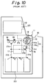
- FIG. 10 is a simplified, schematic side view showing the internal construction of the conventional automatic teller machine, in which the money-receiving/dispensing unit designated generally at numeral 11 is provided with a shutter 12, a rotary body 13, a bill guide 14 and an inserter frame 15.
- the receiving/dispensing unit 11 has a roller for introducing bills into the bill guide 14, feeding out the bills from the bill guide 14 and holding the bills inside the bill guide 14.
- a customer presses an unillustrated deposit transaction button provided in a front customer panel of the machine, and inserts a passbook in an unillustrated passbook insertion slot or a card 23 into an insertion slot 22.
- the machine then conducts communication with a computer center and, when verified, the shutter 12 is opened.
- the rotary body 13 is next rotated by an unillustrated drive source so that the bill guide 14 undergoes an angular displacement to the feed-in position b .
- the bills are then fed out at a low speed in a stacked state by an unillustrated roller from the bill guides 14 to the bill separating and counting unit 16.
- the bills After the bills have been separated and counted one by one at the bill separating and counting unit 16, they are conveyed to a bill discriminator 17 along a transfer path 21a. Bills which have been found "good” as a result of checking by the bill discriminator 17 are conveyed to the first storage portion 18 for storage, while those found "bad” by the bill discriminator 17 are conveyed to the second storage portion 19 for storage.
- the bill guide 14 of the receiving/dispensing unit 11 has undergone an angular displacement to the receiving position c so that the bill guide 14 is ready to receive the bills from the first storage portion 18 or from the second storage portion 19.
- the rotary body 13 then rotates so that the bill guide 14 undergoes an angular displacement to the feedin position b again.
- the bills are fed out to the bill separating and counting unit 16. They are fed further to the bill discriminator 17, so that they are checked again there.
- the shutter 12 is closed and the bill guide 14 returns to the receiving position c .
- the amount dispensed is verified by the customer.
- the bill stored in the first storage portion 18, namely, the bills which have been found "good” are conveyed along the transfer path 21c and are received in the bill guide 14. These bills are then conveyed along a transfer path 21d by way of the bill separating and counting unit 16 and the bill discriminator 17.
- the bills are sorted according to whether they are normal or marred and also according to value denomination, and are then stored in a bill storage box 20 by an unillustrated storing means.
- the customer presses an unillustrated withdrawal button provided in the customer panel. After insertion of the card 23 into the card insertion slot 22, the customer presses appropriate personal code number buttons and withdrawal amount buttons, causing the machine to communicate with the computer center.
- the necessary number of bills is dispensed by a paying-out means according to value denomination from the bill storage box 20 and are fed out to a transfer path 21e.
- the bills are fed out from the transfer path 21e to the transfer path 21a and are then conveyed to the bill discriminator 17.
- Checking is conducted by the bill discriminator 17.
- Bills confirmed as "good” by the bill discriminator 17 are conveyed along the transfer path 21b and are then stored in the first storage portion 18.
- the bills and transaction printout which have been stored in the first storage portion as described above, are conveyed along the transfer path 21c and are then received in the bill guide 14 which has been held in readiness at the receiving position c .
- the rotary body 13 then rotates so that the bill guide 14 undergoes an angular displacement to the customer position a .
- the shutter 12 is opened and the bills are thus dispensed to the customer.
- the rotary body 13 rotates so that the bill guide 14 undergoes an angular displacement to a feed-in position d and the bills and transaction printout are fed out to and stored in the temporary storage box 24.
- the transfer of bills from the receiving/dispensing unit to the separating unit requires thee bills to be stacked so that there is a high possibility of causing a transfer problem such as jamming during transfer of the bills. This results in a reduction in the reliability of the transfer and, since the transfer of the bills from the receiving/dispensing unit to the separating unit is carried out at a low speed, also in the problem that the processing speed of bills is slow.
- a first object of the present invention is to provide an automatic teller machine equipped with a receiving/dispensing unit which permits simplification and size reduction of the machine, enhances the reliability of conveyance and further improves the processing speed of bills.
- the present invention also provides an automatic teller machine with a receiving/dispensing unit in a customer panel of a main body of the machine.
- the receiving/dispensing unit has a rotary body, which is composed of two flanges supported for rotation in an opposing relationship and two plate-like bill guides fixed in an opposing relationship and extending in a direction perpendicular to the flanges, and an openable shutter arranged to cover the rotary body at a position facing a customer, whereby the rotary body with bills received together therein is rotated and then stopped at a receiving/dispensing dispensing position to conduct a receiving/dispensing procedure.
- One ends of the bill guides serve as a receiving opening for receiving the bills from the customer panel.
- a gear is formed in an outer periphery of at least one of the flanges.
- the rotary body is provided with a means for separating and feeding the bills one by one and an opening for feeding the thus-separated bills into the main body.
- a drive source is also provided to rotate the gear.
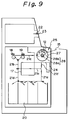
- FIG. 9 there are shown a bill discriminator 17, a first storage portion 18, a second storage portion 19, a bill storage box 20, transfer paths 21a-21f constructed of bill conveying means, a card insertion slot 22, a passbook or card 23, and a temporary storage box 24.
- They are the same elements as the corresponding elements in the conventional automatic teller machine and are thus identified by the same symbols.
- a receiving/dispensing unit 25 has the functions of both the conventional receiving/dispensing unit 11 and the separating and counting unit 16.
- the drawing shows only a shutter 12, a rotary body 27, a bill guide 28 and an inserter frame 15 out of various elements making up the receiving/dispensing unit 25.
- the rotary body 27 and the transfer path 21a are connected by way of a transfer path 21f.
- the receiving/dispensing unit 25 in the automatic teller machine has a rotary body 27 supported for free rotation on short shafts 34,35 which are in tern supported by bearings 32,33 mounted on side frames 30,31 indicated by two-dot chain lines and arranged in a pair.
- a motor 39 as a drive source for the rotary body is a motor for rotating the rotary body 27, and a motor gear 41 is provided on a motor shaft.
- a flange 36 with a gear 40 formed therein is mounted on the short shaft 34, whereby rotation of the motor 39 can turn the rotary body 27.
- a slit disk 42 is also fixed on the short shaft 34 of the flange 36. Reading of the degree of rotation of the slit disk 42 by an encoder 43 makes it possible to detect the angle of rotation of the rotary body 27. To cause the rotary body 27 to rotate to a predetermined position, the motor 39 is controlled while detecting the position of the rotary body 27 by means of the encoder 43.
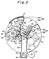
- the rotary body 27 is provided with two flanges 36,37 fixed in an opposing relationship on the short shafts 34,35, two bill guides 28a,28b and two coin guides 44a,44b, both arranged in directions perpendicular to the flanges 36,37 so that they extend between the flange 36 and the flange 37 as shown in FIG.
- a bill pusher 46 arranged on a side of the bill guide 28b movably toward and away relative to a center guide 45, a feed roller 48 fixed on a shaft 47 so that the feed roller 48 is located at an inner end of the bill guide 28a, a reverse roller 50 fixed on a shaft 49 so that the reverse roller 50 contacts the feed roller 48, and a picker roller 52 fixed on a shaft 51 so that a part of an outer periphery of the picker roller 52 enters toward the bill pusher 46 through an opening formed in the center guide 45 as depicted in FIG. 1.
- the center guide 45 has tabs 53a,53b at opposite ends thereof and, as is shown in FIG.
- the center guide 45 is caused to pivot in the direction of arrow A and is brought into contact with a stopper 54.
- the bill pusher 46 has been formed by fixing square U-shaped brackets 59,60 by welding or the like so that both arm portions 61,62 extend in opposite directions.
- the arm portions 61 of the bracket 59 extend out through rectangular slots 63 formed in the flanges 36,37, respectively, and hook portions 64 at free ends of the arm portions 61 are maintained in engagement with the spring posts 56 provided on the center guide 45.
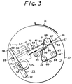
- the hook portions 64 defines spring holes 65 respectively as illustrated in FIG. 3.
- springs 67 extend between the spring holes 65 and corresponding spring posts 66 formed on the flanges 36,37.
- guide posts 68,69 are provided on each of the arm portions 62 of the bracket 60 as shown in FIGS. 1-3. The guide posts 68,69 are allowed to slide in the direction of arrows C,D along a slot 70 formed in each of the flanges 36,37.
- a motor 71 as a drive source for the bill pusher is fixedly secured on the flange 37 as shown in FIGS. 1 and 2.
- a bracket 72 with a pin 73 fixed thereon is mounted on a motor shaft of the motor 71.
- the pin 73 extends out through a circular guide slot 74 formed in the flange 37 and is maintained in engagement with a slot 76 formed in a link 75.
- the link 75 pivots in the directions of arrows E,F about a post 77 provided on the flange 37.
- the link 75 is detected by sensors 78,79, whose detection signals control the motor 71.
- front end portions of the bill guides 28a,28b define the receiving opening 26 through which stacked bills 80 can be inserted or taken out.
- the opening 26 flares out.
- the shaft 47 of the feed roller 48, the shaft 49 of the reverse roller 50 and the shaft 51 of the picker roller 52 are all supported for rotation at opposite ends thereof on the flanges 36,37.
- a gear 81 is provided on one end of the shaft 47 of the feed roller 48.
- the gear 81 is maintained in meshing engagement with a screw gear 83 of a motor 82 provided as a drive source for the rollers on an outer wall of the flange 36.
- pulleys 84,85,86 are provided on the other ends of the shafts 47,49,51 of the feed, reverse and picker roller 48,50,52, respectively.
- a belt 87 is fitted on the individual pulleys 84-86.
- Drive force of the motor 82 is therefore transmitted to the shaft 47 via the screw gear 83 and the gear 81 and further from the shaft 47 to the shafts 49,51 by way of the pulley 84, the belt 87 and the pulleys 85,86, whereby the feed roller 48, reverse roller 50 and picker rollers 52 are rotated, respectively.
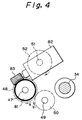
- the individual rollers 48,50,52 all rotate clockwise as shown in FIG. 4.
- the direction of rotation of the reverse roller 50 kept in contact with the feed roller 48 is however opposite to the direction of rotation of the feed roller 48, said direction being indicated by arrow a at the point of contact between both the rollers.
- the feed roller 48, reverse roller 50 and picker roller 52 rotate in the state that the bills 80 are pushed against the picker roller 52 by means of the bill pusher 46, the first bill 80 which is in contact with the picker roller 52 is fed to the point of contact between the feed roller 48 and the reverse roller 50 and is fed further by further rotation of the feed roller 48, so that the bill 80 is fed in from the rotary body 27. If the second bill 80 is in close contact with the first bill 80 at this time, the second bill 80 sticking close to the first bill 80 is separated by the reverse roller 50 which rotates in the opposite direction to the feed roller 48. The bills 80 can therefore be separated and fed in one by one.
- Each separated bill 80 is conveyed along a transfer path 88 through a feed-in opening into the machine.
- sensors 89,90,91 are provided respectively, so that the presence or absence of the bill 80 is detected.
- These sensors are composed of light emitting devices 89a,90a,91a and photodetectors 89b,90b,91b, respectively.
- an under guide 92 as shown in FIG. 5 is provided on the top of the coin guides 44a,44b. 5 is provided. Through openings 93, coils 94 and other foreign objects held between the bills 80 are caused to drop into a catch tray 95.
- FIG. 6 To a central processing unit 100 (hereinafter referred to as "CPU 100"), a main storage device 101 (hereinafter referred to as “memory 101”) and an interface 102 are connected via bus lines 103,104, respectively.
- the motors 39,71, 82, encoder 43 and sensors 78,79,89,90,91 are connected to the interface 102 via lines 105-113, respectively.
- a control program, position data for the rotary body 27, etc. are stored in the memory 101.
- step S1 a customer presses an unillustrated deposit transaction button provided in a customer panel of the machine.
- the card 23 is inserted into the card insertion slot 22 as shown in FIG. 9, communication with a computer center is carried out.
- CPU 100 actuates the motor 39 in step S2 so that the rotary body 27 is rotated via the gear 41 and flange 36.
- CPU 100 then reads the degree of rotation of the rotary body 27 by means of the encoder 43 and compares it with the position data stored in the memory 101.
- the receiving opening 26 of the bill guide 28 moves to the customer position a , the motor 39 is stopped so that the rotary body 27 is held in readiness.
- CPU 100 detects via the sensor 78 that the bill pusher 46 is fully open.
- step S3 CPU 100 actuates an unillustrated motor to open the shutter 12.
- CPU 100 detects the insertion of the bills 80 via the sensors 89,90. If the coins 94 and other foreign objects are contained between the bills 80 at this time, they are caused to drop into the catch tray 95 through the openings 93 of the under guide 92.
- CPU 100 detects the insertion of the bills 80 via the sensors 89,90, CPU 100 closes the shutter 12 in step S5.
- CPU 100 then actuates the motor 71 in step S6, whereby the link 75 is caused to pivot in the direction of arrow F as shown in FIG. 3. This pivotal movement of the link 75 in the direction of arrow F allows the bill pusher 46 to move in the direction of arrow C under the pulling force of the spring 67.
- the center guide 45 is caused to pivot in the direction of arrow A by the spring 58 as shown in FIG. 2.
- the center guide 45 is brought into contact with the stopper 54 and extends in parallel with the bill pusher 46, the bills 80 are brought into the state that they are held between the picker roller 52 and the bill pusher 46.
- CPU 100 is ready to detect the link 75 via the sensor 79. As soon as the link 75 is detected, CPU 100 stops the actuation of the motor 71 (this state will hereinafter be referred to as the "closure of the bill pusher 46").
- step S7 CPU 100 actuates the motor 39 to rotate the rotary body 27, whereby the receiving opening 26 of the bill guide 28 is positioned at the feedin position b .
- the routine then advances to step S8, where CPU 100 actuates the motor 82 so that the feed roller 48, reverse roller 50 and picker roller 52 are rotated to separate the bills 80 one by one.
- the bills 80 are then fed to the transfer path 21f so that the bills 80 are conveyed into the machine along the transfer path 88.
- CPU 100 monitors the number of the bills 80 and the intervals between the successive bills by means of the sensor 91.
- CPU 100 detects the presence or absence of the bills 80 between the center guide 45 and the bill pusher 46 via the sensors 89,90 in step S9. Upon detection of the absence of the bills 80, the actuation of the motor 82 is stopped. In step S10, CPU 100 actuates the motor 71 to move the bill pusher 46 in the direction of arrow D as shown in FIG. 2. As he bill pusher 46 moves in the direction of arrow D, the center guide 45 is caused to pivot in the direction of arrow B. Upon detection of the link 75 by the sensor 78, the actuation of the motor 71 is stopped (this state will hereinafter be referred to as "opening of the bill pusher 46"). In this state, the machine is now ready to accept the next transaction.
- step S1 a customer presses an unillustrated withdrawal transaction button provided in the customer panel of the machine.
- the card 23 is inserted into the insertion slot 22 as shown in FIG. 9 and appropriate personal code number buttons and withdrawal amount buttons are then pressed, communication with a computer center is carried out.
- CPU 100 actuates the motor 39 in step S2 so that the rotary body 27 is rotated to position the receiving opening 26 of the bill guide 28 at the receiving position c .
- step S3 by an unillustrated paying-out means, CPU 100 dispenses the desired number of bills according to value denomination from the bill storage box 20 and feeds them out to the transfer path 21e.
- the bills are conveyed from the transfer path 21e to the bill discriminator 17 via the transfer path 21a.
- the bills are checked by the bill discriminator 17. Those found to be "good” by the bill discriminator 17 are conveyed along the transfer path 21b, whereby they are stored in the first storage portion 18.
- CPU 100 causes an unillustrated printer to print the details of the transaction in step S4 so that a transaction printout is conveyed to and placed on the bills stored in the first storage portion 18.
- step S5 CPU 100 conveys along the transfer path 21c the bills and transaction printout which have been stored in the first storage portion 18. They are received in the bill guide 28 held in readiness at the receiving position c .
- step S6 CPU 100 actuates the motor 71 to close the bill pusher 46.
- step S7 CPU 100 actuates the motor 39 to rotate the rotary body 27 so that the receiving opening 26 of the bill guide 28 is positioned at the customer position a .
- step S8 CPU 100 actuates the motor 71 to open the bill pusher 46, whereby the bills and transaction printout are released.
- Step S9 CPU 100 causes an unillustrated timer of CPU to start.
- step S9 CPU 100 actuates an unillustrated motor to open the shutter 12.
- step S11 when the customer receives the bills and transaction printout, CPU 100 closes the shutter 12 and the machine is now ready for the next transaction.
- CPU 100 detects a timeout in step S13 so that the shutter 12 is closed in step S14.
- CPU 100 then actuates the motor 71 in step S15, whereby the bill pusher 46 is closed.
- step S16 CPU 100 actuates the motor 39 to rotate the rotary body 27 so that the receiving opening 26 of the bill guide 28 is positioned at the feed-in position d .
- step S17 the motor 71 is actuated to open the bill pusher 46, whereby the bills and transaction printout are stored in the temporary storage box 24. The machine is now ready for the next transaction.
Landscapes
- Physics & Mathematics (AREA)
- General Physics & Mathematics (AREA)
- Business, Economics & Management (AREA)
- Accounting & Taxation (AREA)
- Finance (AREA)
- Financial Or Insurance-Related Operations Such As Payment And Settlement (AREA)
- Sheets, Magazines, And Separation Thereof (AREA)
Applications Claiming Priority (4)
| Application Number | Priority Date | Filing Date | Title |
|---|---|---|---|
| JP85875/90U | 1990-08-16 | ||
| JP8587590 | 1990-08-16 | ||
| JP2403579A JP2667739B2 (ja) | 1990-08-16 | 1990-12-19 | 紙幣自動入出金装置 |
| JP403579/90 | 1990-12-19 |
Publications (3)
| Publication Number | Publication Date |
|---|---|
| EP0471300A2 true EP0471300A2 (fr) | 1992-02-19 |
| EP0471300A3 EP0471300A3 (en) | 1992-12-23 |
| EP0471300B1 EP0471300B1 (fr) | 1995-11-08 |
Family
ID=26426877
Family Applications (1)
| Application Number | Title | Priority Date | Filing Date |
|---|---|---|---|
| EP91113349A Expired - Lifetime EP0471300B1 (fr) | 1990-08-16 | 1991-08-08 | Machine automatique de guichet |
Country Status (4)
| Country | Link |
|---|---|
| US (1) | US5199697A (fr) |
| EP (1) | EP0471300B1 (fr) |
| JP (1) | JP2667739B2 (fr) |
| DE (1) | DE69114406T2 (fr) |
Cited By (20)
| Publication number | Priority date | Publication date | Assignee | Title |
|---|---|---|---|---|
| EP0582473A3 (fr) * | 1992-08-07 | 1994-02-23 | Ncr Int Inc | |
| EP0793197A3 (fr) * | 1996-02-29 | 1999-03-31 | Laurel Bank Machines Co., Ltd. | Machine de traitement de billets de banque |
| EP0793198A3 (fr) * | 1996-02-29 | 1999-09-01 | Laurel Bank Machines Co., Ltd. | Machine de traitement de billets de banque |
| EP1457940A1 (fr) * | 2003-02-26 | 2004-09-15 | M.I.B. S.p.A. | Dispositif pour la protection d'une ouverture de distribution pour des billets de banque et des objects de valeur |
| EP1422674A4 (fr) * | 2001-08-30 | 2006-04-26 | Fujitsu Ltd | Appareil de transaction automatique de monnaie, et unite de monnaie de papier a camera integree |
| EP1783702A3 (fr) * | 1998-12-08 | 2007-06-27 | Hitachi-Omron Terminal Solutions, Corp. | Machine de dépôt/retrait de billets pour déposer/retirer des billets |
| EP1926057A1 (fr) * | 2006-11-24 | 2008-05-28 | Hitachi-Omron Terminal Solutions, Corp. | Appareil de dépôt/retrait de factures et son procédé de contrôle |
| WO2009083140A1 (fr) * | 2007-12-21 | 2009-07-09 | Giesecke & Devrient Gmbh | Installation de réception et d'émission de billets de banque |
| WO2010046359A1 (fr) * | 2008-10-22 | 2010-04-29 | Wincor Nixdorf International Gmbh | Dispositif et procédé d'individualisation de billets de banque se trouvant dans un empilement de billets de banque |
| DE202005021825U1 (de) | 2004-11-30 | 2010-07-29 | Vogel's Holding B.V. | Vorrichtung, die zum Halten einer Komponente geeignet ist |
| EP1913505A4 (fr) * | 2005-07-01 | 2010-10-06 | Diebold Inc | Gab avec transporteur de piles pour depot de billets de banque en vrac |
| CN102396007A (zh) * | 2009-04-16 | 2012-03-28 | 卡纳安·拉卡斯密纳拉扬 | 用于现金提款机的呈现、缩回和清理机构 |
| CN102682515A (zh) * | 2011-03-09 | 2012-09-19 | 冲电气工业株式会社 | 纸张类处理装置及交易装置 |
| EP2511884A4 (fr) * | 2009-12-31 | 2013-07-17 | Nautilus Hyosung Inc | Équipement d'automatisation financière et procédé de commande |
| CN103544771A (zh) * | 2011-07-15 | 2014-01-29 | 日立欧姆龙金融系统有限公司 | 纸币处理装置 |
| CN104157074A (zh) * | 2014-08-20 | 2014-11-19 | 广州广电运通金融电子股份有限公司 | 旋转式纸币输送装置 |
| EP2747044A4 (fr) * | 2011-08-17 | 2015-02-25 | Grg Banking Equipment Co Ltd | Mécanisme de porte |
| CN104821040A (zh) * | 2015-05-28 | 2015-08-05 | 广州广电运通金融电子股份有限公司 | 一种分钞装置 |
| EP3379503A1 (fr) * | 2017-03-21 | 2018-09-26 | Wincor Nixdorf International GmbH | Dispositif, agencement et procédé d'entrée et/ou de sortie d'un ou de plusieurs documents de valeur |
| EP3561785A1 (fr) * | 2018-04-26 | 2019-10-30 | Capital One Services, LLC | Dispositif de guichet bancaire automatique (atm) à fente étanche |
Families Citing this family (23)
| Publication number | Priority date | Publication date | Assignee | Title |
|---|---|---|---|---|
| US5264765A (en) * | 1992-03-27 | 1993-11-23 | Pecorino Philip A | Video display screen cover |
| US6293469B1 (en) | 1994-12-20 | 2001-09-25 | Dh Technology Inc. | Transaction printer |
| DE19536481A1 (de) * | 1995-09-29 | 1997-04-03 | Siemens Nixdorf Inf Syst | Geldannahme- und -ausgabeautomat |
| US6598023B1 (en) * | 1996-11-27 | 2003-07-22 | Diebold, Incorporated | Automated banking machine system using internet address customer input |
| CN1240551C (zh) * | 1996-11-27 | 2006-02-08 | 英脱布尔特 | 一种自动化银行业务机及其应用方法 |
| JP3451988B2 (ja) * | 1999-07-01 | 2003-09-29 | 株式会社日立製作所 | 紙幣カセット |
| JP3631928B2 (ja) * | 1999-09-30 | 2005-03-23 | 富士通株式会社 | 紙葉類繰り出しユニットおよび紙葉類取り扱い装置 |
| EP1220167A1 (fr) * | 2000-12-28 | 2002-07-03 | Mars Inc. | Entrepôt pour billets de banque |
| US7036650B2 (en) * | 2001-08-07 | 2006-05-02 | De La Rue International Ltd | Sheet accepting apparatus and recycler |
| JP2003085616A (ja) * | 2001-09-11 | 2003-03-20 | Fujitsu Ltd | 紙葉処理装置 |
| JP4012423B2 (ja) * | 2002-03-26 | 2007-11-21 | 日立オムロンターミナルソリューションズ株式会社 | 紙幣取扱装置 |
| KR100608091B1 (ko) * | 2004-07-16 | 2006-08-08 | 엘지엔시스(주) | 매체자동지급기의 스테킹모듈 및 그 제어방법 |
| KR100608078B1 (ko) * | 2004-07-16 | 2006-08-08 | 엘지엔시스(주) | 매체자동지급기 |
| US7350699B2 (en) * | 2005-06-22 | 2008-04-01 | De La Rue International Limited | Financial transactions processing system including cash dispenser or recycler |
| US20080049400A1 (en) * | 2006-08-25 | 2008-02-28 | Philip Pecorino | Cover for a flat panel display |
| KR100799460B1 (ko) * | 2006-12-29 | 2008-02-01 | 노틸러스효성 주식회사 | 지폐입출금장치 |
| US20090063355A1 (en) * | 2007-08-31 | 2009-03-05 | Nizam Antoo | Method and system using reloadable portable consumer devices |
| KR101551490B1 (ko) | 2008-11-25 | 2015-09-08 | 주식회사 엘지씨엔에스 | 밀판 위치검출방법 및 장치, 그리고 그를 이용한 매체출납장치 |
| JP5286060B2 (ja) * | 2008-12-11 | 2013-09-11 | 株式会社東芝 | 紙葉類供給装置 |
| US8567156B2 (en) * | 2009-06-15 | 2013-10-29 | Kabushiki Kaisha Toshiba | Paper sheet processing system |
| US20160371664A1 (en) * | 2015-06-19 | 2016-12-22 | Ncr Corporation | Slotted rotatable drum and method of using same |
| CN105502062B (zh) * | 2016-01-06 | 2017-07-25 | 上海古鳌电子科技股份有限公司 | 一种夹钞、存钞装置 |
| EP3924918B1 (fr) * | 2019-02-12 | 2026-04-01 | ecoATM, LLC | Kiosque pour évaluer et acheter des dispositifs électroniques usagés |
Family Cites Families (11)
| Publication number | Priority date | Publication date | Assignee | Title |
|---|---|---|---|---|
| US3880320A (en) * | 1974-02-25 | 1975-04-29 | Diebold Inc | Rotary cash drawer mechanism for currency dispenser |
| US4744468A (en) * | 1983-11-04 | 1988-05-17 | Laurel Bank Machine Co., Ltd. | Circulation-type bill receiving and dispensing machine |
| JPS60251487A (ja) * | 1984-05-29 | 1985-12-12 | 沖電気工業株式会社 | 入出金口機構 |
| US4866254A (en) * | 1985-08-09 | 1989-09-12 | Hitachi, Ltd. | Automatic bill transaction system |
| KR910008806B1 (ko) * | 1986-06-04 | 1991-10-21 | 가부시키가이샤 히타치세이사쿠쇼 | 거래처리장치 |
| KR880005016A (ko) * | 1986-10-31 | 1988-06-27 | 이께베 이와오 | 지폐출납기의 지폐누름장치 |
| JPS63235234A (ja) * | 1987-03-23 | 1988-09-30 | Toshiba Corp | 紙葉類取込み装置 |
| JPH0721832B2 (ja) * | 1987-11-20 | 1995-03-08 | インタ−ナシヨナル・ビジネス・マシ−ンズ・コ−ポレ−シヨン | 紙幣処理装置 |
| US5020787A (en) * | 1988-05-06 | 1991-06-04 | Laurel Bank Machines Co., Ltd. | Bill processing apparatus |
| JPH0636210B2 (ja) * | 1988-05-06 | 1994-05-11 | ローレルバンクマシン株式会社 | 紙幣処理装置 |
| JPH0688725B2 (ja) * | 1988-05-11 | 1994-11-09 | ローレルバンクマシン株式会社 | 紙幣集積取引装置 |
-
1990
- 1990-12-19 JP JP2403579A patent/JP2667739B2/ja not_active Expired - Lifetime
-
1991
- 1991-07-23 US US07/734,782 patent/US5199697A/en not_active Expired - Fee Related
- 1991-08-08 DE DE69114406T patent/DE69114406T2/de not_active Expired - Fee Related
- 1991-08-08 EP EP91113349A patent/EP0471300B1/fr not_active Expired - Lifetime
Cited By (42)
| Publication number | Priority date | Publication date | Assignee | Title |
|---|---|---|---|---|
| EP0582473A3 (fr) * | 1992-08-07 | 1994-02-23 | Ncr Int Inc | |
| EP0793197A3 (fr) * | 1996-02-29 | 1999-03-31 | Laurel Bank Machines Co., Ltd. | Machine de traitement de billets de banque |
| EP0793198A3 (fr) * | 1996-02-29 | 1999-09-01 | Laurel Bank Machines Co., Ltd. | Machine de traitement de billets de banque |
| US7644914B2 (en) | 1998-12-08 | 2010-01-12 | Hitachi, Ltd. | Bill deposit/withdrawal machine for depositing/withdrawing bills |
| EP1783702A3 (fr) * | 1998-12-08 | 2007-06-27 | Hitachi-Omron Terminal Solutions, Corp. | Machine de dépôt/retrait de billets pour déposer/retirer des billets |
| US7988141B2 (en) | 1998-12-08 | 2011-08-02 | Hitachi-Omron Terminal Solutions, Corp. | Bill deposit/withdrawal machine for depositing/withdrawing bills |
| US7464921B2 (en) | 1998-12-08 | 2008-12-16 | Hitachi, Ltd. | Bill deposit/withdrawal machine for depositing/withdrawing bills |
| EP1422674A4 (fr) * | 2001-08-30 | 2006-04-26 | Fujitsu Ltd | Appareil de transaction automatique de monnaie, et unite de monnaie de papier a camera integree |
| EP1457940A1 (fr) * | 2003-02-26 | 2004-09-15 | M.I.B. S.p.A. | Dispositif pour la protection d'une ouverture de distribution pour des billets de banque et des objects de valeur |
| DE202005021825U1 (de) | 2004-11-30 | 2010-07-29 | Vogel's Holding B.V. | Vorrichtung, die zum Halten einer Komponente geeignet ist |
| EP1913505A4 (fr) * | 2005-07-01 | 2010-10-06 | Diebold Inc | Gab avec transporteur de piles pour depot de billets de banque en vrac |
| EP2116980A1 (fr) * | 2006-11-24 | 2009-11-11 | Hitachi-Omron Terminal Solutions, Corp. | Procédé de contrôle d'un appareil de dépôt/retrait de facture |
| CN101916469B (zh) * | 2006-11-24 | 2014-10-22 | 日立欧姆龙金融系统有限公司 | 纸币出入款装置及纸币出入款装置控制方法 |
| US7708192B2 (en) | 2006-11-24 | 2010-05-04 | Hitachi-Omron Terminal Solutions, Corp. | Bill depositing/withdrawing apparatus and method of controlling the same |
| EP2017799A1 (fr) * | 2006-11-24 | 2009-01-21 | Hitachi-Omron Terminal Solutions, Corp. | Appareil de dépôt/retrait de factures et machine de transaction automatique |
| CN101916469A (zh) * | 2006-11-24 | 2010-12-15 | 日立欧姆龙金融系统有限公司 | 纸币出入款装置及纸币出入款装置控制方法 |
| EP2267668A1 (fr) | 2006-11-24 | 2010-12-29 | Hitachi-Omron Terminal Solutions, Corp. | Appareil de dépôt/retrait de factures et son procédé de contrôle |
| EP2267667A1 (fr) * | 2006-11-24 | 2010-12-29 | Hitachi-Omron Terminal Solutions, Corp. | Appareil de dépôt/retrait de factures et son procédé de contrôle |
| CN101188029B (zh) * | 2006-11-24 | 2011-04-20 | 日立欧姆龙金融系统有限公司 | 纸币出入款装置及纸币出入款装置控制方法 |
| EP1926057A1 (fr) * | 2006-11-24 | 2008-05-28 | Hitachi-Omron Terminal Solutions, Corp. | Appareil de dépôt/retrait de factures et son procédé de contrôle |
| WO2009083140A1 (fr) * | 2007-12-21 | 2009-07-09 | Giesecke & Devrient Gmbh | Installation de réception et d'émission de billets de banque |
| CN102202993B (zh) * | 2008-10-22 | 2017-01-25 | 德利多富信息系统(上海)有限公司 | 用于分离有价票据堆垛的有价票据的装置和方法 |
| WO2010046359A1 (fr) * | 2008-10-22 | 2010-04-29 | Wincor Nixdorf International Gmbh | Dispositif et procédé d'individualisation de billets de banque se trouvant dans un empilement de billets de banque |
| US8205874B2 (en) | 2008-10-22 | 2012-06-26 | Wincor Nixdorf International Gmbh | Device and method for isolating securities of a stack of securities |
| CN102396007A (zh) * | 2009-04-16 | 2012-03-28 | 卡纳安·拉卡斯密纳拉扬 | 用于现金提款机的呈现、缩回和清理机构 |
| EP2511884A4 (fr) * | 2009-12-31 | 2013-07-17 | Nautilus Hyosung Inc | Équipement d'automatisation financière et procédé de commande |
| US8814041B2 (en) | 2009-12-31 | 2014-08-26 | Nautilus Hyosung Inc. | Automatic financial automation equipment and control method thereof |
| CN102682515A (zh) * | 2011-03-09 | 2012-09-19 | 冲电气工业株式会社 | 纸张类处理装置及交易装置 |
| CN103544771B (zh) * | 2011-07-15 | 2015-09-30 | 日立欧姆龙金融系统有限公司 | 纸币处理装置 |
| CN103544771A (zh) * | 2011-07-15 | 2014-01-29 | 日立欧姆龙金融系统有限公司 | 纸币处理装置 |
| EP2747044A4 (fr) * | 2011-08-17 | 2015-02-25 | Grg Banking Equipment Co Ltd | Mécanisme de porte |
| CN104157074B (zh) * | 2014-08-20 | 2016-09-28 | 广州广电运通金融电子股份有限公司 | 旋转式纸币输送装置 |
| CN104157074A (zh) * | 2014-08-20 | 2014-11-19 | 广州广电运通金融电子股份有限公司 | 旋转式纸币输送装置 |
| US9758333B2 (en) | 2014-08-20 | 2017-09-12 | Grg Banking Equipment Co., Ltd. | Rotary paper money conveying device |
| CN104821040A (zh) * | 2015-05-28 | 2015-08-05 | 广州广电运通金融电子股份有限公司 | 一种分钞装置 |
| EP3379503A1 (fr) * | 2017-03-21 | 2018-09-26 | Wincor Nixdorf International GmbH | Dispositif, agencement et procédé d'entrée et/ou de sortie d'un ou de plusieurs documents de valeur |
| CN108629921A (zh) * | 2017-03-21 | 2018-10-09 | 温科尼克斯多夫国际有限公司 | 用于输入和/或输出一个或多个有价证券的设备、组件以及方法 |
| US10657752B2 (en) | 2017-03-21 | 2020-05-19 | Winco Nixdorf International, GmbH | Device, assembly, and method for inputting and/or outputting one or a plurality of security documents |
| CN108629921B (zh) * | 2017-03-21 | 2021-12-21 | 温科尼克斯多夫国际有限公司 | 用于输入和/或输出一个或多个有价证券的设备、组件以及方法 |
| EP3561785A1 (fr) * | 2018-04-26 | 2019-10-30 | Capital One Services, LLC | Dispositif de guichet bancaire automatique (atm) à fente étanche |
| US10665065B2 (en) | 2018-04-26 | 2020-05-26 | Capital One Services, Llc | Automated teller machine (ATM) device with sealed slot |
| US10769895B2 (en) | 2018-04-26 | 2020-09-08 | Capital One Services, Llc | Automated teller machine (ATM) device with sealed slot |
Also Published As
| Publication number | Publication date |
|---|---|
| US5199697A (en) | 1993-04-06 |
| JP2667739B2 (ja) | 1997-10-27 |
| EP0471300B1 (fr) | 1995-11-08 |
| EP0471300A3 (en) | 1992-12-23 |
| JPH0498593A (ja) | 1992-03-31 |
| DE69114406T2 (de) | 1996-07-18 |
| DE69114406D1 (de) | 1995-12-14 |
Similar Documents
| Publication | Publication Date | Title |
|---|---|---|
| EP0471300B1 (fr) | Machine automatique de guichet | |
| JP3816561B2 (ja) | 取引端末機 | |
| JPH06325241A (ja) | 紙幣処理装置 | |
| KR100212932B1 (ko) | 지폐처리기 | |
| JPH034957B2 (fr) | ||
| JPH01256435A (ja) | 現金自動取扱装置 | |
| JP3314999B2 (ja) | 硬貨一括投入装置 | |
| JPH0636210B2 (ja) | 紙幣処理装置 | |
| JPS594756B2 (ja) | 一括投入型預金機における投入紙弊の処理装置 | |
| JPS62274390A (ja) | 入出金口のシヤツタ装置 | |
| JP3213789B2 (ja) | 現金自動取引装置 | |
| JP2000099792A (ja) | 施封小束管理装置 | |
| JP5992269B2 (ja) | 硬貨処理機および硬貨処理方法 | |
| JP2543178B2 (ja) | 紙幣自動入出金装置 | |
| JP2624530B2 (ja) | 紙葉類搬送装置 | |
| JPS62274391A (ja) | 貨幣取込装置 | |
| JP2680339B2 (ja) | 自動取引装置 | |
| JP2971698B2 (ja) | 硬貨集積装置 | |
| JP2637152B2 (ja) | 自動取引装置 | |
| JP2680337B2 (ja) | 自動取引装置 | |
| JP3490199B2 (ja) | 紙幣出金機 | |
| JP4301477B2 (ja) | 硬貨搬送装置 | |
| JPH0672590A (ja) | 紙幣処理装置 | |
| JPS62274393A (ja) | 貨幣取込装置 | |
| JP2001229432A (ja) | 硬貨リフトアップ装置及び硬貨入出金機 |
Legal Events
| Date | Code | Title | Description |
|---|---|---|---|
| PUAI | Public reference made under article 153(3) epc to a published international application that has entered the european phase |
Free format text: ORIGINAL CODE: 0009012 |
|
| AK | Designated contracting states |
Kind code of ref document: A2 Designated state(s): DE GB IT |
|
| PUAL | Search report despatched |
Free format text: ORIGINAL CODE: 0009013 |
|
| AK | Designated contracting states |
Kind code of ref document: A3 Designated state(s): DE GB IT |
|
| 17P | Request for examination filed |
Effective date: 19930331 |
|
| 17Q | First examination report despatched |
Effective date: 19940804 |
|
| GRAA | (expected) grant |
Free format text: ORIGINAL CODE: 0009210 |
|
| AK | Designated contracting states |
Kind code of ref document: B1 Designated state(s): DE GB IT |
|
| REF | Corresponds to: |
Ref document number: 69114406 Country of ref document: DE Date of ref document: 19951214 |
|
| ITF | It: translation for a ep patent filed | ||
| PLBE | No opposition filed within time limit |
Free format text: ORIGINAL CODE: 0009261 |
|
| STAA | Information on the status of an ep patent application or granted ep patent |
Free format text: STATUS: NO OPPOSITION FILED WITHIN TIME LIMIT |
|
| 26N | No opposition filed | ||
| PGFP | Annual fee paid to national office [announced via postgrant information from national office to epo] |
Ref country code: GB Payment date: 19980731 Year of fee payment: 8 |
|
| PGFP | Annual fee paid to national office [announced via postgrant information from national office to epo] |
Ref country code: DE Payment date: 19980817 Year of fee payment: 8 |
|
| PG25 | Lapsed in a contracting state [announced via postgrant information from national office to epo] |
Ref country code: GB Free format text: LAPSE BECAUSE OF NON-PAYMENT OF DUE FEES Effective date: 19990808 |
|
| GBPC | Gb: european patent ceased through non-payment of renewal fee |
Effective date: 19990808 |
|
| PG25 | Lapsed in a contracting state [announced via postgrant information from national office to epo] |
Ref country code: DE Free format text: LAPSE BECAUSE OF NON-PAYMENT OF DUE FEES Effective date: 20000601 |
|
| PG25 | Lapsed in a contracting state [announced via postgrant information from national office to epo] |
Ref country code: IT Free format text: LAPSE BECAUSE OF NON-PAYMENT OF DUE FEES;WARNING: LAPSES OF ITALIAN PATENTS WITH EFFECTIVE DATE BEFORE 2007 MAY HAVE OCCURRED AT ANY TIME BEFORE 2007. THE CORRECT EFFECTIVE DATE MAY BE DIFFERENT FROM THE ONE RECORDED. Effective date: 20050808 |