EP0471359A2 - Flache Anzeigevorrichtung - Google Patents
Flache Anzeigevorrichtung Download PDFInfo
- Publication number
- EP0471359A2 EP0471359A2 EP91113654A EP91113654A EP0471359A2 EP 0471359 A2 EP0471359 A2 EP 0471359A2 EP 91113654 A EP91113654 A EP 91113654A EP 91113654 A EP91113654 A EP 91113654A EP 0471359 A2 EP0471359 A2 EP 0471359A2
- Authority
- EP
- European Patent Office
- Prior art keywords
- support members
- screen
- display device
- faceplate
- top end
- Prior art date
- Legal status (The legal status is an assumption and is not a legal conclusion. Google has not performed a legal analysis and makes no representation as to the accuracy of the status listed.)
- Granted
Links
Images







Classifications
-
- H—ELECTRICITY
- H01—ELECTRIC ELEMENTS
- H01J—ELECTRIC DISCHARGE TUBES OR DISCHARGE LAMPS
- H01J31/00—Cathode ray tubes; Electron beam tubes
- H01J31/08—Cathode ray tubes; Electron beam tubes having a screen on or from which an image or pattern is formed, picked up, converted, or stored
- H01J31/10—Image or pattern display tubes, i.e. having electrical input and optical output; Flying-spot tubes for scanning purposes
-
- H—ELECTRICITY
- H01—ELECTRIC ELEMENTS
- H01J—ELECTRIC DISCHARGE TUBES OR DISCHARGE LAMPS
- H01J31/00—Cathode ray tubes; Electron beam tubes
- H01J31/08—Cathode ray tubes; Electron beam tubes having a screen on or from which an image or pattern is formed, picked up, converted, or stored
- H01J31/10—Image or pattern display tubes, i.e. having electrical input and optical output; Flying-spot tubes for scanning purposes
- H01J31/20—Image or pattern display tubes, i.e. having electrical input and optical output; Flying-spot tubes for scanning purposes for displaying images or patterns in two or more colours
- H01J31/201—Image or pattern display tubes, i.e. having electrical input and optical output; Flying-spot tubes for scanning purposes for displaying images or patterns in two or more colours using a colour-selection electrode
- H01J31/203—Image or pattern display tubes, i.e. having electrical input and optical output; Flying-spot tubes for scanning purposes for displaying images or patterns in two or more colours using a colour-selection electrode with more than one electron beam
-
- H—ELECTRICITY
- H01—ELECTRIC ELEMENTS
- H01J—ELECTRIC DISCHARGE TUBES OR DISCHARGE LAMPS
- H01J29/00—Details of cathode-ray tubes or of electron-beam tubes of the types covered by group H01J31/00
- H01J29/86—Vessels; Containers; Vacuum locks
-
- H—ELECTRICITY
- H01—ELECTRIC ELEMENTS
- H01J—ELECTRIC DISCHARGE TUBES OR DISCHARGE LAMPS
- H01J29/00—Details of cathode-ray tubes or of electron-beam tubes of the types covered by group H01J31/00
- H01J29/86—Vessels; Containers; Vacuum locks
- H01J29/861—Vessels or containers characterised by the form or the structure thereof
-
- H—ELECTRICITY
- H01—ELECTRIC ELEMENTS
- H01J—ELECTRIC DISCHARGE TUBES OR DISCHARGE LAMPS
- H01J2231/00—Cathode ray tubes or electron beam tubes
- H01J2231/12—CRTs having luminescent screens
- H01J2231/125—CRTs having luminescent screens with a plurality of electron guns within the tube envelope
- H01J2231/1255—CRTs having luminescent screens with a plurality of electron guns within the tube envelope two or more neck portions containing one or more guns
Definitions
- the present invention relates to a flat display device for displaying an image with utilizing an electron beam, which is provided with a support arrangement for supporting a single faceplate and, particularly to a flat display device wherein a flat faceplate is provided, a fluorescent screen formed on the faceplate is defined as a continuous arrangement of a plurality of segment regions, the respective segment regions are scanned by an electron beam, and one image is formed on the screen surface.
- cathode-ray tube As a typical display device in which a fluorescent screen in a vacuum envelop is scanned by an electron beam and an image is displayed on the screen.
- various studies have been made for a high definition broadcasting or a high resolution picture tube having a large screen.
- a spot diameter of the electron beam in the screen must be made small.
- an electron gun which is an electron beam generating source, enlarging the diameter of electron gun itself, and the elongation thereof, but they are not sufficiently made yet.
- the tube is designed as a wide angle deflection tube.
- the magnification at the center region of the screen differs from that at the peripheral region thereof.
- a picture tube 1 comprises a vacuum envelop having the integrated screen structure comprises a faceplate 3 having a screen 2, a rearplate 4 opposing to the faceplate 3, a plurality of funnels 5, which is continuous to the rearplate 4, and a plurality of necks 6, which are continuous from the funnels 5, respectively.
- the faceplate 3 is made of glass
- the rearplate 4 is made of glass or metal.
- the rearplate is made of metal
- a method for forming reinforcing plate in a relatively thin metal plate in order to maintain sufficient strength against atmospheric pressure and lighten the device.
- the metallic rearplate is very useful for a case that there is no projection member such as a funnel and a neck in the rear surface portion of the display device.
- a conventional complicated shape can be formed to be simple if such a metallic plate is applied to the structure of an envelop of the display device such as a cathode-ray tube wherein funnels and necks are formed on the rear surface portion, at least one electron beam is emitted from the electron gun assembly provided in the necks, and scans a corresponding screen segment.
- the electron gun assembly and the fluorescent surface must be correctly placed at a predetermined position.
- the metallic rearplate is easily deformed by atmospheric pressure as compared with the glass rearplate. Due to this, the position of the electron gun is changed by the deformation of the metallic rearplate, and the electron beam can not be emitted from the predetermined position to the predetermined direction. As a result, definition of the display image is extremely lowered.
- the metallic rearplate is useful for the display device, which has no influence on an internal structure or a track of the electron beam, even if the rearplate is a little deformed.
- a metallic plate is used in the structure wherein the funnels and necks are formed in the rearplate, an amount of deformation must be calculated in advance and the electron gun must be arranged at a predetermined position after the deformation. This is unfavorable in view of the design and the manufacture of the cathode-ray tube.
- the cathode ray tube in which the internal section of the envelop becomes an equipotential space having high potential that is, in the inside of the rearplate, there must be formed the structure which electrically insulated in order that the high potential is not exposed outside.
- the cathode-ray tube wherein the funnels and necks are connected to the rearplate since potential is extremely high, such the structure is unfavorable for practical use.
- the rearplate 4 which corresponds to the funnel of the conventional cathode-ray tube as shown in Figs. 1A and Fig. 1B, cannot be shaped to have the structure including the sharply change in view of the glass molding and strength against atmospheric pressure. Therefore, the rearplate cannot help but be formed in order that the entire shape smoothly changes. Therefore, it is extremely difficult to form the shape of the portion, on which a deflection device is mounted, to be equal to the shape of a deflecting region of the electron beam. Also, it is extremely difficult to thin glass of the deflection device mounting portion. Therefore, it is impossible to use a small-sized deflection device having small deflecting electric power.
- the metallic plate is structured to be arranged between the adjacent detection devices, and the magnetic fields of the deflection detection devices are easily interfered with each other. Due to this, it is extremely difficult to form a suitable distribution of the magnetic field.
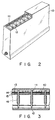
- long plate-like support members 11 As shown in Figs. 2 and 3, there are used long plate-like support members 11 or needle-like support members the supporting atmospheric pressure, which is applied to a flat envelop 10 whose inside is vacuum-exhausted.
- the long plate-like support members 11 are used in order to prevent load of atmospheric pressure from concentrating on one point by supporting a screen 12 at the large contact area.
- the plate-like support members are strong against the deformation in a direction in a surface, but easily deformed in the direction other than the inner surface direction. As shown in Fig. 5, deformation 11b is easily generated during a fixture or a heating process.
- the needle-like support members there is a problem in the number of the needle-like support members, which are necessary to support atmospheric pressure.
- the contact area between the plate-like support members and glass is relative large.
- the contact area between the needle-like support members and glass is extremely small, and considerably large number of needle-like support members are needed in order to reduce load weight of each support members.
- the needle-like support members must be arranged with a pitch of 10 mm or less, and there are needed 1000 or more needle-like support members in order to support atmospheric pressure, which is applied to the sheet glass whose size corresponds to 20 inches of the diagonal size of the screen.
- the top end portion of the member must be processed to be needle-like.
- a method for processing a wire material to be needle-like can be easily processed by a cylindrical grinding.
- the plate-like or needle-like support members are not favorable for practical use in view of the structure, manufacturing as a part, assembling, and the cost thereof.
- the conventional flat cathode-ray tubes which have been proposed, include a large number of wire cathodes 13, a large number of control electrodes 14, accelerating electrodes 15, deflecting electrodes 16 therein.
- the structure is very complicated, and there are many problems in the manufacture. If the large-sized screen is used, the manufacture of the cathode-ray tube becomes extremely difficult.
- a large number of support members and the inner electrodes there occurs a problem on occluded gas of these members. As a result, a life characteristic of the cathode-ray tube is largely deteriorated, and this is considerably unfavorable for practical use.
- An object of the present invention is to provide a flat display device having high practical use and high industrial value.
- a display device comprising: a vacuum envelope including a first flat plate having an inner surface and a thickness t and a second flat plate faced to the inner surface of said first plate; a fluorescent screen formed on the inner surface of said first plate; means for generating first electron beams which dividedly scan said fluorescent screen, respectively; and a plurality of support members for supporting said first and second plates, which are provided between said first and second plates and are arranged on said screen at a predetermined interval P, wherein a ratio t/P is 0.05 or more.
- a display device comprising: a vacuum envelope including a first flat plate having an inner surface and a thickness t and a second flat plate faced to the inner surface of said first plate; a fluorescent screen formed on the inner surface of said first plate; means for generating first electron beams which dividedly scan said fluorescent screen, respectively; and a plurality of support members for supporting said first and second plates, which are provided between said first and second plates and are arranged on said screen at a predetermined interval, each of said support members having a top end portion contacting said screen and the top end portion being formed into a wedge-shape and have a length of 2 mm to 3 mm along its longitudinal direction.
- a screen is formed in the inner surface of a glass faceplate, which is a flat first plate.
- the flat rearplate which is used as a second plate forming the vacuum envelop together with the first plate, is arranged to be opposed to the glass faceplate.
- support members to support against atmospheric pressure between these plates.
- a plurality of electron gun assemblies which generates an electron beam, is arranged to be opposed to the screen.
- the support members are arranged on the screen to maintain predetermined intervals P. In a case where a ratio t/P is 0.05 or more wherein the thickness of the faceplate is t, the number of support members can be largely reduced with the minimum thickness of the faceplate. Due to this, the weight of the display device can be reduced, and the number of support members is small, so that the manufacture can be made extremely easily.
- the distance between the electron gun and the screen can be made minimum and set in the same manner, the magnification of the electron lens in the electron gun can be made small, the stop on the screen can be made small, thereby an image having high resolution can be formed.
- the depth of the display device can be shortened, and the weight of the display device can be reduced as compared with the area of the screen, thereby an image having good visibility can be formed on the screen.
- the display segment regions which correspond to the screen portion of a plurality of independent picture tubes, are formed in the inner surface of the flat faceplate and the flat rearplate, and the support members are arranged between these plates.
- the side end portion of the first plate of the support members is wedge-shaped.
- the length in a longitudinal direction of the wedge-shaped end portion is set to 2 mm to 30 mm, thereby the thickness of the faceplate can be thinned as much as possible, and the number of the support members can be largely reduced. Due to this, the weight of the display device can be reduced, and the number of support members is small, so that the manufacture can be made extremely easily.
- the distance between the electron gun and the screen can be made minimum and set in the same manner, the magnification of the electron lens can be made small, the stop on the screen can be made small, thereby an image having high resolution can be formed.
- the depth of the display device can be shortened. Since the screen is flat, an image having extremely good visibility can be formed on the screen. In addition to these advantages, there can be provided a display device having high practical use and high industrial value.
- the display segment regions which correspond to the screen of the plurality of independent picture tubes, are formed in the inner surface of the flat faceplate, and a plurality of openings is formed in the rearplate, and support members are arranged between the plates to ensure the interval between these plates against atmospheric pressure.
- the funnel is continuous from the opening of the rearplate, and the neck portion is continuous from the funnel.
- each electron gun which is an electron source
- the screen can be made minimum and set in the same manner, the magnification of the electron lens can be made small, and the beam stop on the screen can be made small, and an image having high resolution can be obtained.
- the depth of the display device can be shortened. Since the screen is flat, an image having extremely good visibility can be formed on the screen.
- the structure is considerably simple, and the support members are provided, so that the faceplate and the rearplate can be thinned and the weight of the display device can be reduced.
- FIG. 6 to 10 show a cathode-ray tube type display device of an embodiment of the present invention.
- Fig. 6 is a perspective view showing the entire structure
- Figs. 7 and 8 are cross sectional views of Fig. 6.
- a display device 20 comprises a vacuum envelop including a flat faceplate 21, a side wall 22, which is provided around the faceplate 21 and extends in a direction, which is substantially perpendicular to the face plate, a rearplate 23 opposing to the faceplate 21, a plurality of funnels 24 and a plurality of necks 25, which are continuous to the rearplate 23.
- an electron gun assembly 26 In each neck 25, there is enclosed an electron gun assembly 26 generating single electron beam or red, green and blue, electron beams.
- a deflection device (not shown).
- the faceplate 21 is formed of flat glass, and a monochromatic fluorescent layer is formed or color fluorescent layers are formed on the faceplate 21, thereby forming a fluorescent screen 30.
- the electron beam emitted from each electron gun assembly is deflected and scans the fluorescent layer so that light rays are emitted from the fluorescent screen 30.
- rasters R1, R2, R3 ... R20 which correspond to small segments each having substantially the same size, are drawn. These small raster regions are connected by a signal applied to the electron guns and the deflection device, and one large raster is formed on the entire screen. As shown in Fig.
- the rearplate 23 is also formed of glass, an opening 27 is formed at a predetermined position, and the funnels 24 are bonded to the rearplate 23 around the openings 27.
- a top end portion 31a of the support rod 31 is wedge-shaped, and the thin flat faceplate 21 and the rearplate 23 are supported at a predetermined interval against atmospheric pressure.
- the support rod 31 is positioned at the portion between the adjacent segment regions, that is, a crossing point 32 of the boundary lines between the rasters regions of the screen.
- the vacuum envelop including the flat faceplate 21, the side wall 22, which extends in a direction, which is substantially perpendicular to the faceplate 21 from the periphery portion of the faceplate 21, the rearplate 23, which is faced to the faceplate 21 and arranged substantially parallel to the faceplate 21 at a predetermined interval
- high atmospheric pressure is applied to the entire envelop. Due to this, for example, in a faceplate having a size of 20 inches, force of 1 ton or more is applied to the entire surface of the faceplate.
- the number of support members is increased, stability can be obtained. However, this is unfavorable in terms of productivity, and a life characteristic is deteriorated, because of difficulty in dealing with occluded gas.
- the inventors of the present invention carried out simulation to be explained later. They studied the relationship between the thickness of the faceplate and the interval of the adjacent support members, and found out that a ratio t/P should be set to 0.05 or more where the thickness of the faceplate is t and the interval between the adjacent support members is P.
- the inventors variously studied withstand stress against atmospheric pressure of the flat glass faceplate by an experiment using a rectangular vacuum device 40 whose inner size is 300 mm in length and 400 mm in width shown in Fig. 11 and stress computer simulation.
- glass has the size corresponding to 20 inches, that is, diagonal distance of 500 mm
- glass is destroyed by atmospheric pressure under vacuum if the thickness of the plate is not set to 15 mm or more. If a vacuum pump 41 is operated and the space between glass plate of the vacuum device 40 and the vacuum pump 41 is exhausted, glass 50 is curved from a mounting position 52 on a support frame 51 as shown in Fig. 12A, so that the thin glass plate cannot withstand atmospheric pressure without support members.
- a vaccum envelop of a cathode-ray tube having a spherically curved glass faceplate
- the thickness of the peripheral portion is over 20 mm.
- the peripheral edge is tightened by a tension band, and the maximum stress is designed to be about 1000 PSI (pound per square inch).
- PSI pounds per square inch
- glass plate can withstand atmospheric pressure if the thickness is 10 mm or more. As shown in Fig. 12C, if nine support members 53 are arranged on the center region and mid-region of the glass plate, deformation of glass is further reduced, glass plate can withstand atmospheric pressure if the thickness is 4.5 to 5 mm or more.
- the thickness of the glass plate cannot be reduced in proportion to increase in the number of support members.
- Fig. 13 showing the relationship between the number A of support members, which are arranged in the device of Fig. 11 at equal intervals, and the thickness t of glass plate withstanding destruction, the limitation of the thickness, which can withstand atmospheric pressure was 2 mm.
- the relation ship between the number A of the support members and the thickness of glass is in the region shown by oblique lines, glass can withstand atmospheric pressure.
- the ratio t/P is larger than a predetermined value where the thickness of the faceplate 50 is t and the interval between the adjacent support members 53 is P, there is little amount l of deformation of faceplate 50, thereby no destruction due to deformation may occur. If the ratio t/P is smaller than the predetermined value, the amount l of deformation of the faceplate increases and destruction occurs. In order to withstand the inner deformation of glass, it is necessary to avoid generating much deformation, and the thickness of glass must be reserved to some extent.
- Table 1 shows ratio t/P, which was calculated from the result of the experiment of Fig. 13.
- Table 1 Thickness t (mm) Members of Glass plate Number of Support Members Interval P (mm) between support Members Ratio t/P 10 1 175 0.057 6 4 117 0.051 4.5 9 87.5 0.051 4 16 70 0.057 3 25 58 0.052 2.5 36 50 0.050
- ratio t/P of 0.05 or more is required in order that the sheet glass withstands atmospheric pressure.
- the number of the crossing points of the segment regions is 16. Then, if the support members are provided on each crossing point, the number of support members is 16.
- the horizontal size of the screen is about 400 mm and the vertical size thereof is about 300 mm
- each divided segment region is about 80 mm in horizontal size and about 60 mm in vertical size
- the interval P between the adjacent support members is about 70 mm in horizontal and vertical sizes on the average. Therefore, if the thickness of glass faceplate is 4 mm, t/P is 0.057 and this can sufficiently withstand atmospheric pressure.
- the number of support members is 81 since the interval P between the support members is about 70 mm in horizontal and vertical sizes on the average when the thickness of the faceplate is 4 mm. Also, if the interval p between the support members is set double, that is, 140 mm, the total number A of support members may be 16, and the minimum thickness of glass faceplate is 7 mm.
- the selection of the thickness of glass faceplate and the number of support members can be determined in consideration of the total weight of the display device, dead load against the area of the faceplate, and impact resistance. In other words, it is important to consider lightening weight by thinning the glass thickness of the faceplate, disadvantage in which the number of support members must be increased, increasing weight by increasing the glass thickness of the faceplate, and reserving impact resistance as well as atmospheric pressure resistance.
- a 20-inch faceplate having an aspect ratio of 3 : 4.
- the screen is divided into 5 horizontal segment regions and 4 vertical segment regions. Since 16 crossing points are provided and rod-like support members is provided on each crossing point, the number of support members is 12. Since the interval P between the adjacent support members is about 80 mm in the horizontal direction and about 75 in the vertical direction, 78 mm of average pitch is obtained. Therefore, t/P is 0.051 if the thickness of the glass faceplate is 4 mm. Even if the thickness is 5 mm in consideration of safety, there can be achieve a vaccum envelop having light weight and sufficient strength against atmospheric pressure. Since the number of support members is only 12, the entire display device can be easily manufactured. Moreover, the discharge of occluded gas under vacuum can be ignored, and the life of the display device is not deteriorated.
- the weight of the faceplate is only about 1.8 kg. This is made much lighter than the same-sized faceplate of the conventional display device having weight of about 9 kg, and the weight of the entire display device is considerably lightened.
- the thickness t of the faceplate is 2 mm or more and the interval P between the adjacent rod-like support members is set to be a ratio t/P of 0.05 or more.
- the number of support members is preferably reduced in view of the operation of the tube. Since the peripheral edge of the faceplate is supported by the side wall of the vaccum envelope, resistance against atmospheric pressure at the pheripheral edge is higher than that of the central portion of the faceplate. When a distance between the side wall and the support member adjacent to the side walls is shorter than the interval between the support members on the central portion of the faceplate, the number of support members can be reduced. The number of support members can be also reduced if the thickness of the faceplate is made large. However, in consideration of the weight of the faceplate and that of the cathode-ray tube, the faceplate is preferably formed as thin as possible. Therefore, for example, the faceplate having a thickness of 15 mm or more is not favorable for practical use.
- the thickness of the faceplate is thinner than the conventional cathode-ray tube having no support members.
- the thickness of the faceplate is preferably 10 mm or less, and more preferably the faceplate has a thickness of about 5 mm, which is light in weight and favorable for practical use in view of the treatment.
- the adjacent electron gun assemblies In the cathode-ray tube having the screen which is dividedly scanned by the electron beams, as explained in the embodiment, the adjacent electron gun assemblies must be positioned to be separated to a certain extent.
- the interval that is, the distance between center axes of the adjacent electron gun assemblies cannot be set to be 15 mm or less.
- the support members In a case where the support members are arranged on the crossing points of the divided regions of the screen, the interval of the arrangement must be at least 15 mm or more. Therefore, in the embodiment of the present invention, it is difficult to realize the plate whose upper limit of the ratio t/P is over 1.0.
- the value of t/P by which the effect of the present invention is considerably brought about is 0.67 or less, and 0.33 or less is preferably.
- the rod-shaped support members whose end portions are wedge-shaped.
- the top end portion can be needle-shaped.
- the screen is formed of a three-colored stripe fluorescent member including a black stripe
- the top end portion of the support material is preferably arranged on the black stripe so that a non-emitting portion corresponding to the contacting point of the support members can not be conspicuous.
- the width of the black stripe is only 100 ⁇ m, it is difficult to accurately adjust the top end portion of the support member onto the black stripe.
- the screen may be broken.
- linear length of the top end portion of the support members may be shortened without being integrated with the top ends of the adjacent support members in the longitudinal direction.
- the above embodiment explained the structure wherein the funnels and the necks are connected to the rearplate shown in Figs. 6 to 10 and the electron gun assemblies are provided in the necks respectively.
- the present invention is not limited to the above-mentioned structure. More specifically, the present invention can be applied to the structure wherein the opposing two flat plates are supported by the support members.
- the present invention can be further made smaller the lower limit value of the interval between the support members in the structure of the electron gun as shown in the above embodiment.
- ratio t/P may be suitably set in accordance with the structure of the display device to be used.
- the entire structure is the same as the structure explained in the first embodiment shown in Figs. 6 to 10.
- the interval between the faceplate and the rearplate is 20 mm
- the height of the support members 31 shown in Fig. 14 is 20 mm.
- the top end portion of a metal round bar having a diameter of 15 mm is wedge-shaped by a mechanical process.
- a wedge-shaped top end portion 31a whose a width W is 0.05 mm and a length L in the longitudinal direction of the top end portion is 15 mm, which is the same size as the diameter of the metallic round rod.
- the wedge-shaped top end portion 31a contacts a black stripe of the screen 30 and the width of the black stripe is 0.07 mm.
- the size of the fluorescent screen 30, which is formed on the inner surface of the faceplate 21 is about 400 mm ⁇ 300 mm, and atmospheric pressure applied to the faceplate 21 is supported by 12 support members 31.
- the first destruction factor is determined by the relationship between the thickness of the glass faceplate and the interval of the support members 31 as shown in the first embodiment.
- the second destruction factor is determined by the shape and size of the top end portion of the support members 31 and to be explained later.
- the faceplate is deformed by atmospheric pressure in its relatively large region between the adjacent support members. By this deformation, stress in compression is generated in the outer surface of the faceplate, and stress in tension is generated in the inner surface of the faceplate. Stress destruction occurs when the stress in tension exceeds a critical value.
- a contour line (equivalent stress line) of the maximum stress which is close to the portion where the support members and the sheet glass are in contact, is obtained by a calculator simulation using a finite element method. Then, a state of stress concentration can be determined from the degree of the density of the pitch of the contour line. Moreover, in this type of calculator simulation, it is extremely difficult to accurately calculate an absolute value of the stress of the contact portion between the top end portion and glass. Also, such an absolute value is meaningless in the estimation of the stress concentration and the stress distribution. Therefore, the state of stress concentration from the stress distribution close to the periphery of the contact portion (relative value comparison).
- the state in which glass is broken by the stress concentration is that the equivalent stress line having a high value is distributed to one point with close pitches.
- the sheet glass is deformed to be loaded on one point even if the top end portion of the support members has a certain degree of the length. Therefore, the state of the sheet glass can be discriminated by looking at the state of equivalent stress line whether the sheet glass is supported at one point or on the line having a certain area.
- the inventors obtained the necessary minimum length by variously changing the length of the contact portion (length in the longitudinal direction of the top end portion of the support members) for holding atmospheric pressure to be applied to the sheet glass on the line having a certain area.
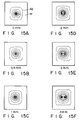
- Figs. 15A to 15F and Figs. 16A to 16F are views showing the stress distributions obtained by the above simulation. There are provided 12 types of lengths L (0 to 20 mm) in the longitudinal direction (length 0 mm is a case wherein the sheet glass is supported on one point).
- Figs. 15A to 15F and 16A to 16F in a case where the length in the longitudinal direction of the top end portion of the support members 31 is below 2 mm (support on one point, 0.5 mm and 1 mm) as shown in Figs. 15A, 15B and 15C, the stress concentrates on substantially one point 61 (small area), and the pitches of the equivalent stress line are narrow, and it is understood that the abrupt concentration is performed.
- Fig. 15D the stress is smoothly distributed to have a relatively large area at the time when the length in the longitudinal direction exceeds 2 mm.
- one equivalent stress line having the highest stress value appears as a small circle in the central portion corresponding to the top end portion. Therefore, it can be understood that the support members 31 having such a length of the top end portion functions similar to the support members 31 having the dot-like top end portion. In the stress distribution view in which the length is 2 mm, two equivalent stress lines having the same size appear in parallel in the portion corresponding to the top end portion. It can be understood that there is a tendency for the stress of one point concentration type to be relaxed.
- the length in the longitudinal direction of the top end portion of the support members must be at least 2 mm or more.
- the stress in which the length in the longitudinal direction is 2 mm or more becomes smooth in accordance with the length in the longitudinal direction as mentioned above. Further, the absolute value of the stress decreases as the contact area between the sheet glass and the support members increases.
- the inventors found out from the result of the calculator simulation that the minimum value of the length in the longitudinal direction of the top portion of the support members to effectively hold atmospheric pressure was 2 mm. However, in consideration of the practical use and safety, it is preferably that the length of the top end portion is set to be slightly longer.
- the width of the top end portion of the support members was set to 0.05 mm in the result of the calculator simulation shown in this embodiment. However, the similar result was obtained in the case in which the width of the top end portion was up to at least 0.5 mm.
- the process of the support members and the assembly become difficult as the length L of the top end portion in the longitudinal direction is made longer.
- the degree of parallel of the top end portions is extremely important.
- the maximum length is 30 mm in view of practical use, that is, productivity.
- a long member of the top end portion in the longitudinal direction is unfavorable.
- the accuracy of position and the degree of parallel between the black stripe and the longitudinal direction of the top end portions are extremely important at the time of assembly.
- the accuracy limit at the time when the normal support members are assembled in parallel is 0.02° for practical use.
- the length of the top end portion of the support members is about 30 mm or more, the assembly of the support members becomes considerably difficult.
- each support member is wedge-shaped and formed of a relatively thick metallic round rod. Therefore, the area contacting the rear panel is large, and these support members can be relatively easily assembled with high accuracy.
- each support members of the above embodiment has the cross section of the end portion 31b of the rear side, which is formed circle, and the end portion 31a is formed into a wedge-shape.
- a plate-like support member 70 or a square timber-like support members 71 may be used, or the support members are partially or wholly connected to the other members. If the top end portion of the support member is wedge-shaped and has a length of 2 to 30 mm in the longitudinal direction, the function of the present invention and the effect can be exerted.
- the present invention can be applied to a case in which a plurality of support members are partially or wholly integrated.
- metal is used as a material for the support members.
- glass and ceramic may be applied to the present invention.
- the present invention is not limited to the above-mentioned structure.
- the present invention may be applied to a structure in which the opposing two flat plates is supported by the support members.
- the present invention may be used to the display device to which a linear wire cathode and electrostatic deflection are combined.
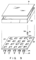
- a third embodiment as shown in Fig. 9, there is used flat glass material as a rearplate having a substantially rectangular opening 27 formed at predetermined position.
- the opening 27 can be formed by a method in which abrasive composition is blown with high pressure air or high pressure water, a method using laser-melting, a method using ultrasonic wave, or a method using a grinding stone. According to these methods, the opening can be easily formed at an ordinary temperature. It is possible to form the opening 27 by a secondary forming method in which glass is heated at over a glass softening point. Moreover, a press-forming can be used in forming the opening 27.
- Faceplate 21, rearplate 23, and side wall 22 are formed of glass plates, which are all the same thickness and the same material.
- Funnel 24 is formed by a blowing method. Regarding the bonding the respective members, heat melt method can be used in the necks 25, the funnels 24, and the rectangular side of the side walls 22, frit glass is used in the other portions.
- One faceplate, four side walls, one rearplate, and a plurality of funnels and the necks are formed of all glass plates. Thereby, there can be provided a display device whose total depth length is shorter without using the faceplate and the rearplate, which have curvature as in the conventional cathode-ray tube.
- the support members 31 are supported by the support members 31 and sufficient strength can be obtained by relatively thin glass material raging from 4 mm to 15 mm, which is preferable for weight and strength. Due to this, the weight of the cathode-ray tube is considerably lighter than than that of the conventional cathode-ray tube. Further, deformation of the plates due to atmospheric pressure can be made extremely small by use of the support members 31. The amount of deformation is zero at the position where the support members are provided, and maximum at the center of each divisional scanning region. The amount of deformation is substantially symmetrically distributed relative to the center. The central axis of the electron gun, which is arranged on the extended line of the center of the deformation, is not completely inclined after deformation.
- the central axis of the electron gun can be maintained to be perpendicular to the screen.
- the support members must be arranged on the boundary line of the each divisional scanning region where shadow and reflection are not generated by the support members, even if the electron beam is deflected and scanned.
- the support members are used as mentioned above, deformation of the envelop due to atmospheric pressure can be extremely made small, and the distribution of deformation in the each divisional scanning region can be made to be substantially symmetrically to the center of the region.
- the central axis of the electron gun can be arranged to be perpendicular to the fluorescent surface in any regions. This is an extremely large disadvantage for the cathode-ray tube having an electron beam generating section in the rearplate.
- the distance between the electron gun and the fluorescent screen can be relatively easily shortened, magnification of the electron lens can be made smaller, and an image having high resolution can be easily displayed.
- glass is used as a rearplate in the structure of the present invention, a space through which the electron beam passes can be more easily made to be a equipotential space having high potential than the structure using a metallic plate. Therefore, unlike the metallic plate, there is no need for the entire rearplate to be insulated. Moreover, it is possible to prevent mutual interference, which is generated through the metallic plate of the magnetic field of the adjacent deflection devices, and there is no influence of magnetization of the metallic plate.
- the rectangular openings 27 are not necessarily rectangular.
- the shape of the opening is preferably an outermost track of the electron beam, that is, raster-shape in order to lower the consumption of electric power of the deflecting yoke, which is attached to the outer wall of the funnel 24 connected to the opening.
- the openings are formed in the flat rearplate, and the funnels and the necks are connected to the openings. Due to this, it is possible to largely reduce the consumption of electric power of the deflection device by thinning glass of the funnel, which cannot be made in the conventional cathode-ray tube.
- the above embodiment explained the structure in which the rearplate and the funnels and the necks were separately formed and these members were enclosed.
- the present invention is not limited to the above embodiment. It is possible to integrally form the rearplate, and the funnels and the necks.
- a fourth embodiment will be explained.
- the entire structure of the fourth embodiment is similar to the above-mentioned embodiment, as shown in Figs. 6 to 10, there are arranged the rod-shaped support members 31 as support members between the faceplate 21 and the rearplate 23.
- the top end portion 31a of each support members 31 is wedge-shaped, and the base portion 31b is adhered to the portion if the rearplate to which the funnel are connected.
- These support members are used to support the faceplate and the rearplate from atmospheric pressure. Due to this, there may have a contact area to a certain extent since deformation of glass of the contact portion between the support members and glass must be controlled at a minimum.
- the support members are wedge-shaped,and arranged in either direction of the screen. If there is used a color cathode-ray tube screen wherein striped absorbing materials, that is, the black strips are formed between the striped fluorescent members, the wedge-shaped top end portions may be arranged along the striped absorbing materials.
- the size of the fluorescent screen 30, which is formed in the inner surface of the faceplate 21, is about 400 mm ⁇ 300 mm, and atmospheric pressure to be applied to the faceplate is supported by 12 support members 31.
- the top end portions of the support member contact crossing points 32 on the boundary lines between the divided segment regions R1 ... of the screen as shown in Fig. 5, and the total number of the crossing points is 12.
- the first factor is determined by the relationship between the thickness of the glass faceplate and interval of the support members.
- the second factor is determined by the shape and size of the top end portions of the support members.
- the faceplate is deformed by atmospheric pressure in its relatively large area of the region between the adjacent support members. By this deformation, stress in compression is generated in the outer surface of the faceplate, and stress in tension is generated in the inner surface of the faceplate. Stress destruction occurs when the stress in tension exceeds a critical value.
- stress destruction occurs by stress in tension, which concentratively generates in glass in the vicinity of the top end portions of the support members when the faceplate contact the support members.
- the weight of the faceplate is only about 1.8 kg, and is considerably lightened as compared with the case in which the faceplate of the conventional tube having the same size is about 9 kg. Then, the entire weight of the cathode-ray tube is considerably lightened.
- the screen is divided into five in a horizontal direction and four in a vertical direction. Therefore, crossing points 32 of the divided regions R1 ... of the screen shown in Fig. 10 are 12, and the rod-shaped support members are provided in these portions. Therefore, the number of support members is 12.
- the interval P between the support members is about 80 mm in a horizontal direction and about 75 mm in a vertical direction, and the average interval is 78 mm. Therefore, ratio t/P is 0.064.
- the interval between the faceplate 21 and the rearplate 23 is 20 mm in the entire surface of the screen 30, and the height of the support members are also 20 mm.
- the top end portions of the support members 31, which are formed of metallic-round rod of having a diameter of 15 mm, are wedge-shaped by a mechanical process.
- the widths W of the wedge-shaped top ends 31a are 0.05 mm, and the lengths L of the top end portions in the longitudinal direction are 15 mm, which is the same as the diameter of the metallic-round rod.
- the wedge-shaped top end portions 31a are in contact with the black stripes, which are a light absorbing layer of the screen 30, the widths of the black stripes are 0.07 mm. Since the number of support members is only 12, the manufacture thereof is simple and discharging occluded gas under a vacuum state can be ignored, and this does not cause deterioration of the life of the cathode-ray tube.
- the thickness t of the faceplate is 2 mm or more, and the interval P between the adjacent support members is set to obtain ratio t/P of 0.050 or more.
- the support members wherein the top end portions are wedge-shaped and the lengths of the top end portions in the longitudinal direction are 2 mm or more, sufficient strength can be given to the second destruction factor, which occurs by stress in tension concentratively generating in the glass in the vicinity of the top end portions of the support members when the faceplate glass is in contact with the support members.
- the second destruction factor which occurs by stress in tension concentratively generating in the glass in the vicinity of the top end portions of the support members when the faceplate glass is in contact with the support members.
- the number of support members is preferably reduced in view of the operation of the tube. Since the peripheral edge of the faceplate is supported by the side wall of the vacuum envelope, resistance against atmospheric pressure at the peripheral edge is higher than that of the central portion of the faceplate. When a distance between the side wall and the support members adjacent to the side walls is shorter than the interval between the support members on the central portion of the faceplate, the number of support members can be reduced. The number of support members can be reduced if the thickness of the faceplate is made large. However, in consideration of the weight of the faceplate and that of the cathode-ray tube, the faceplate is preferably formed as thin as possible. Therefore, for example, the faceplate having a thickness of 15 mm or more is not favorable for practical use.
- the thickness of the faceplate is thinner than that of the conventional cathode-ray tube having no support members.
- the thickness of the faceplate is preferably 10 mm or less, and the faceplate having a thickness of about 5 mm is light and favorable for practical use in view of the treatment.
- the adjacent electron guns in the cathode-ray tube, which devisionally scans the screen by a plurality of electron guns, the adjacent electron guns must be positioned to be separated to a certain extent.
- the interval that is, the distance between the center axes of the adjacent electron guns cannot be set to be 15 mm or less, depending on the structure of the electron guns
- the interval of the arrangement In a case where the support members are arranged on the crossing points of the boundary lines of the divided regions of the screen, the interval of the arrangement must be at least 15 mm or more. Therefore, it is difficult to obtain the plate whose upper limit of the ratio t/P is over 1.0.
- the value of t/P by which the effect of this embodiment is considerably brought about is 0.67 or less, and 0.33 or less is preferably.
- the processing the members since it is necessary for the top end portions to contact the surface of the sheet glass in parallel, the degree of parallel of the top end portions are extremely important. Then, since it is difficult for the extremely long top end portions in the longitudinal direction to be processed, the limit of the length is 30 mm in view of practical use, that is, productivity. Moreover, in consideration of the forming accuracy of the sheet glass, a long members of the top end portions in the longitudinal direction are unfavorable.
- the assembly since the top end portions must be arranged on the black stripes, the accuracy of position and the degree of parallel between the black stripes and the longitudinal direction of the top end portions are extremely important at the time of assembly. The accuracy limit at the time when the normal support members are assembled in parallel is 0.02° in view practical use.
- the length of the top end portions of the support members are about 30 mm or more, the assembly of the support members becomes considerably difficult.
- the lengths of the top end portions in the longitudinal direction are set to 15 mm.
- each support member is wedge-shaped, and formed of a relatively thick metallic round rod. Therefore, the area contacting the rear panel is large, and these support members can be relatively easily assembled with high accuracy.
- the above embodiment explained the structure in which the electron gun assemblies serving as electron sources are received in the necks formed in the second plate opposing to the small regions to devisionally scanned.
- the relationship between the interval between the support members and the thickness of the faceplate, and the shape of the top end portions of the support members are not limited to the above-mentioned structure. More specifically, the present invention is extremely useful to a display device wherein the supporting members are arranged between the faceplate to which the fluorescent screen is formed and the rear plate opposing to the faceplate, and supported at a predetermined interval, and the fluorescent screen is divided into a plurality of the small regions by a plurality of opposing electron sources, and scanned thereon.
- the present invention is applied to the display device to which the linear cathode and the electrostatic deflection are combined, it is possible to further reduce the lower limit value of the interval between the adjacent support members in the structure of the electron guns shown in the above-mentioned embodiment.
- the range of the ratio t/P to be obtained is widened.
- the ratio t/P may be suitably set to adjust to the display device to which the present invention will be applied.
- the screen which is divided into a plurality of regions and scanned thereon, is integrally structured, the flat sheet glass is used as a faceplate having the screen, and the flat sheet glass is also used as a rearplate to which the side walls, which are connected to the faceplate, and the funnels and the necks are connected to be parallel to the faceplate.
- the support members are provided between these flat glasses according to a predetermined relationship, so that the vacuum envelop with a small number of support members and the flat faceplate can be formed.
- the faceplate and the rearplate are flat and the distance between each electron gun and the screen can be set to be minimum, magnification of the electron lens of the electron beam can be made small, and the spot on the screen is made small, thereby forming an image having high resolution.
- the depth of the device can be shortened, the weight thereof can be largely reduced as compared with the area of the screen, and the screen can provide clear images.
Landscapes
- Cathode-Ray Tubes And Fluorescent Screens For Display (AREA)
- Vessels, Lead-In Wires, Accessory Apparatuses For Cathode-Ray Tubes (AREA)
Applications Claiming Priority (6)
| Application Number | Priority Date | Filing Date | Title |
|---|---|---|---|
| JP216207/90 | 1990-08-16 | ||
| JP21620790 | 1990-08-16 | ||
| JP22628890 | 1990-08-28 | ||
| JP226288/90 | 1990-08-28 | ||
| JP33670190 | 1990-11-30 | ||
| JP336701/90 | 1990-11-30 |
Publications (3)
| Publication Number | Publication Date |
|---|---|
| EP0471359A2 true EP0471359A2 (de) | 1992-02-19 |
| EP0471359A3 EP0471359A3 (en) | 1992-06-03 |
| EP0471359B1 EP0471359B1 (de) | 1997-03-19 |
Family
ID=27329851
Family Applications (1)
| Application Number | Title | Priority Date | Filing Date |
|---|---|---|---|
| EP91113654A Expired - Lifetime EP0471359B1 (de) | 1990-08-16 | 1991-08-14 | Flache Anzeigevorrichtung |
Country Status (4)
| Country | Link |
|---|---|
| US (1) | US5287034A (de) |
| EP (1) | EP0471359B1 (de) |
| KR (1) | KR940009320B1 (de) |
| DE (1) | DE69125224T2 (de) |
Cited By (5)
| Publication number | Priority date | Publication date | Assignee | Title |
|---|---|---|---|---|
| WO1993021651A1 (en) * | 1992-04-21 | 1993-10-28 | Kabushiki Kaisha Toshiba | Cathode ray tube apparatus and method of manufacturing the same |
| GB2276270A (en) * | 1993-03-18 | 1994-09-21 | Ibm | Spacers for flat panel displays |
| EP0762465A1 (de) * | 1995-09-08 | 1997-03-12 | Kabushiki Kaisha Toshiba | Kathodenstrahlröhre und deren Herstellungsverfahren |
| EP0724282A3 (de) * | 1995-01-27 | 1997-09-17 | Toshiba Kk | Farbkathodenstrahlröhre und Verfahren zu ihrer Herstellung |
| EP0881660A3 (de) * | 1997-05-30 | 1999-03-10 | Kabushiki Kaisha Toshiba | Kathodenstrahlröhre und Verfahren zur Herstellung |
Families Citing this family (3)
| Publication number | Priority date | Publication date | Assignee | Title |
|---|---|---|---|---|
| TW314637B (de) * | 1995-07-27 | 1997-09-01 | Toshiba Co Ltd | |
| MY129516A (en) | 1997-05-30 | 2007-04-30 | Toshiba Kk | Image display apparatus and method of manufacturing the same |
| CN114999317B (zh) * | 2021-09-26 | 2023-01-24 | 荣耀终端有限公司 | 显示屏及其制作方法、电子设备 |
Family Cites Families (7)
| Publication number | Priority date | Publication date | Assignee | Title |
|---|---|---|---|---|
| US4145633A (en) * | 1977-05-12 | 1979-03-20 | Rca Corporation | Modular guided beam flat display device |
| US4166233A (en) * | 1977-06-13 | 1979-08-28 | Rca Corporation | Phosphor screen for flat panel color display |
| US4308484A (en) * | 1980-01-17 | 1981-12-29 | Rca Corporation | Frontplate and shadow mask assemblies for a modular flat panel display device |
| GB2110465A (en) * | 1981-11-09 | 1983-06-15 | Philips Electronic Associated | Flat panel display tube |
| NL8302966A (nl) * | 1983-08-25 | 1985-03-18 | Philips Nv | Beeldweergeefpaneel. |
| JPH0719552B2 (ja) * | 1986-05-20 | 1995-03-06 | 松下電器産業株式会社 | 平板型表示装置 |
| EP0356823B1 (de) * | 1988-08-30 | 1993-02-10 | Kabushiki Kaisha Toshiba | Farbkathodenstrahlröhre und Röhrenkolben für Farbkathodenstrahlröhren |
-
1991
- 1991-08-14 EP EP91113654A patent/EP0471359B1/de not_active Expired - Lifetime
- 1991-08-14 DE DE69125224T patent/DE69125224T2/de not_active Expired - Fee Related
- 1991-08-14 US US07/745,461 patent/US5287034A/en not_active Expired - Lifetime
- 1991-08-16 KR KR1019910014242A patent/KR940009320B1/ko not_active Expired - Fee Related
Cited By (8)
| Publication number | Priority date | Publication date | Assignee | Title |
|---|---|---|---|---|
| WO1993021651A1 (en) * | 1992-04-21 | 1993-10-28 | Kabushiki Kaisha Toshiba | Cathode ray tube apparatus and method of manufacturing the same |
| GB2276270A (en) * | 1993-03-18 | 1994-09-21 | Ibm | Spacers for flat panel displays |
| EP0724282A3 (de) * | 1995-01-27 | 1997-09-17 | Toshiba Kk | Farbkathodenstrahlröhre und Verfahren zu ihrer Herstellung |
| US5691597A (en) * | 1995-01-27 | 1997-11-25 | Kabushiki Kaisha Toshiba | Color cathode-ray tube and method for manufacturing the same |
| US5803781A (en) * | 1995-01-27 | 1998-09-08 | Kabushiki Kaisha Toshiba | Method of assembling shadow mask of CRT panel |
| EP0762465A1 (de) * | 1995-09-08 | 1997-03-12 | Kabushiki Kaisha Toshiba | Kathodenstrahlröhre und deren Herstellungsverfahren |
| US5831372A (en) * | 1995-09-08 | 1998-11-03 | Kabushiki Kaisha Toshiba | Cathode ray tube with supporting members each having a first and second support portion for improved bearing of atmospheric pressure between the faceplate and the rearplate |
| EP0881660A3 (de) * | 1997-05-30 | 1999-03-10 | Kabushiki Kaisha Toshiba | Kathodenstrahlröhre und Verfahren zur Herstellung |
Also Published As
| Publication number | Publication date |
|---|---|
| EP0471359A3 (en) | 1992-06-03 |
| DE69125224T2 (de) | 1997-08-14 |
| EP0471359B1 (de) | 1997-03-19 |
| KR920005234A (ko) | 1992-03-28 |
| DE69125224D1 (de) | 1997-04-24 |
| US5287034A (en) | 1994-02-15 |
| KR940009320B1 (ko) | 1994-10-06 |
Similar Documents
| Publication | Publication Date | Title |
|---|---|---|
| US5365142A (en) | Cathode-ray tube wherein plural regions of phosphor screen are scanned independently of one another | |
| EP0471359B1 (de) | Flache Anzeigevorrichtung | |
| JP3108468B2 (ja) | 表示装置 | |
| US6441566B2 (en) | Color cathode ray tube and color picture tube apparatus having the same | |
| KR100495514B1 (ko) | 음극선관장치 | |
| KR0181672B1 (ko) | 개선된 면판 패널을 가진 칼라 화상 튜브 | |
| US6573649B1 (en) | Color picture tube | |
| JP3110085B2 (ja) | 陰極線管 | |
| US6680566B2 (en) | Television cathode ray tube | |
| US6133675A (en) | Cathode ray tube with integral rear envelope | |
| US6177757B1 (en) | Image display apparatus with integrally rear plate and support bodies | |
| US6563258B2 (en) | Color cathode ray tube having an improved electron gun electrode | |
| CN1018968B (zh) | 具有改进的16比9的宽高比屏盘的阴极射线管 | |
| CA1125348A (en) | Cathode-ray tube having corrugated mask with increased mask-to-screen spacing | |
| JP3316044B2 (ja) | カラー表示装置の製造方法 | |
| JP2000156180A (ja) | 陰極線管 | |
| JP3253710B2 (ja) | 陰極線管 | |
| JP3362921B2 (ja) | 表示装置の製造方法及び表示装置 | |
| JPH0757664A (ja) | 陰極線管およびその製造方法 | |
| JPH0765750A (ja) | カラー受像管 | |
| JPH0729493A (ja) | 陰極線管の製造方法 | |
| JPH0757663A (ja) | 陰極線管 | |
| JPH1186762A (ja) | 陰極線管 | |
| JPH11191382A (ja) | 陰極線管 | |
| JPH1145673A (ja) | 画像表示装置およびその製造方法 |
Legal Events
| Date | Code | Title | Description |
|---|---|---|---|
| PUAI | Public reference made under article 153(3) epc to a published international application that has entered the european phase |
Free format text: ORIGINAL CODE: 0009012 |
|
| 17P | Request for examination filed |
Effective date: 19910911 |
|
| AK | Designated contracting states |
Kind code of ref document: A2 Designated state(s): DE FR GB |
|
| PUAL | Search report despatched |
Free format text: ORIGINAL CODE: 0009013 |
|
| AK | Designated contracting states |
Kind code of ref document: A3 Designated state(s): DE FR GB |
|
| 17Q | First examination report despatched |
Effective date: 19950308 |
|
| GRAG | Despatch of communication of intention to grant |
Free format text: ORIGINAL CODE: EPIDOS AGRA |
|
| GRAH | Despatch of communication of intention to grant a patent |
Free format text: ORIGINAL CODE: EPIDOS IGRA |
|
| GRAH | Despatch of communication of intention to grant a patent |
Free format text: ORIGINAL CODE: EPIDOS IGRA |
|
| GRAA | (expected) grant |
Free format text: ORIGINAL CODE: 0009210 |
|
| AK | Designated contracting states |
Kind code of ref document: B1 Designated state(s): DE FR GB |
|
| REF | Corresponds to: |
Ref document number: 69125224 Country of ref document: DE Date of ref document: 19970424 |
|
| ET | Fr: translation filed | ||
| PLBE | No opposition filed within time limit |
Free format text: ORIGINAL CODE: 0009261 |
|
| STAA | Information on the status of an ep patent application or granted ep patent |
Free format text: STATUS: NO OPPOSITION FILED WITHIN TIME LIMIT |
|
| 26N | No opposition filed | ||
| REG | Reference to a national code |
Ref country code: GB Ref legal event code: 746 Effective date: 19981023 |
|
| REG | Reference to a national code |
Ref country code: FR Ref legal event code: D6 |
|
| REG | Reference to a national code |
Ref country code: GB Ref legal event code: IF02 |
|
| PGFP | Annual fee paid to national office [announced via postgrant information from national office to epo] |
Ref country code: DE Payment date: 20070809 Year of fee payment: 17 |
|
| PGFP | Annual fee paid to national office [announced via postgrant information from national office to epo] |
Ref country code: GB Payment date: 20070809 Year of fee payment: 17 |
|
| PGFP | Annual fee paid to national office [announced via postgrant information from national office to epo] |
Ref country code: FR Payment date: 20070808 Year of fee payment: 17 |
|
| GBPC | Gb: european patent ceased through non-payment of renewal fee |
Effective date: 20080814 |
|
| REG | Reference to a national code |
Ref country code: FR Ref legal event code: ST Effective date: 20090430 |
|
| PG25 | Lapsed in a contracting state [announced via postgrant information from national office to epo] |
Ref country code: DE Free format text: LAPSE BECAUSE OF NON-PAYMENT OF DUE FEES Effective date: 20090303 Ref country code: FR Free format text: LAPSE BECAUSE OF NON-PAYMENT OF DUE FEES Effective date: 20080901 |
|
| PG25 | Lapsed in a contracting state [announced via postgrant information from national office to epo] |
Ref country code: GB Free format text: LAPSE BECAUSE OF NON-PAYMENT OF DUE FEES Effective date: 20080814 |