EP0471478A2 - Appareil d'affichage à grand écran - Google Patents
Appareil d'affichage à grand écran Download PDFInfo
- Publication number
- EP0471478A2 EP0471478A2 EP91307066A EP91307066A EP0471478A2 EP 0471478 A2 EP0471478 A2 EP 0471478A2 EP 91307066 A EP91307066 A EP 91307066A EP 91307066 A EP91307066 A EP 91307066A EP 0471478 A2 EP0471478 A2 EP 0471478A2
- Authority
- EP
- European Patent Office
- Prior art keywords
- screen
- projection
- transparent plate
- display device
- optical image
- Prior art date
- Legal status (The legal status is an assumption and is not a legal conclusion. Google has not performed a legal analysis and makes no representation as to the accuracy of the status listed.)
- Granted
Links
Images




Classifications
-
- H—ELECTRICITY
- H04—ELECTRIC COMMUNICATION TECHNIQUE
- H04N—PICTORIAL COMMUNICATION, e.g. TELEVISION
- H04N9/00—Details of colour television systems
- H04N9/12—Picture reproducers
- H04N9/31—Projection devices for colour picture display, e.g. using electronic spatial light modulators [ESLM]
- H04N9/3141—Constructional details thereof
- H04N9/3147—Multi-projection systems
-
- H—ELECTRICITY
- H04—ELECTRIC COMMUNICATION TECHNIQUE
- H04N—PICTORIAL COMMUNICATION, e.g. TELEVISION
- H04N5/00—Details of television systems
- H04N5/72—Modifying the appearance of television pictures by optical filters or diffusing screens
-
- H—ELECTRICITY
- H04—ELECTRIC COMMUNICATION TECHNIQUE
- H04N—PICTORIAL COMMUNICATION, e.g. TELEVISION
- H04N9/00—Details of colour television systems
- H04N9/12—Picture reproducers
Definitions
- This invention relates to a projection type large-size screen display apparatus.
- a large-size screen display apparatus for displaying a single image on a screen having a size of 40 inches or thereabouts by merging optical images formed on respective monochromatic cathode-ray-tubes of red, blue, green with the size of 7 inches.
- This conventional large-size screen display apparatus has several disadvantages such as the drop in brightness due to the increase in the projection magnification factor necessary for effecting display on a large-size screen, and the increase in volume of a cabinet for securing a long projection distance.
- a large-size screen display apparatus which is capable of effecting display on a large-size screen while the size of the apparatus and the brightness of the picture are maintained
- a large-size screen display comprising a plurality of projection display devices having the size of 40 inches or thereabouts arranged in a matrix layout.
- Fig. 7 of the accompanying drawings is a schematic representation of a conventional multi-display apparatus having a plurality of projection display apparatus arranged in a matrix.
- the reference numeral 500 designates a rear-projection type projection display device.
- This projection device has a display screen consisting of a column including four of the projection display devices 500 and a row including four of the projection display devices 500, and each projection display device 500 displays an enlarged subdivision of one picture frame by the use of a video signal quadrupled both longitudinally and laterally.
- Fig. 8 is a cross sectional view of the projection display device 500 of Fig. 7.
- the reference numeral 501 designates a cathode-ray-tube (hereinafter referred to as CRT): 502, a projection lens; 503, a projection screen; 504, a screen frame; 505, a housing for accommodating and supporting the CRT 501 and the projection lens 502.
- CTR cathode-ray-tube
- An enlarged subdivisional image formed on the CRT 501 is projected onto the projection screen 503 through the projection lens 502.
- the projection screen 503 is attached to the housing 505 with the periphery thereof fixed in a groove of the housing.
- One large-size screen is made up of a plurality of projection screens 503 arranged planarly in a matrix layout, each being mounted to the corresponding screen frame 504, thereby producing the large-size screen display apparatus shown in Fig. 7.
- the conventional large-size screen display apparatus having the above structure has non-display areas having a stripe shape appearing longitudinally and laterally on the projection screen due to the presence of the screen frame used for securing the projection screen in the optical path which impairs the picture quality.
- This invention is aimed at overcoming the drawbacks in the conventional large-size screen display apparatus, and an object of the invention is to provide a high quality large-size screen display apparatus by suppressing the occurrence of the non-display areas which impair the picture quality.
- a screen of a projection display device includes a transparent plate and a diffusing surface with the transparent plate formed on the light entrance side of the screen on which light rays emanated from the projection lens are incident, and the periphery of the transparent plate mounted flush to the housing of the projection display device.
- the projection optics and/or screen may be arranged so that the image appears over the entire outer surface of the screen.
- the transparent plate may be constructed to refract light towards the periphery of the screen and be fabricated either in the form of a concave lens and a Fresnel lens, or else in the form of a distributed-refraction plate in which the optical refractive index increases progressively from the center to the corners, whereby optical images are produced on the entire diffusing screen by the reflection/refraction of the light rays incident on the transparent plate.
- Fig. 1 is a cross sectional plan view showing the structure of a projection display device exemplifying this invention employing a three-plate liquid crystal light bulb.
- the reference numeral 201 designates a halogen lamp light source; and 210, a mirror.
- 211 designates a blue reflecting dichroic mirror; and 212, a green reflecting dichroic mirror.
- the reference numeral 213 designates a blue light bulb; 214, a green light bulb; and 215, a red light bulb, each light bulb consisting of a liquid crystal cell sandwiched between two crossed polarizing plates to form an optical image in respective corresponding color.
- the reference numeral 216 designates a dichroic prism for composing a single multicolored image by mergin three optical color images; 502, a projection lens; and 505, a housing accommodating and supporting the light source 201, mirror 210, dichroic mirrors 211, 212, light bulbs 213, 214, 215, dichroic prism 216, and projection lens 502.
- the reference numeral 600 designates a projection screen composed of a diffusing surface 601 provided on the viewing side and a concave transparent plate 602 provided on the light entrance side attached together. Further, the projection screen 600 is mounted to the housing 505 with the concave lens plate 602 provided on the light entrance side.
- the reference numeral 700 designates a projection display apparatus.
- Light rays emanating from the halogen lamp 201 are split into blue, green and red by means of the blue reflecting dichroic mirror 211 and the green reflecting dichroic mirror 212.
- Light rays in each primary color are projected onto the screen 600 through the projection lens 502 after having been modified in light intensity by means of the blue light bulb 213, the green light bulb 214, and the red light bulb 215, respectively.
- the light rays to be projected at the corners of the optical image on the respective light bulbs are incident on the jointing portion or thereabouts where the concave lens plate 602 and the housing are linked together. Thereafter, the light rays are refracted towards the periphery of the screen 600 so as to form an image at the corners of the diffusing surface 601. Therefore, when the screen 600 is viewed from the direction opposite to the projecting direction, a composite optical image produced by merging images from respective light bulbs is projected on to the entire screen 600.
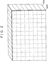
- Fig. 2 is a perspective plan view showing the arrangement of the multi-display large screen display apparatus having a plurality of projection display devices 700 arrayed both longitudinally and laterally in a matrix layout. Images are displayed on the whole screen 600 of each of the projection display devices 700 which are arranged without a seam, thereby forming one large-size display screen without non-display areas.
- a large-size screen projection display apparatus approximately equivalent to the size of a high definition television set, having the size of 240 inches and 960 x 1700 pixels by arranging the projection display devices 700 into a matrix layout composed of 30 displays in a column, and 53 displays in a row. Further, according to the first embodiment of this invention, since the projection magnification factor is selected as low as three times, a thin type large-size screen display apparatus can be produced because of the reduction in projection distance.
- the screen brightness will be one ninth of the brightness of the light bulb in the case where the projection magnification factor is selected as 3 times, and the screen brightness will be one sixteenth of the brightness of the light bulb in the case where the projection magnification factor is selected as 4 times.
- the projection magnification factor is usually selected to 10 times, the brightness drops to as low as one hundredth of the brightness of the light bulb.
- optical image forming section has been described by the use of a three-plate liquid crystal light bulb system, it may be appreciated that the same advantage may be obtained by the use of a single-plate light bulb having a color filter provided on a single liquid crystal cell. Moreover, as shown in Fig. 3, similar results may be produced by the use of the projection CRT 501 in the optical image forming section.
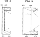
- a means for creating optical images projected from the optical image forming section on the entire screen surface has been disclosed in the form of the concave transparent plate 602, as can be seen from Fig. 4, similar results may be secured by the use of a projection screen 600 to mounted to the housing 505 and being composed of the diffusing surface 601 having the same configuration and provided on the viewing side, and a fresnel lens 603 capable of producing similar results as produced by the concave lens provided on the incident side, both being attached together.
- the projection screen 600 may be alternatively replaced by a screen consisting of the diffusing surface 601 provided on the viewing side and a transparent plate 604 provided on the light entrance side, both attached together.
- the projection screen may be constituted by the combination of the diffusing surface 601 and a distributed-refraction plate 605 attached together.
- the distributed-refraction plate 605 is such a plate wherein the refractive index is least at the center and increases progressively in proportion to the square of a distance (x) from the center to the corners, and the plate may be manufactured by the use of the diffusion polymerization method of plastic having different refractive indices.
Landscapes
- Engineering & Computer Science (AREA)
- Multimedia (AREA)
- Signal Processing (AREA)
- Projection Apparatus (AREA)
- Transforming Electric Information Into Light Information (AREA)
- Devices For Indicating Variable Information By Combining Individual Elements (AREA)
Applications Claiming Priority (2)
| Application Number | Priority Date | Filing Date | Title |
|---|---|---|---|
| JP207289/90 | 1990-08-03 | ||
| JP2207289A JP2794915B2 (ja) | 1990-08-03 | 1990-08-03 | 大画面表示装置 |
Publications (3)
| Publication Number | Publication Date |
|---|---|
| EP0471478A2 true EP0471478A2 (fr) | 1992-02-19 |
| EP0471478A3 EP0471478A3 (en) | 1993-02-24 |
| EP0471478B1 EP0471478B1 (fr) | 1996-04-17 |
Family
ID=16537332
Family Applications (1)
| Application Number | Title | Priority Date | Filing Date |
|---|---|---|---|
| EP91307066A Expired - Lifetime EP0471478B1 (fr) | 1990-08-03 | 1991-08-01 | Appareil d'affichage à grand écran |
Country Status (3)
| Country | Link |
|---|---|
| EP (1) | EP0471478B1 (fr) |
| JP (1) | JP2794915B2 (fr) |
| DE (1) | DE69118776T2 (fr) |
Cited By (4)
| Publication number | Priority date | Publication date | Assignee | Title |
|---|---|---|---|---|
| EP0777389A3 (fr) * | 1995-12-08 | 1997-11-19 | Mitsubishi Denki Kabushiki Kaisha | Système modulaire d'affichage d'image |
| WO1998010322A1 (fr) * | 1996-09-05 | 1998-03-12 | Holakovszky Laszlo | Lunettes stereoscopiques de presentation, particulierement d'images de tv |
| US5897192A (en) * | 1994-04-18 | 1999-04-27 | Seufert; Heinz | Rear projection module |
| CN107850828A (zh) * | 2015-06-30 | 2018-03-27 | 华为技术有限公司 | 一种投影系统 |
Families Citing this family (4)
| Publication number | Priority date | Publication date | Assignee | Title |
|---|---|---|---|---|
| US20140226133A1 (en) * | 2011-09-27 | 2014-08-14 | Nec Corporation | Multiprojection system |
| JP2016009129A (ja) * | 2014-06-25 | 2016-01-18 | シャープ株式会社 | 画像表示装置 |
| JP6914208B2 (ja) * | 2018-01-25 | 2021-08-04 | 三菱プレシジョン株式会社 | 表示装置 |
| JP6925766B2 (ja) * | 2019-08-29 | 2021-08-25 | 株式会社ユニバーサルエンターテインメント | 遊技機 |
Family Cites Families (5)
| Publication number | Priority date | Publication date | Assignee | Title |
|---|---|---|---|---|
| NL8501424A (nl) * | 1985-05-17 | 1986-12-16 | Philips Nv | Optisch beeldvergrotend element, informatie-weergeefeenheid bevattende een dergelijk element en informatie-weergeefpaneel bevattende een aantal van dergelijke eenheden. |
| US4866530A (en) * | 1988-02-22 | 1989-09-12 | Kalua Kevin A | Multiple screen, modular video display projection system |
| JPH0787561B2 (ja) * | 1988-03-08 | 1995-09-20 | パイオニア株式会社 | プロジェクションテレビユニット及びマルチプロジェクションテレビの連結部材 |
| GB2236447A (en) * | 1989-09-05 | 1991-04-03 | K C Tung | TV wall structure |
| JPH03181935A (ja) * | 1989-12-12 | 1991-08-07 | Dainippon Printing Co Ltd | フレネルレンズシートの接合構造と接合方法 |
-
1990
- 1990-08-03 JP JP2207289A patent/JP2794915B2/ja not_active Expired - Fee Related
-
1991
- 1991-08-01 DE DE69118776T patent/DE69118776T2/de not_active Expired - Fee Related
- 1991-08-01 EP EP91307066A patent/EP0471478B1/fr not_active Expired - Lifetime
Cited By (7)
| Publication number | Priority date | Publication date | Assignee | Title |
|---|---|---|---|---|
| US5897192A (en) * | 1994-04-18 | 1999-04-27 | Seufert; Heinz | Rear projection module |
| EP0777389A3 (fr) * | 1995-12-08 | 1997-11-19 | Mitsubishi Denki Kabushiki Kaisha | Système modulaire d'affichage d'image |
| WO1998010322A1 (fr) * | 1996-09-05 | 1998-03-12 | Holakovszky Laszlo | Lunettes stereoscopiques de presentation, particulierement d'images de tv |
| CN107850828A (zh) * | 2015-06-30 | 2018-03-27 | 华为技术有限公司 | 一种投影系统 |
| EP3301510A4 (fr) * | 2015-06-30 | 2018-07-04 | Huawei Technologies Co., Ltd. | Système de projection |
| US10261399B2 (en) | 2015-06-30 | 2019-04-16 | Huawei Technologies Co., Ltd. | Projection system |
| CN107850828B (zh) * | 2015-06-30 | 2020-10-09 | 华为技术有限公司 | 一种投影系统 |
Also Published As
| Publication number | Publication date |
|---|---|
| DE69118776T2 (de) | 1996-09-26 |
| EP0471478B1 (fr) | 1996-04-17 |
| DE69118776D1 (de) | 1996-05-23 |
| JPH0493828A (ja) | 1992-03-26 |
| JP2794915B2 (ja) | 1998-09-10 |
| EP0471478A3 (en) | 1993-02-24 |
Similar Documents
| Publication | Publication Date | Title |
|---|---|---|
| US5250967A (en) | Liquid crystal projector | |
| US5029986A (en) | Electro-optical color display device and projection apparatus | |
| US4431266A (en) | Optical refractor for diffusing light | |
| US5675435A (en) | Rear projection image display device | |
| US7102820B2 (en) | Flat valley fresnel lens for a display device | |
| US6771419B1 (en) | Rear projection type image display unit | |
| US6400505B1 (en) | Rear projection image display apparatus including light exit surface configured to reduce noise | |
| US5803567A (en) | Protection-type display device | |
| EP0471478A2 (fr) | Appareil d'affichage à grand écran | |
| JP2974099B2 (ja) | 透過型液晶パネル及び投写形液晶表示装置 | |
| US5264941A (en) | Large screen display apparatus utilizing a transparent plate to display an image over an entire surface of a diffusing surface | |
| JP2000075259A (ja) | 液晶装置及びこれを用いた投写型表示装置 | |
| JP3499276B2 (ja) | 透過型スクリーン | |
| JPS6332528A (ja) | 透過型スクリ−ン | |
| JPH03253819A (ja) | 液晶デイスプレイ | |
| JPH05346566A (ja) | 投影型カラー画像表示装置 | |
| KR100235299B1 (ko) | 액정 프로젝터 | |
| JPH02275933A (ja) | 液晶プロジェクタ | |
| JP3797888B2 (ja) | 透過型スクリーン及びそれを用いた投射型画像表示装置 | |
| JPH0740997Y2 (ja) | 透過型スクリーン | |
| JPH0345987A (ja) | 背面投射型表示装置 | |
| JPH0740996Y2 (ja) | 透過型スクリーン | |
| JPH0521073Y2 (fr) | ||
| JPH0296737A (ja) | 背面投射型スクリーン及び背面投射型表示装置 | |
| JPH06175229A (ja) | 透過形スクリーン |
Legal Events
| Date | Code | Title | Description |
|---|---|---|---|
| PUAI | Public reference made under article 153(3) epc to a published international application that has entered the european phase |
Free format text: ORIGINAL CODE: 0009012 |
|
| AK | Designated contracting states |
Kind code of ref document: A2 Designated state(s): DE FR GB |
|
| PUAL | Search report despatched |
Free format text: ORIGINAL CODE: 0009013 |
|
| AK | Designated contracting states |
Kind code of ref document: A3 Designated state(s): DE FR GB |
|
| 17P | Request for examination filed |
Effective date: 19930823 |
|
| 17Q | First examination report despatched |
Effective date: 19950824 |
|
| GRAH | Despatch of communication of intention to grant a patent |
Free format text: ORIGINAL CODE: EPIDOS IGRA |
|
| GRAA | (expected) grant |
Free format text: ORIGINAL CODE: 0009210 |
|
| AK | Designated contracting states |
Kind code of ref document: B1 Designated state(s): DE FR GB |
|
| REF | Corresponds to: |
Ref document number: 69118776 Country of ref document: DE Date of ref document: 19960523 |
|
| ET | Fr: translation filed | ||
| PLBE | No opposition filed within time limit |
Free format text: ORIGINAL CODE: 0009261 |
|
| STAA | Information on the status of an ep patent application or granted ep patent |
Free format text: STATUS: NO OPPOSITION FILED WITHIN TIME LIMIT |
|
| 26N | No opposition filed | ||
| REG | Reference to a national code |
Ref country code: GB Ref legal event code: 746 Effective date: 20000126 |
|
| REG | Reference to a national code |
Ref country code: FR Ref legal event code: D6 |
|
| REG | Reference to a national code |
Ref country code: GB Ref legal event code: IF02 |
|
| PGFP | Annual fee paid to national office [announced via postgrant information from national office to epo] |
Ref country code: GB Payment date: 20030730 Year of fee payment: 13 |
|
| PG25 | Lapsed in a contracting state [announced via postgrant information from national office to epo] |
Ref country code: GB Free format text: LAPSE BECAUSE OF NON-PAYMENT OF DUE FEES Effective date: 20040801 |
|
| GBPC | Gb: european patent ceased through non-payment of renewal fee |
Effective date: 20040801 |
|
| PGFP | Annual fee paid to national office [announced via postgrant information from national office to epo] |
Ref country code: DE Payment date: 20050728 Year of fee payment: 15 |
|
| PGFP | Annual fee paid to national office [announced via postgrant information from national office to epo] |
Ref country code: FR Payment date: 20050809 Year of fee payment: 15 |
|
| PG25 | Lapsed in a contracting state [announced via postgrant information from national office to epo] |
Ref country code: DE Free format text: LAPSE BECAUSE OF NON-PAYMENT OF DUE FEES Effective date: 20070301 |
|
| REG | Reference to a national code |
Ref country code: FR Ref legal event code: ST Effective date: 20070430 |
|
| PG25 | Lapsed in a contracting state [announced via postgrant information from national office to epo] |
Ref country code: FR Free format text: LAPSE BECAUSE OF NON-PAYMENT OF DUE FEES Effective date: 20060831 |