EP0472094A1 - Fertiger für Strassendecken mit einer um ein Scharnier schwingenden Unterplatte, welches die Platte mit einer tragenden Struktur verbindet - Google Patents
Fertiger für Strassendecken mit einer um ein Scharnier schwingenden Unterplatte, welches die Platte mit einer tragenden Struktur verbindet Download PDFInfo
- Publication number
- EP0472094A1 EP0472094A1 EP91113566A EP91113566A EP0472094A1 EP 0472094 A1 EP0472094 A1 EP 0472094A1 EP 91113566 A EP91113566 A EP 91113566A EP 91113566 A EP91113566 A EP 91113566A EP 0472094 A1 EP0472094 A1 EP 0472094A1
- Authority
- EP
- European Patent Office
- Prior art keywords
- plate
- road
- vibrations
- paver
- connecting means
- Prior art date
- Legal status (The legal status is an assumption and is not a legal conclusion. Google has not performed a legal analysis and makes no representation as to the accuracy of the status listed.)
- Granted
Links
- 239000000463 material Substances 0.000 claims abstract description 12
- 230000001681 protective effect Effects 0.000 claims abstract description 8
- 238000000034 method Methods 0.000 claims abstract description 7
- 230000008569 process Effects 0.000 claims abstract description 6
- 239000002245 particle Substances 0.000 claims abstract description 4
- 238000009499 grossing Methods 0.000 claims description 2
- 238000013016 damping Methods 0.000 abstract description 2
- 210000000078 claw Anatomy 0.000 description 6
- 230000000694 effects Effects 0.000 description 4
- 238000005096 rolling process Methods 0.000 description 2
- 229910000679 solder Inorganic materials 0.000 description 2
- 230000009471 action Effects 0.000 description 1
- 230000008859 change Effects 0.000 description 1
- 230000003247 decreasing effect Effects 0.000 description 1
- 239000004744 fabric Substances 0.000 description 1
- 238000012423 maintenance Methods 0.000 description 1
- 238000004321 preservation Methods 0.000 description 1
- 230000000750 progressive effect Effects 0.000 description 1
- 230000009467 reduction Effects 0.000 description 1
Images


Classifications
-
- E—FIXED CONSTRUCTIONS
- E01—CONSTRUCTION OF ROADS, RAILWAYS, OR BRIDGES
- E01C—CONSTRUCTION OF, OR SURFACES FOR, ROADS, SPORTS GROUNDS, OR THE LIKE; MACHINES OR AUXILIARY TOOLS FOR CONSTRUCTION OR REPAIR
- E01C19/00—Machines, tools or auxiliary devices for preparing or distributing paving materials, for working the placed materials, or for forming, consolidating, or finishing the paving
- E01C19/22—Machines, tools or auxiliary devices for preparing or distributing paving materials, for working the placed materials, or for forming, consolidating, or finishing the paving for consolidating or finishing laid-down unset materials
- E01C19/30—Tamping or vibrating apparatus other than rollers ; Devices for ramming individual paving elements
- E01C19/34—Power-driven rammers or tampers, e.g. air-hammer impacted shoes for ramming stone-sett paving; Hand-actuated ramming or tamping machines, e.g. tampers with manually hoisted dropping weight
- E01C19/40—Power-driven rammers or tampers, e.g. air-hammer impacted shoes for ramming stone-sett paving; Hand-actuated ramming or tamping machines, e.g. tampers with manually hoisted dropping weight adapted to impart a smooth finish to the paving, e.g. tamping or vibrating finishers
- E01C19/407—Power-driven rammers or tampers, e.g. air-hammer impacted shoes for ramming stone-sett paving; Hand-actuated ramming or tamping machines, e.g. tampers with manually hoisted dropping weight adapted to impart a smooth finish to the paving, e.g. tamping or vibrating finishers with elements or parts partly or fully immersed in or penetrating into the material to act thereon, e.g. immersed vibrators or vibrating parts, kneading tampers, spaders
Definitions
- the present invention relates to a paver for road surfaces, which is suitable to be installed in the front parts of a road working machine; the paver may have a fixed or a variable dimension, the road working machine causing the paver to move to create a pavement of a predetermined thickness.
- the length of a paver with an unchangeable dimension can only be changed by using extensions;
- a variable size paver consists of a fixed structure and one or more structures that slide on the fixed structure to change the length of the same paver.
- Single-direction or multi-directional vibrators can be installed on the conventional finished products, which vibrate a plate of the paver so that the road surface is leveled compactly and smoothly.
- the vibrating devices In order to maintain a wave movement, the vibration range of which is adapted to the use of the paver, the vibrating devices should have a power which is suitable for the mass of the paver to be vibrated.
- the invention has for its object to allow a single structure of the paver to vibrate in order to reduce the power requirement, although it achieves leveling effects that are comparable to the leveling effects of conventional pavers, which reduce a very large power requirement, or to achieve large leveling effects , although the same power requirement of conventional pavers is reduced.
- FIG. 1 shows a front view of a paver according to the invention, in which a vibrating device 1 equipped with an external center mass 30 is kinematically connected to a motor 2 such that the motor 2 can rotate the vibrating device 1.
- FIG. 2 shows a section of the paver shown in FIG. 1 with the solder plane A-A, in these figures a supporting upper structure 3 is shown, which carries a plate-shaped lower structure 7.
- the plate 7 is connected to the upper structure 3 by a hinge 6 arranged in the front parts of the paver and by two pairs of springs 8 and 9 located in the side ends of the paver, a pair of bolts 10 being provided for compressing the springs 8 and 9.
- the supporting structure 3 is connected to the road working machine, not shown, by conventional means, not shown;
- conventional links (not shown) for controlling the paver with respect to the road working machine are provided in order to make a predetermined thickness X (FIG. 2) out of covering material, the covering material on the street level being in piles in front of the street working machine.
- a protective member 5 is in front of the hinge 6 between the structure 3 and the plate 7 to prevent the particles of covering material from entering the hinge 6 while the road working machine is moving in the C direction.
- the protective member 5 extends at least over the entire length of the hinge 6.
- the paver driven by the road working machine moves in the direction of arrow C;
- the structure 3 installed in the roadworking machine tears the plate 7 in the same direction C, the plate 7 with the structure 3 being bound by the hinge 6.
- the plate 7 is shaken by the vibrator 1, which ver kinematically with the motor 2 is bound; the vibrating plate 7 compresses the covering material to maintain a thickness X; this process makes the cover fabric smooth.
- the plate 7 rotates around the hinge 6 in alternating movements under the action of the vibrating device 1; this has an external center mass 30, which tensions the plate 7 in four directions D, E, F, G. Nevertheless, the plate 7 connected to the structure 3 by the hinge 6 can only swing in directions E and D. This results in an alternating movement of the plate in directions E and D, which are almost vertical due to the limited width of the vibrations. It can be proved mathematically that the vibrations of the plate 7 occur practically in vertical directions if the width of the vibrations is limited to an angle of almost fifteen degrees, the arc of which can be compared with the sine.
- the width of the arc described by the plate 7 depends on the distance of the points belonging to the plate 7 from the hinge 6; in the part of the plate 7 which acts on the road surface, the widths of the arches are sufficient to produce a uniform and progressive compactness of the thickness X of the covering material 4 due to the movement of the plate 7 in the direction C.
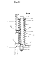
- the pairs of springs 8 and 9 are arranged, as shown in Figure 3.
- first claw 14 fastened to the structure 3
- the claw 14 being provided with a first through hole 15 for the bolt 10.
- a second claw 16 fastened to the plate 7 is provided with a second through hole 17 for the bolt 10.
- the spring 9 is arranged between a support plane 20 provided in the claw 15 and a support plane 21 which is located in one side 22 of a bush 23: the head of the bolt 10 is supported on a second side 24 opposite the first side 22.
- a screw nut 25 is supported on a plane 26 of the claw 16 for adjusting the tension of the spring 8, which determines the tension of the spring 9.
- the width of the vibrations of the plate 7 depends on the tension of the spring 9 in an inversely proportional manner.
- the spring 9 transfers the vibrations to the structure 3; nevertheless, the vibrations are damped by the elasticity of the spring 9 in order not to tension the structure 3, which is connected to the road working machine.
- the claw 14 is constructed so that it can withstand the muzzle of the material from which it is made.
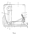
- FIG. 4 shows the paver equipped with a device for starting the stumping process of the road surface.
- This device consists of an outer-center rotor 27 and a stump 11 which is connected to the rotor 27 by a conventional connecting member 28.
- the rotor 27 drives the stump 11 alternately up and down to the beginning of the smoothing process of the road surface, which is processed by the plate 7.
- a protective member 12 is arranged in front of the hinge 6 in the direction C of the movement of the road working machine to prevent the particles of covering material from entering the hinge 6, the protective member 12 extending at least over the entire length of the hinge 6.
- the hinge 6 is an elastic hinge that combines the functions of binding with a degree of freedom between the structures 3 and 7 and of elastic connection between the same structures.
- a single spring 9 is used for the elastic connection of the structures 3 and 7, the spring 9 being equipped with a nut screw 10 for adjusting its tension.
Landscapes
- Engineering & Computer Science (AREA)
- Architecture (AREA)
- Civil Engineering (AREA)
- Structural Engineering (AREA)
- Road Paving Machines (AREA)
- Vibration Prevention Devices (AREA)
- Road Signs Or Road Markings (AREA)
Abstract
Description
- Die vorliegende Erfindung betrifft einen Fertiger für Strassendecken, der geeignet ist, im Vorderteile einer Strassenarbeitsmaschine eingebaut zu sein; der Fertiger kann ein unveränderliches oder ein veränderliches Maß aufweisen, wobei die Strassenarbeitsmaschine für die Bewegung des Fertigers sorgt, um eine Strassendecke mit einer vorbestimmten Dicke auszufertigen. Die Lange eines Fertigers mit unveränderlichem Maß kann nur durch die Verwendung von Verlängerungen verändert werden; ein Fertiger mit veränderlichem Maß besteht aus einer festen Struktur und aus einer oder mehreren Strukturen, die sich auf der festen Struktur gleiten lassen, um die Lange desselben Fertigers zu verändern.
- Auf den herkömmlichen Fertigem lassen sich einsinnige oder mehrsinnige Rüttelvorrichtungen einbauen, die für die Schwingungen einer Platte des Fertigers sorgen, damit die Strassendecke kompakt und glatt geebnet wird. Zur Erhaltung einer Wellenbewegung, deren Schwingungsweite an die Verwendung des Fertigers angepasst ist, sollen die Rüttelvorrichtungen eine für die zu schwingende Masse des Fertigers geeignete Leistung haben.
- Der Erfindung liegt die Aufgabe zugrunde eine einzige Struktur des Fertigers schwingen zu lassen, um den Leistungsbedarf zu vermindern, obgleich Ebenungswirkungen dadurch erreicht werden, die vergleichbar zu den Ebenungswirkungen der herkömmlichen Fertiger sind, die einen sehr grossen Leistungsbedarf abnehmen, oder um grosse Ebenungswirkungen zu erreichen, obgleich derselbe Leistungsbedarf der herkömmlichen Fertiger dadurch abgenommen wird.
- Außerdem werden die folgenden Aufgaben durch die Verwendung der Erfindung gelöst
- 1- Die Dämpfung der auf die tragende Struktur übertragenen Schwingungen, um eine gute Arbeitszustand für den Bediener zu erhalten;
- 2- Die Erhaltung einer richtigen Bemessung der tragenden Struktur in Bezug auf die sehr beschänkten Schwingungen;
- 3- Das Übertagen einer fortlaufenden Schwingung auf den auf der Strassendecke gelegenen Deckungsstoff zur Erhaltung einer richtigen Sclußkompaktheit;
- 4- Die Erhaltung derselben Ebenungswirkungen, die durch einen mit einer einsinnigen Rüttelvorrichtung augestatteten Fertiger erhalten werden, durch die Verwendung einer in dem erfindungsgemäßen Fertiger eingebauten mehrsinnigen Rüttelvorrichtung, wobei die einsinnige Rüttelvorrichtung denselben Leistungsbedarf abnimmt;
- 5- Die Verminderung des darauffolgenden Glattwalzens durch Strassenwalze wegen der durch den erfindungsgemäßen Fertiger erreichten Kompaktheitsgrad.
- Weitere Vorteile, Einzelheiten und erfindungswesentliche Merkmale ergeben sich aus der nachfolgenden Beschreibung eines Ausführungsbeispiels des Fertigers gemäß der Erfindung, unter bezugnahme auf die beigefügten Zeichnungen. Dabei zeigt im einzelnen:
- Fig.1 eine Ansicht von vorne eines erfindungsgemäßen Fertigers;
- Fig.2 einen Schnitt des in der Fig.1 dargestellten Fertigers mit den Lotebene A-A;
- Fig.3 einen Bestandteil des Fertigers in einem Schnitt mit einer Ebene B-B;
- Fig.4 einen Vetikalschnitt des erfindungsgemäßen Fertigers zur Dartellung einer Vorrichtung, die das Rammarbeitsverfahren der Strassendecke anfängt.
- Fig.1 stellt eine Ansicht von vorne eines erfindungsgemäßen Fertigers dar, in dem eine mit aussenmittiger Masse 30 ausgestattete Rüttelvorrichtung 1 mit einem Motor 2 so kinematisch verbunden ist, daß der Motor 2 die Rüttelvorrichtung 1 drehen läßt.
- Fig.2 stellt einen Schnitt des in der Fig.1 dargestellten Fertigers mit der Lotebene A-A dar, in diesen Figuren ist eine tragende Oberstruktur 3 dargestellt, welche eine plattenförmige Unterstruktur 7 trägt. Die Platte 7 wird mit der Oberstruktur 3 durch ein im Vorderteile des Fertigers angeordnetes Scharnier 6 und durch zwei in den Seitenenden des Fertigers sich befindliche Paar Feder 8 und 9 verbunden, wobei ein Paar Bolzen 10 zur Zusammendrückung der Feder 8 und 9 vorgesehen sind.
- Die tragende Struktur 3 wird mit der nicht dargestellten Strassenarbeitsmaschine durch nicht dargestellte herkömmliche Mittel verbunden; außerdem sind nicht dargestellte herkömmliche Glieder zur Steuerung des Fertigers in Bezug auf die Strassenarbeitsmaschine vorgesehen, um eine vorbestimmte Dicke X (Fig.2) aus Deckungsstoff auszufertigen, wobei sich der Deckungsstoff auf der Strassenebene haufenweise vor der Strassenarbeitsmaschine befindet.
- Ein Schtutzglied 5 ist vor dem Scharnier 6 zwischen der Struktur 3 und der Platte 7 zur Verhinderung des Eingangs der Teilchen aus Deckungsstoff in das Scharnier 6, während sich die Strassenarbeitsmaschine in der Richtung C bewegt. Das Schtutzglied 5 erstreckt sich am mindest über die ganze Lange des Scharniers 6.
- Der durch die Strassenarbeitsmaschine getriebene Fertiger bewegt sich in der Richtung des Pfeils C;
- die in der Strassenarbeitsmaschine eingebaute Struktur 3 reißt die Platte 7 in derselben Richtung C, wobei die Platte 7 mit der Struktur 3 durch das Scharnier 6 gebunden ist.
- Die Platte 7 wird durch die Rüttelvorrichtung 1 gererüttelt, die mit dem Motor 2 kinematisch verbunden ist; die schwingende Platte 7 verdichtet den Deckungsstoff zur Erhaltung einer Dicke X; durch dieses Verfahren wird der Deckungsstoff glatt gemacht.
- Die Platte 7 dreht sich um das Scharnier 6 in alternierenden Bewegungen unter der Wirkung der Rüttelvorrichtung 1; diese weist eine aussenmittige Masse 30 auf, die die Platte 7 in vier Richtungen D, E, F, G spannt. Trotzdem kann die mit der Struktur 3 durch das Scharnier 6 verbundene Platte 7 nur in den Richtungen E und D schwingen. Daraus entsteht eine alternierende Bewegung der Platte in der Richtungen E und D, die wegen der beschränkten Weite der Schwingungen fast vertikal sind. Es ist matematisch beweisbar, daß die Schwingungen der Platte 7 in vertikalen Richtungen pratisch geschehen, wenn die Weite der Schwingungen in einem Winkel von fast fünfzehn Grad begrenzt ist, dessen Bogen mit dem Sinus vergliechbar ist. Es ist klar, daß die Weite des durch die Platte 7 beschriebenen Bogens vom Abstand der der Platte 7 angehörigen Punkte vom Scharnier 6 abhängt; im Teile der Platte 7 der auf dem Strassenmantel wirkt, sind die Weiten der Bogen genügend, um eine gliechartige und progressive Kompaktheit der Dicke X des Deckungsstoffes 4 infolge der Bewegung der Platte 7 in der Richtung C auszufertigen.
- Die Paare Feder 8 und 9 sind angeordnet, wie das in der Fig.3 dargestellt ist. Für jedes Paar Feder 8 und 9 ist eine mit der Struktur 3 befestigte erste Pratze 14 vorgesehen, wobei die Pratze 14 mit einem ersten durchgehenden Loch 15 für den Bolzen 10 ausgestattet ist. Eine mit der Platte 7 befestigte zweite Pratze 16 ist mit einem zweiten durchgehenden Loch 17 für den Bolzen 10 ausgestattet. Die Feder 9 ist zwischen einer in der Pratze 15 vorgesehenen Auflageebene 20 und einer Auflageebene 21 angeordnet, die sich in einer Seite 22 einer Buchse 23 befindet: der Kopf des Bolzens 10 stützt sich auf einem der ersten Seite 22 entgegensetzenden zweiten Seite 24. Eine Schraubenmutter 25 stützt sich auf einer Ebene 26 der Pratze 16 zur Verstellung der Spannung der Feder 8, die die Spannung der Feder 9 bestimmt.
- Die Weite der Schwingungen der Platte 7 hängt von der Spannung der Feder 9 in ungekehrt proportionaler Weise ab.
- Die Feder 9 übertragen die Schwingungen auf die Struktur 3; trotzdem sind die Schwingungen durch die Elastizität der Feder 9 gedämpft um die Struktur 3 gefährlich nicht zu spannen, die mit der Strassenarbeitsmaschine verbunden ist. Außerdem ist die Pratze 14 so gebaut, daß sie die Ermündung des Stoffes aushaltet, aus dem sie besteht.
- Fig.4 stellt den mit einer Vorrichtung zum Anfang des Stumpfverfahrens der Strassendecke ausgestatteten Fertiger dar.
- Diese Vorrichtung besteht aus einem aussenmittigen Läufer 27 und aus einem Stumpfer 11, der mit dem Läufer 27 durch ein herkömmliches Verbindungsglied 28 verbunden ist. Der Läufer 27 treibt den Stumpfer 11 wechselweise nach oben und nach unten zum Anfang des Glättungsverfahrens der Strassendecke, das durch die Platte 7 abgearbeitet wird.
- Ein Schutzglied 12 ist vor dem Scharnier 6 in der Richtung C der Bewegung der Strassenarbeitsmaschine zur Verhinderung des Eingangs der Teilchen aus Deckungsstoff in das Scharnier 6 angeordnet, wobei sich das Schutzglied 12 am mindest über die ganze Lange des Scharniers 6 erstreckt.
- In einer nicht dargestellten Ausführungsform der Erfindung ist das Scharnier 6 ein elastisches Scharnier, das die Funktionen von Bindung mit einem Freiheitsgrad zwischen den Strukturen 3 und 7 und von elastischer Verbindung zwischen denselben Strukturen vereinigt.
- In einer nicht dargestellten weiteren Ausführungsform wird eine einzige Feder 9 zur elastischen Verbindung der Strukturen 3 und 7, wobei die Feder 9 mit einer Muttelschraube 10 zur Verstellung seiner Spannung ausgestattet ist.
Claims (7)
Applications Claiming Priority (2)
| Application Number | Priority Date | Filing Date | Title |
|---|---|---|---|
| IT04631290A IT1243556B (it) | 1990-08-23 | 1990-08-23 | Ferro da stiro, per distesa di manti stradali, con parte inferiore oscillante attorno ad un asse posto sul ferro da stiro medesimo. |
| IT4631290 | 1990-08-23 |
Publications (2)
| Publication Number | Publication Date |
|---|---|
| EP0472094A1 true EP0472094A1 (de) | 1992-02-26 |
| EP0472094B1 EP0472094B1 (de) | 1995-01-11 |
Family
ID=11258601
Family Applications (1)
| Application Number | Title | Priority Date | Filing Date |
|---|---|---|---|
| EP91113566A Expired - Lifetime EP0472094B1 (de) | 1990-08-23 | 1991-08-13 | Fertiger für Strassendecken mit einer um ein Scharnier schwingenden Unterplatte, welches die Platte mit einer tragenden Struktur verbindet |
Country Status (4)
| Country | Link |
|---|---|
| EP (1) | EP0472094B1 (de) |
| DE (1) | DE59104216D1 (de) |
| ES (1) | ES2069140T3 (de) |
| IT (1) | IT1243556B (de) |
Cited By (2)
| Publication number | Priority date | Publication date | Assignee | Title |
|---|---|---|---|---|
| EP0586886A3 (en) * | 1992-09-09 | 1994-06-01 | Joseph Voegele Ag | Screed for a road paver |
| WO2013067869A1 (zh) * | 2011-11-11 | 2013-05-16 | 中联重科股份有限公司 | 熨平板和摊铺机 |
Citations (4)
| Publication number | Priority date | Publication date | Assignee | Title |
|---|---|---|---|---|
| FR893442A (fr) * | 1942-05-04 | 1944-06-08 | Licentia Gmbh | Appareil pour la construction de revêtements de routes en béton ou autres matériaux de remblai analogues |
| WO1980000160A1 (fr) * | 1978-06-28 | 1980-02-07 | Aebi Ag R | Machines de finition pour route en beton |
| US4313690A (en) * | 1977-12-14 | 1982-02-02 | As Phonix | Asphalt laying machine |
| DE3114049A1 (de) * | 1981-04-07 | 1982-10-14 | Joseph Vögele AG, 6800 Mannheim | Schwarzdeckenfertiger |
-
1990
- 1990-08-23 IT IT04631290A patent/IT1243556B/it active IP Right Grant
-
1991
- 1991-08-13 DE DE59104216T patent/DE59104216D1/de not_active Expired - Lifetime
- 1991-08-13 ES ES91113566T patent/ES2069140T3/es not_active Expired - Lifetime
- 1991-08-13 EP EP91113566A patent/EP0472094B1/de not_active Expired - Lifetime
Patent Citations (4)
| Publication number | Priority date | Publication date | Assignee | Title |
|---|---|---|---|---|
| FR893442A (fr) * | 1942-05-04 | 1944-06-08 | Licentia Gmbh | Appareil pour la construction de revêtements de routes en béton ou autres matériaux de remblai analogues |
| US4313690A (en) * | 1977-12-14 | 1982-02-02 | As Phonix | Asphalt laying machine |
| WO1980000160A1 (fr) * | 1978-06-28 | 1980-02-07 | Aebi Ag R | Machines de finition pour route en beton |
| DE3114049A1 (de) * | 1981-04-07 | 1982-10-14 | Joseph Vögele AG, 6800 Mannheim | Schwarzdeckenfertiger |
Cited By (2)
| Publication number | Priority date | Publication date | Assignee | Title |
|---|---|---|---|---|
| EP0586886A3 (en) * | 1992-09-09 | 1994-06-01 | Joseph Voegele Ag | Screed for a road paver |
| WO2013067869A1 (zh) * | 2011-11-11 | 2013-05-16 | 中联重科股份有限公司 | 熨平板和摊铺机 |
Also Published As
| Publication number | Publication date |
|---|---|
| IT9046312A1 (it) | 1992-02-23 |
| IT1243556B (it) | 1994-06-16 |
| EP0472094B1 (de) | 1995-01-11 |
| DE59104216D1 (de) | 1995-02-23 |
| ES2069140T3 (es) | 1995-05-01 |
| IT9046312A0 (it) | 1990-08-23 |
Similar Documents
| Publication | Publication Date | Title |
|---|---|---|
| EP0155527B1 (de) | Vorrichtung zum Putzen von Griessen | |
| DE3402861C2 (de) | ||
| DE3128349A1 (de) | Lineare abtriebseinheit fuer einen auf einer festen abstuetzung elastisch zu lagernden schwingfoerderer | |
| DE2918935A1 (de) | Schwingfoerderer | |
| DE2136279B2 (de) | Vibratorhalterung | |
| DE2232831A1 (de) | Schwingvorrichtung zur handhabung von material und verfahren zum veraendern der richtung einer schwingkraft | |
| DE19629324C1 (de) | Vibrationsplatte mit Besohlung | |
| EP2910312A1 (de) | Schwinganordnung für einen Rütteltisch oder eine Siebvorrichtung | |
| DE2301653C3 (de) | Straßenbehandlungsgerät zur Verbesserung der Griffigkeit eines Strafien- | |
| DE2503845A1 (de) | Verfahren und vorrichtung zum schwingpolieren von einzelnen materialstuecken, insbesondere schmucksteinen in einem schwingenden behaelter | |
| DE3500173A1 (de) | Giessformvorrichtung | |
| DE3921349C2 (de) | ||
| EP0943037B1 (de) | Bandage für walzen zur bodenverdichtung | |
| DE1959939A1 (de) | Vibrationseinrichtung zur Materialbehandlung | |
| DE3512215A1 (de) | Siebmaschine mit einem flexiblen siebbelag | |
| DE3741966C2 (de) | ||
| EP1899245B1 (de) | Linear-vibrationsförderer | |
| EP0358632B1 (de) | Siebvorrichtung | |
| EP0472094A1 (de) | Fertiger für Strassendecken mit einer um ein Scharnier schwingenden Unterplatte, welches die Platte mit einer tragenden Struktur verbindet | |
| EP0374428B1 (de) | Verdichtungsbohle für einen Strassenfertiger | |
| EP0586886B1 (de) | Einbaubohle für einen Strassenfertiger | |
| EP0218575A2 (de) | Siebvorrichtung | |
| DE3035890C2 (de) | Fahrbare Gleisstopfmaschine | |
| DE3507073C2 (de) | ||
| DE2204022B2 (de) | Abziehvorrichtung für Betonoberflächen od.dgl |
Legal Events
| Date | Code | Title | Description |
|---|---|---|---|
| PUAI | Public reference made under article 153(3) epc to a published international application that has entered the european phase |
Free format text: ORIGINAL CODE: 0009012 |
|
| AK | Designated contracting states |
Kind code of ref document: A1 Designated state(s): DE ES FR GB |
|
| 17P | Request for examination filed |
Effective date: 19920818 |
|
| RAP1 | Party data changed (applicant data changed or rights of an application transferred) |
Owner name: JOSEPH VOEGELE AG |
|
| 17Q | First examination report despatched |
Effective date: 19930910 |
|
| GRAA | (expected) grant |
Free format text: ORIGINAL CODE: 0009210 |
|
| AK | Designated contracting states |
Kind code of ref document: B1 Designated state(s): DE ES FR GB |
|
| REF | Corresponds to: |
Ref document number: 59104216 Country of ref document: DE Date of ref document: 19950223 |
|
| GBT | Gb: translation of ep patent filed (gb section 77(6)(a)/1977) |
Effective date: 19950127 |
|
| ET | Fr: translation filed | ||
| REG | Reference to a national code |
Ref country code: ES Ref legal event code: FG2A Ref document number: 2069140 Country of ref document: ES Kind code of ref document: T3 |
|
| PLBE | No opposition filed within time limit |
Free format text: ORIGINAL CODE: 0009261 |
|
| STAA | Information on the status of an ep patent application or granted ep patent |
Free format text: STATUS: NO OPPOSITION FILED WITHIN TIME LIMIT |
|
| 26N | No opposition filed | ||
| PGFP | Annual fee paid to national office [announced via postgrant information from national office to epo] |
Ref country code: FR Payment date: 20000816 Year of fee payment: 10 Ref country code: ES Payment date: 20000816 Year of fee payment: 10 |
|
| PG25 | Lapsed in a contracting state [announced via postgrant information from national office to epo] |
Ref country code: ES Free format text: LAPSE BECAUSE OF NON-PAYMENT OF DUE FEES Effective date: 20010814 |
|
| REG | Reference to a national code |
Ref country code: GB Ref legal event code: IF02 |
|
| PG25 | Lapsed in a contracting state [announced via postgrant information from national office to epo] |
Ref country code: FR Free format text: LAPSE BECAUSE OF NON-PAYMENT OF DUE FEES Effective date: 20020430 |
|
| REG | Reference to a national code |
Ref country code: FR Ref legal event code: ST |
|
| REG | Reference to a national code |
Ref country code: ES Ref legal event code: FD2A Effective date: 20020911 |
|
| PGFP | Annual fee paid to national office [announced via postgrant information from national office to epo] |
Ref country code: GB Payment date: 20050808 Year of fee payment: 15 |
|
| GBPC | Gb: european patent ceased through non-payment of renewal fee |
Effective date: 20060813 |
|
| PG25 | Lapsed in a contracting state [announced via postgrant information from national office to epo] |
Ref country code: GB Free format text: LAPSE BECAUSE OF NON-PAYMENT OF DUE FEES Effective date: 20060813 |
|
| PGFP | Annual fee paid to national office [announced via postgrant information from national office to epo] |
Ref country code: DE Payment date: 20100929 Year of fee payment: 20 |
|
| REG | Reference to a national code |
Ref country code: DE Ref legal event code: R071 Ref document number: 59104216 Country of ref document: DE |
|
| REG | Reference to a national code |
Ref country code: DE Ref legal event code: R071 Ref document number: 59104216 Country of ref document: DE |
|
| REG | Reference to a national code |
Ref country code: DE Ref legal event code: R082 Ref document number: 59104216 Country of ref document: DE Representative=s name: GRUENECKER, KINKELDEY, STOCKMAIR & SCHWANHAEUS, DE |
|
| REG | Reference to a national code |
Ref country code: DE Ref legal event code: R081 Ref document number: 59104216 Country of ref document: DE Owner name: JOSEPH VOEGELE AG, DE Free format text: FORMER OWNER: JOSEPH VOEGELE AG, 68163 MANNHEIM, DE Effective date: 20120217 Ref country code: DE Ref legal event code: R082 Ref document number: 59104216 Country of ref document: DE Representative=s name: GRUENECKER, KINKELDEY, STOCKMAIR & SCHWANHAEUS, DE Effective date: 20120217 Ref country code: DE Ref legal event code: R082 Ref document number: 59104216 Country of ref document: DE Representative=s name: GRUENECKER PATENT- UND RECHTSANWAELTE PARTG MB, DE Effective date: 20120217 |
|
| PG25 | Lapsed in a contracting state [announced via postgrant information from national office to epo] |
Ref country code: DE Free format text: LAPSE BECAUSE OF EXPIRATION OF PROTECTION Effective date: 20110814 |