EP0472094A1 - Finisseuse pour revêtements routiers avec plaque inférieure oscillante autour d'une charnière liant cette plaque à une structure portante - Google Patents
Finisseuse pour revêtements routiers avec plaque inférieure oscillante autour d'une charnière liant cette plaque à une structure portante Download PDFInfo
- Publication number
- EP0472094A1 EP0472094A1 EP91113566A EP91113566A EP0472094A1 EP 0472094 A1 EP0472094 A1 EP 0472094A1 EP 91113566 A EP91113566 A EP 91113566A EP 91113566 A EP91113566 A EP 91113566A EP 0472094 A1 EP0472094 A1 EP 0472094A1
- Authority
- EP
- European Patent Office
- Prior art keywords
- plate
- road
- vibrations
- paver
- connecting means
- Prior art date
- Legal status (The legal status is an assumption and is not a legal conclusion. Google has not performed a legal analysis and makes no representation as to the accuracy of the status listed.)
- Granted
Links
- 239000000463 material Substances 0.000 claims abstract description 12
- 230000001681 protective effect Effects 0.000 claims abstract description 8
- 238000000034 method Methods 0.000 claims abstract description 7
- 230000008569 process Effects 0.000 claims abstract description 6
- 239000002245 particle Substances 0.000 claims abstract description 4
- 238000009499 grossing Methods 0.000 claims description 2
- 238000013016 damping Methods 0.000 abstract description 2
- 210000000078 claw Anatomy 0.000 description 6
- 230000000694 effects Effects 0.000 description 4
- 238000005096 rolling process Methods 0.000 description 2
- 229910000679 solder Inorganic materials 0.000 description 2
- 230000009471 action Effects 0.000 description 1
- 230000008859 change Effects 0.000 description 1
- 230000003247 decreasing effect Effects 0.000 description 1
- 239000004744 fabric Substances 0.000 description 1
- 238000012423 maintenance Methods 0.000 description 1
- 238000004321 preservation Methods 0.000 description 1
- 230000000750 progressive effect Effects 0.000 description 1
- 230000009467 reduction Effects 0.000 description 1
Images


Classifications
-
- E—FIXED CONSTRUCTIONS
- E01—CONSTRUCTION OF ROADS, RAILWAYS, OR BRIDGES
- E01C—CONSTRUCTION OF, OR SURFACES FOR, ROADS, SPORTS GROUNDS, OR THE LIKE; MACHINES OR AUXILIARY TOOLS FOR CONSTRUCTION OR REPAIR
- E01C19/00—Machines, tools or auxiliary devices for preparing or distributing paving materials, for working the placed materials, or for forming, consolidating, or finishing the paving
- E01C19/22—Machines, tools or auxiliary devices for preparing or distributing paving materials, for working the placed materials, or for forming, consolidating, or finishing the paving for consolidating or finishing laid-down unset materials
- E01C19/30—Tamping or vibrating apparatus other than rollers ; Devices for ramming individual paving elements
- E01C19/34—Power-driven rammers or tampers, e.g. air-hammer impacted shoes for ramming stone-sett paving; Hand-actuated ramming or tamping machines, e.g. tampers with manually hoisted dropping weight
- E01C19/40—Power-driven rammers or tampers, e.g. air-hammer impacted shoes for ramming stone-sett paving; Hand-actuated ramming or tamping machines, e.g. tampers with manually hoisted dropping weight adapted to impart a smooth finish to the paving, e.g. tamping or vibrating finishers
- E01C19/407—Power-driven rammers or tampers, e.g. air-hammer impacted shoes for ramming stone-sett paving; Hand-actuated ramming or tamping machines, e.g. tampers with manually hoisted dropping weight adapted to impart a smooth finish to the paving, e.g. tamping or vibrating finishers with elements or parts partly or fully immersed in or penetrating into the material to act thereon, e.g. immersed vibrators or vibrating parts, kneading tampers, spaders
Definitions
- the present invention relates to a paver for road surfaces, which is suitable to be installed in the front parts of a road working machine; the paver may have a fixed or a variable dimension, the road working machine causing the paver to move to create a pavement of a predetermined thickness.
- the length of a paver with an unchangeable dimension can only be changed by using extensions;
- a variable size paver consists of a fixed structure and one or more structures that slide on the fixed structure to change the length of the same paver.
- Single-direction or multi-directional vibrators can be installed on the conventional finished products, which vibrate a plate of the paver so that the road surface is leveled compactly and smoothly.
- the vibrating devices In order to maintain a wave movement, the vibration range of which is adapted to the use of the paver, the vibrating devices should have a power which is suitable for the mass of the paver to be vibrated.
- the invention has for its object to allow a single structure of the paver to vibrate in order to reduce the power requirement, although it achieves leveling effects that are comparable to the leveling effects of conventional pavers, which reduce a very large power requirement, or to achieve large leveling effects , although the same power requirement of conventional pavers is reduced.
- FIG. 1 shows a front view of a paver according to the invention, in which a vibrating device 1 equipped with an external center mass 30 is kinematically connected to a motor 2 such that the motor 2 can rotate the vibrating device 1.
- FIG. 2 shows a section of the paver shown in FIG. 1 with the solder plane A-A, in these figures a supporting upper structure 3 is shown, which carries a plate-shaped lower structure 7.
- the plate 7 is connected to the upper structure 3 by a hinge 6 arranged in the front parts of the paver and by two pairs of springs 8 and 9 located in the side ends of the paver, a pair of bolts 10 being provided for compressing the springs 8 and 9.
- the supporting structure 3 is connected to the road working machine, not shown, by conventional means, not shown;
- conventional links (not shown) for controlling the paver with respect to the road working machine are provided in order to make a predetermined thickness X (FIG. 2) out of covering material, the covering material on the street level being in piles in front of the street working machine.
- a protective member 5 is in front of the hinge 6 between the structure 3 and the plate 7 to prevent the particles of covering material from entering the hinge 6 while the road working machine is moving in the C direction.
- the protective member 5 extends at least over the entire length of the hinge 6.
- the paver driven by the road working machine moves in the direction of arrow C;
- the structure 3 installed in the roadworking machine tears the plate 7 in the same direction C, the plate 7 with the structure 3 being bound by the hinge 6.
- the plate 7 is shaken by the vibrator 1, which ver kinematically with the motor 2 is bound; the vibrating plate 7 compresses the covering material to maintain a thickness X; this process makes the cover fabric smooth.
- the plate 7 rotates around the hinge 6 in alternating movements under the action of the vibrating device 1; this has an external center mass 30, which tensions the plate 7 in four directions D, E, F, G. Nevertheless, the plate 7 connected to the structure 3 by the hinge 6 can only swing in directions E and D. This results in an alternating movement of the plate in directions E and D, which are almost vertical due to the limited width of the vibrations. It can be proved mathematically that the vibrations of the plate 7 occur practically in vertical directions if the width of the vibrations is limited to an angle of almost fifteen degrees, the arc of which can be compared with the sine.
- the width of the arc described by the plate 7 depends on the distance of the points belonging to the plate 7 from the hinge 6; in the part of the plate 7 which acts on the road surface, the widths of the arches are sufficient to produce a uniform and progressive compactness of the thickness X of the covering material 4 due to the movement of the plate 7 in the direction C.
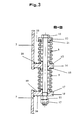
- the pairs of springs 8 and 9 are arranged, as shown in Figure 3.
- first claw 14 fastened to the structure 3
- the claw 14 being provided with a first through hole 15 for the bolt 10.
- a second claw 16 fastened to the plate 7 is provided with a second through hole 17 for the bolt 10.
- the spring 9 is arranged between a support plane 20 provided in the claw 15 and a support plane 21 which is located in one side 22 of a bush 23: the head of the bolt 10 is supported on a second side 24 opposite the first side 22.
- a screw nut 25 is supported on a plane 26 of the claw 16 for adjusting the tension of the spring 8, which determines the tension of the spring 9.
- the width of the vibrations of the plate 7 depends on the tension of the spring 9 in an inversely proportional manner.
- the spring 9 transfers the vibrations to the structure 3; nevertheless, the vibrations are damped by the elasticity of the spring 9 in order not to tension the structure 3, which is connected to the road working machine.
- the claw 14 is constructed so that it can withstand the muzzle of the material from which it is made.
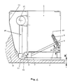
- FIG. 4 shows the paver equipped with a device for starting the stumping process of the road surface.
- This device consists of an outer-center rotor 27 and a stump 11 which is connected to the rotor 27 by a conventional connecting member 28.
- the rotor 27 drives the stump 11 alternately up and down to the beginning of the smoothing process of the road surface, which is processed by the plate 7.
- a protective member 12 is arranged in front of the hinge 6 in the direction C of the movement of the road working machine to prevent the particles of covering material from entering the hinge 6, the protective member 12 extending at least over the entire length of the hinge 6.
- the hinge 6 is an elastic hinge that combines the functions of binding with a degree of freedom between the structures 3 and 7 and of elastic connection between the same structures.
- a single spring 9 is used for the elastic connection of the structures 3 and 7, the spring 9 being equipped with a nut screw 10 for adjusting its tension.
Landscapes
- Engineering & Computer Science (AREA)
- Architecture (AREA)
- Civil Engineering (AREA)
- Structural Engineering (AREA)
- Road Paving Machines (AREA)
- Vibration Prevention Devices (AREA)
- Road Signs Or Road Markings (AREA)
Applications Claiming Priority (2)
| Application Number | Priority Date | Filing Date | Title |
|---|---|---|---|
| IT04631290A IT1243556B (it) | 1990-08-23 | 1990-08-23 | Ferro da stiro, per distesa di manti stradali, con parte inferiore oscillante attorno ad un asse posto sul ferro da stiro medesimo. |
| IT4631290 | 1990-08-23 |
Publications (2)
| Publication Number | Publication Date |
|---|---|
| EP0472094A1 true EP0472094A1 (fr) | 1992-02-26 |
| EP0472094B1 EP0472094B1 (fr) | 1995-01-11 |
Family
ID=11258601
Family Applications (1)
| Application Number | Title | Priority Date | Filing Date |
|---|---|---|---|
| EP91113566A Expired - Lifetime EP0472094B1 (fr) | 1990-08-23 | 1991-08-13 | Finisseuse pour revêtements routiers avec plaque inférieure oscillante autour d'une charnière liant cette plaque à une structure portante |
Country Status (4)
| Country | Link |
|---|---|
| EP (1) | EP0472094B1 (fr) |
| DE (1) | DE59104216D1 (fr) |
| ES (1) | ES2069140T3 (fr) |
| IT (1) | IT1243556B (fr) |
Cited By (2)
| Publication number | Priority date | Publication date | Assignee | Title |
|---|---|---|---|---|
| EP0586886A3 (en) * | 1992-09-09 | 1994-06-01 | Joseph Voegele Ag | Screed for a road paver |
| WO2013067869A1 (fr) * | 2011-11-11 | 2013-05-16 | 中联重科股份有限公司 | Plaque de repassage et dispositif d'étalement |
Citations (4)
| Publication number | Priority date | Publication date | Assignee | Title |
|---|---|---|---|---|
| FR893442A (fr) * | 1942-05-04 | 1944-06-08 | Licentia Gmbh | Appareil pour la construction de revêtements de routes en béton ou autres matériaux de remblai analogues |
| WO1980000160A1 (fr) * | 1978-06-28 | 1980-02-07 | Aebi Ag R | Machines de finition pour route en beton |
| US4313690A (en) * | 1977-12-14 | 1982-02-02 | As Phonix | Asphalt laying machine |
| DE3114049A1 (de) * | 1981-04-07 | 1982-10-14 | Joseph Vögele AG, 6800 Mannheim | Schwarzdeckenfertiger |
-
1990
- 1990-08-23 IT IT04631290A patent/IT1243556B/it active IP Right Grant
-
1991
- 1991-08-13 DE DE59104216T patent/DE59104216D1/de not_active Expired - Lifetime
- 1991-08-13 ES ES91113566T patent/ES2069140T3/es not_active Expired - Lifetime
- 1991-08-13 EP EP91113566A patent/EP0472094B1/fr not_active Expired - Lifetime
Patent Citations (4)
| Publication number | Priority date | Publication date | Assignee | Title |
|---|---|---|---|---|
| FR893442A (fr) * | 1942-05-04 | 1944-06-08 | Licentia Gmbh | Appareil pour la construction de revêtements de routes en béton ou autres matériaux de remblai analogues |
| US4313690A (en) * | 1977-12-14 | 1982-02-02 | As Phonix | Asphalt laying machine |
| WO1980000160A1 (fr) * | 1978-06-28 | 1980-02-07 | Aebi Ag R | Machines de finition pour route en beton |
| DE3114049A1 (de) * | 1981-04-07 | 1982-10-14 | Joseph Vögele AG, 6800 Mannheim | Schwarzdeckenfertiger |
Cited By (2)
| Publication number | Priority date | Publication date | Assignee | Title |
|---|---|---|---|---|
| EP0586886A3 (en) * | 1992-09-09 | 1994-06-01 | Joseph Voegele Ag | Screed for a road paver |
| WO2013067869A1 (fr) * | 2011-11-11 | 2013-05-16 | 中联重科股份有限公司 | Plaque de repassage et dispositif d'étalement |
Also Published As
| Publication number | Publication date |
|---|---|
| IT9046312A1 (it) | 1992-02-23 |
| IT1243556B (it) | 1994-06-16 |
| EP0472094B1 (fr) | 1995-01-11 |
| DE59104216D1 (de) | 1995-02-23 |
| ES2069140T3 (es) | 1995-05-01 |
| IT9046312A0 (it) | 1990-08-23 |
Similar Documents
| Publication | Publication Date | Title |
|---|---|---|
| EP0155527B1 (fr) | Dispositif pour le nettoyage des semoules | |
| DE3402861C2 (fr) | ||
| DE3128349A1 (de) | Lineare abtriebseinheit fuer einen auf einer festen abstuetzung elastisch zu lagernden schwingfoerderer | |
| DE2918935A1 (de) | Schwingfoerderer | |
| DE2136279B2 (de) | Vibratorhalterung | |
| DE2232831A1 (de) | Schwingvorrichtung zur handhabung von material und verfahren zum veraendern der richtung einer schwingkraft | |
| DE19629324C1 (de) | Vibrationsplatte mit Besohlung | |
| EP2910312A1 (fr) | Agencement oscillatoire pour une table vibrante ou un dispositif de tamisage | |
| DE2301653C3 (de) | Straßenbehandlungsgerät zur Verbesserung der Griffigkeit eines Strafien- | |
| DE2503845A1 (de) | Verfahren und vorrichtung zum schwingpolieren von einzelnen materialstuecken, insbesondere schmucksteinen in einem schwingenden behaelter | |
| DE3500173A1 (de) | Giessformvorrichtung | |
| DE3921349C2 (fr) | ||
| EP0943037B1 (fr) | Bandage pour cylindres destines au compactage du sol | |
| DE1959939A1 (de) | Vibrationseinrichtung zur Materialbehandlung | |
| DE3512215A1 (de) | Siebmaschine mit einem flexiblen siebbelag | |
| DE3741966C2 (fr) | ||
| EP1899245B1 (fr) | Transporteur vibrant lineaire | |
| EP0358632B1 (fr) | Dispositif de tamisage | |
| EP0472094A1 (fr) | Finisseuse pour revêtements routiers avec plaque inférieure oscillante autour d'une charnière liant cette plaque à une structure portante | |
| EP0374428B1 (fr) | Poutre de compactage pour une finisseuse de routes | |
| EP0586886B1 (fr) | Poutre lisseuse pour un finisseur | |
| EP0218575A2 (fr) | Dispositif de tamisage | |
| DE3035890C2 (de) | Fahrbare Gleisstopfmaschine | |
| DE3507073C2 (fr) | ||
| DE2204022B2 (de) | Abziehvorrichtung für Betonoberflächen od.dgl |
Legal Events
| Date | Code | Title | Description |
|---|---|---|---|
| PUAI | Public reference made under article 153(3) epc to a published international application that has entered the european phase |
Free format text: ORIGINAL CODE: 0009012 |
|
| AK | Designated contracting states |
Kind code of ref document: A1 Designated state(s): DE ES FR GB |
|
| 17P | Request for examination filed |
Effective date: 19920818 |
|
| RAP1 | Party data changed (applicant data changed or rights of an application transferred) |
Owner name: JOSEPH VOEGELE AG |
|
| 17Q | First examination report despatched |
Effective date: 19930910 |
|
| GRAA | (expected) grant |
Free format text: ORIGINAL CODE: 0009210 |
|
| AK | Designated contracting states |
Kind code of ref document: B1 Designated state(s): DE ES FR GB |
|
| REF | Corresponds to: |
Ref document number: 59104216 Country of ref document: DE Date of ref document: 19950223 |
|
| GBT | Gb: translation of ep patent filed (gb section 77(6)(a)/1977) |
Effective date: 19950127 |
|
| ET | Fr: translation filed | ||
| REG | Reference to a national code |
Ref country code: ES Ref legal event code: FG2A Ref document number: 2069140 Country of ref document: ES Kind code of ref document: T3 |
|
| PLBE | No opposition filed within time limit |
Free format text: ORIGINAL CODE: 0009261 |
|
| STAA | Information on the status of an ep patent application or granted ep patent |
Free format text: STATUS: NO OPPOSITION FILED WITHIN TIME LIMIT |
|
| 26N | No opposition filed | ||
| PGFP | Annual fee paid to national office [announced via postgrant information from national office to epo] |
Ref country code: FR Payment date: 20000816 Year of fee payment: 10 Ref country code: ES Payment date: 20000816 Year of fee payment: 10 |
|
| PG25 | Lapsed in a contracting state [announced via postgrant information from national office to epo] |
Ref country code: ES Free format text: LAPSE BECAUSE OF NON-PAYMENT OF DUE FEES Effective date: 20010814 |
|
| REG | Reference to a national code |
Ref country code: GB Ref legal event code: IF02 |
|
| PG25 | Lapsed in a contracting state [announced via postgrant information from national office to epo] |
Ref country code: FR Free format text: LAPSE BECAUSE OF NON-PAYMENT OF DUE FEES Effective date: 20020430 |
|
| REG | Reference to a national code |
Ref country code: FR Ref legal event code: ST |
|
| REG | Reference to a national code |
Ref country code: ES Ref legal event code: FD2A Effective date: 20020911 |
|
| PGFP | Annual fee paid to national office [announced via postgrant information from national office to epo] |
Ref country code: GB Payment date: 20050808 Year of fee payment: 15 |
|
| GBPC | Gb: european patent ceased through non-payment of renewal fee |
Effective date: 20060813 |
|
| PG25 | Lapsed in a contracting state [announced via postgrant information from national office to epo] |
Ref country code: GB Free format text: LAPSE BECAUSE OF NON-PAYMENT OF DUE FEES Effective date: 20060813 |
|
| PGFP | Annual fee paid to national office [announced via postgrant information from national office to epo] |
Ref country code: DE Payment date: 20100929 Year of fee payment: 20 |
|
| REG | Reference to a national code |
Ref country code: DE Ref legal event code: R071 Ref document number: 59104216 Country of ref document: DE |
|
| REG | Reference to a national code |
Ref country code: DE Ref legal event code: R071 Ref document number: 59104216 Country of ref document: DE |
|
| REG | Reference to a national code |
Ref country code: DE Ref legal event code: R082 Ref document number: 59104216 Country of ref document: DE Representative=s name: GRUENECKER, KINKELDEY, STOCKMAIR & SCHWANHAEUS, DE |
|
| REG | Reference to a national code |
Ref country code: DE Ref legal event code: R081 Ref document number: 59104216 Country of ref document: DE Owner name: JOSEPH VOEGELE AG, DE Free format text: FORMER OWNER: JOSEPH VOEGELE AG, 68163 MANNHEIM, DE Effective date: 20120217 Ref country code: DE Ref legal event code: R082 Ref document number: 59104216 Country of ref document: DE Representative=s name: GRUENECKER, KINKELDEY, STOCKMAIR & SCHWANHAEUS, DE Effective date: 20120217 Ref country code: DE Ref legal event code: R082 Ref document number: 59104216 Country of ref document: DE Representative=s name: GRUENECKER PATENT- UND RECHTSANWAELTE PARTG MB, DE Effective date: 20120217 |
|
| PG25 | Lapsed in a contracting state [announced via postgrant information from national office to epo] |
Ref country code: DE Free format text: LAPSE BECAUSE OF EXPIRATION OF PROTECTION Effective date: 20110814 |