EP0472255A2 - Dispositif de lecture de marques d'identification - Google Patents
Dispositif de lecture de marques d'identification Download PDFInfo
- Publication number
- EP0472255A2 EP0472255A2 EP91300105A EP91300105A EP0472255A2 EP 0472255 A2 EP0472255 A2 EP 0472255A2 EP 91300105 A EP91300105 A EP 91300105A EP 91300105 A EP91300105 A EP 91300105A EP 0472255 A2 EP0472255 A2 EP 0472255A2
- Authority
- EP
- European Patent Office
- Prior art keywords
- reading
- bar code
- print bar
- distance
- mark
- Prior art date
- Legal status (The legal status is an assumption and is not a legal conclusion. Google has not performed a legal analysis and makes no representation as to the accuracy of the status listed.)
- Granted
Links
Images


Classifications
-
- G—PHYSICS
- G06—COMPUTING OR CALCULATING; COUNTING
- G06K—GRAPHICAL DATA READING; PRESENTATION OF DATA; RECORD CARRIERS; HANDLING RECORD CARRIERS
- G06K7/00—Methods or arrangements for sensing record carriers, e.g. for reading patterns
- G06K7/01—Details
- G06K7/016—Synchronisation of sensing process
-
- G—PHYSICS
- G06—COMPUTING OR CALCULATING; COUNTING
- G06K—GRAPHICAL DATA READING; PRESENTATION OF DATA; RECORD CARRIERS; HANDLING RECORD CARRIERS
- G06K5/00—Methods or arrangements for verifying the correctness of markings on a record carrier; Column detection devices
- G06K5/02—Methods or arrangements for verifying the correctness of markings on a record carrier; Column detection devices the verifying forming a part of the marking action
Definitions
- This invention relates to an identification mark reading apparatus for reading an identification mark attached onto a moving body, and more particularly to an identification mark reading apparatus suitable for a quality test of print bar codes successively printed on a roll sheet.
- Bar codes are such that alphabets or numerals, etc. are represented by combination of black bars and white bars of different widths, and combinations of a series of bars are used as respective codes for optical input.
- Such bar codes are printed on a roll sheet by a printing machine.
- a bar code numbering machine is attached to the letterpress printing unit. According as respective letter rings of the bar code numbering machine are rotated in a direction to increment or decrement the numeric value one by one, bar codes are successively printed onto the roll sheet.
- an object of this invention is to provide an identification mark reading apparatus capable of testing the total number of identification marks such as print bar codes printed on the roll sheet by the printing machine on a real time basis.
- an embodiment of this invention is directed to an identification mark reading apparatus adapted to test whether or not identification marks such as print bar codes successively printed on a body or object in the form of sheet by a printing machine are properly printed, the apparatus comprising means for determining timings at which the identification mark should be read, reading means for sequentially reading the identification marks in accordance with the determined timings to form binarized identification mark data, means for displaying the identification mark data, judgement means for comparing the identification mark data with identification mark data of identification marks to be primarily printed to judge whether or not the identification marks are correctly printed, and means for producing a notifying signal when the judgement means judges that the identification marks are not correctly printed.
- This apparatus is directed to an identification mark reading apparatus adapted to individually read identification marks attached on a moving body or object at suitable intervals in a movement direction of the moving body or object, each comprised of a plurality of identifiers having predetermined widths in the movement direction and arranged in a direction perpendicular to the movement direction, the apparatus comprising reading means for scanning the identification mark in an arrangement direction of the identifiers at a predetermined reading position to output a reading signal, and reading timing control means for effecting a control to receive an initial reading signal of a preceding identification mark in the moving direction thereafter to inhibit the reading operation of the reading means, or to inhibit the processing of a reading signal by a time corresponding to a distance shorter than a distance required until at least a succeeding identification mark succeeding to the preceding identification mark reaches the reading position to restart the reading operation or processing after movement of the inhibited distance.
- the identification mark reading apparatus is constituted as above, thus making it possible to securely read the total number of identification marks per each reading operation.
- This apparatus is directed to an identification mark reading apparatus for individually reading a plurality of identification marks arranged at mark positions having a fixed interval in a movement direction of a moving body or object, each identification mark being comprised of a plurality of identifiers arranged in a direction perpendicular to the movement direction, the apparatus comprising a plurality of reading means for respectively scanning the plurality of identification marks in the arrangement direction of the identifiers at the predetermined reading positions to output reading signals, and reading timing control means for controlling to cause reading means of the plurality of reading means corresponding to an arbitrary mark position to scan, after the object moves a distance, from the time point when any one of a plurality of first reference positions set at a fixed interval in the movement direction of the moving object passes through a reference plane including a second reference position set at a fixed point outside the moving body and being perpendicular to the movement direction, the distance corresponds to
- the identification mark reading apparatus of this embodiment is constituted as above, even in the case where a plurality of identification marks are printed by repetition of a fixed layout, it is possible to securely read the total number of identification marks one by one.
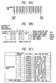
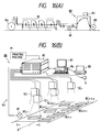
- a bar code is such that alphabetical characters or numeric characters are represented by combination of black bars and white bars of different widths as shown in FIG. 1(A). Combination of a series of bars is used as a code for an optical input, etc..
- This bar code includes a start code and an end code indicated by alphabetic character positioned on the both sides, respectively, and bars indicating numeric characters arranged inside. Further, numeric characters or numerals that respective bars indicate are appended for visual confirmation at the lower part of the bars.
- Each numeral is constituted, as shown in FIG. 1(B), by four black bars of two kinds of widths and three white bars constituting gaps between four black bars, i.e., information of 7 bits.
- FIG. 1(C) Numerals are represented using individial patterns by thicknesses of bars and combination of bars arranged in parallel. This pattern is shown in FIG. 1(C). Although there are bar codes representing numeral by different bar patterns in addition to the bar pattern shown in FIG. 1(B), the bar pattern shown in FIG. 1(C) is widely used at present.
- FIG. 2 A continuous document on which such a bar code is printed is shown in FIG. 2.
- This continuous document is constituted in a manner that rectangular documents 51 to 55 overlap with each other in upper and lower directions and the left end portion 61 is bound.
- Respective documents 51 to 55 are such that patterns, tables or the like are printed on roll papers different from each other. Bar codes are printed on the documents every respective roll sheets at a printing machine.
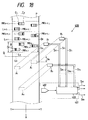
- FIG. 3 shows an offset form rotary press for carrying out a printing onto the roll sheets for making up a continuous document to which this invention is applied in one form.
- This offset form rotary press machine is ordinarily composed of a paper supply unit, an offset unit, a letterpress-number printing unit, a processing unit, a bending unit, and a winding unit.
- a carbon printing unit may be additionally provided.
- a press cylinder of the letterpress-number printing unit after an offset printing is completed is replaced with a number shaft to attach a bar code numbering machine to thereby print bar codes.
- a plurality of bar code numbering machines are ordinarily attached onto a single number shaft. Thus, a multi-plane printing is carried out.
- the roll sheet is winding-ejected, or is subjected to sheet cutting or bent at the bending unit, and is ejected.
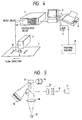
- the printing bar code automatic testing apparatus of the first embodiment of this invention is constituted as shown in FIG. 4.
- a printing bar code reading unit 2 serves to read printing bar codes 1a continuously printed on a roll sheet 1 flowing in a direction indicated by an arrow.
- a He-Ne gas laser output unit 11 outputs a laser beam A. After the laser beam A passes through a lens section 12, it is reflected by a half-mirror 15 and a rotary polygon mirror 13 rotated by a motor 14 to scan the print bar codes 1a. Although the rate of reading the print bar codes 1a depends upon what number of times the laser beam A scans the print bar code 1a per unit time, the number of times is determined by the rotational speed of a motor 14 and the number of planes of the rotary polygon mirror 13.
- the motor 14 rotates, e.g., a rotary polygon mirror having ten planes at 50 (rps), 500 times of scanning area carried out per each second.
- 500 times of scanning area carried out per each second.
- the laser beam A which has scanned the print bar codes 1a and has been reflected is reflected by the rotary polygon mirror 13 for a second time, and is focused on a light receiving element 17 after passed through a condenser lens 16.
- the light receiving element 17 outputs an analog current signal indicative of a pattern of the print bar codes 1a.
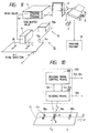
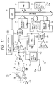
- FIG. 6 The block diagram showing the light receiving element 17 and sections succeeding thereto is shown in FIG. 6.
- An analog current signal outputted from the light receiving element 17 is subjected to current-to-voltage conversion by an operational amplifier 21.
- the signal thus obtained is delivered to a comparator 22 as an analog voltage signal.
- the comparator 22 determines a slice level by a set value that a slice level setting circuit 23 has set and changes an analog voltage signal inputted from the operational amplifier 21 to a binarized digital signal of "1" or "0" to output that digital signal.
- the value of "1” signifies the white belt portion on the print bar code
- the value of "0” signifies the black belt portion on the print bar code.
- the length of the time period during which the digital signal of "1” or “0” is outputted is varied in dependency upon the lengths of respective belts.
- the circuit for measuring the lengths of times of respective digital signals are a white belt counter 24 and a black belt counter 25.
- An output from the comparator 22 and an oscillation pulse output from an oscillator 26 are inputted to the white belt counter 24 through an AND circuit 27.
- the white belt counter 24 counts the number of pulses at the portion corresponding to the white belt.
- An output of an inverter 34 obtained by inverting an output from the comparator 22 and an oscillation pulse output from the oscillator 26 are inputted to the black belt counter 25 through an AND circuit 28.
- the black belt counter 25 counts the number of pulses at the portion corresponding to the black belt.
- Count values from respective counters 24, 25 are taken into a CPU 30 through a data bus 29.
- the CPU 30 inputs a count value of the white belt counter 24 signifying the length of the white belt immediately before the black belt (step 103).
- the CPU 30 outputs a clear signal to the white belt counter 24 through the parallel input/output circuit 33.
- the CPU 30 compares respective count values of the white and black belts with the code table of FIG. 1(C) stored in the ROM 31 to convert compared results to corresponding numeric values (step 104).
- the CPU 30 recognizes the end code (step 105)
- the CPU 30 outputs converted results to the data bus 29.
- the serial input/output circuit 32 outputs the converted result as serial data to the calculation processing judgement unit 4 in FIG. 8 (step 106).
- the photoelectric switch 3 determines the timing at which the print bar code reading unit 2 should read the print bar code 1a to inform it.
- the print bar code reading unit 2 is informed of it from the photoelectric switch 3 as a timing signal.
- the reading unit 2 read it for a time period during which the timing signal is generated. Since the timing for reading the print bar code 1a is determined in this way, even if the interval in which the print bar code 1a is printed is varied depending upon the printing items, the print bar code can be securely read.
- a reading disable signal is outputted to the calculation processing judgement unit 4 after the time period during which the timing signal is generated is completed.
- the host computer 5 has a function to transfer test start and test end instructions to the calculation processing judgement unit 4.
- the serial-to-parallel conversion unit 4g of the calculation processing judgement unit 4 converts print bar code data received from the print bar code reading unit 2 from serial data to parallel data to transmit the parallel data to the programmable input/output interface circuit 4c.
- the CPU 4a receives the converted print bar code data from the programmable input/output interface circuit 4c to store, into the memory 4b, data corresponding to the number of digits every one byte.
- the print bar code data which has been read at the first reading operation and stored into the memory 4b serves as a reference value for calculating bar code data to be primarily printed at the second reading operation and those subsequent thereto.
- the CPU 4a judges that any extraordinary state has taken place in the print bar code 1a
- the CPU 4a transmits that bar code data and the kind of extraordinary state to the host computer 5 through the data transfer interface circuit 4f.
- the host computer 5 outputs that print bar code data to the printer 6 or the CRT 9, or allows the alarm 7 to produce an alarm.
- the host computer 5 also outputs an extraordinary state occurrence time to the printer 5 or the CRT 9.
- an operating signal is transmitted from the printing machine 8 to the host computer 5 in order to discriminate whether the print bar code 1a in which that extraordinary state has occurred is printed on the print spare portion or on a normal sheet.
- the information indiating the portion where the extraordinary state has occurred will be outputted to the printer 6 or the CRT 9.
- both data of the printing bar code data which has been read and the bar code data to be primarily printed which has been obtained by calculation are displayed over the total number of these bar code data on a 7 segment LED indicator 4e by a 7 segment LED drive circuit. Accordingly, an operator can visually make comparative judgement of both data.
- the print bar code automatic testing apparatus of this embodiment serves to test whether or not the print bar codes over the total number thereof on a real time basis in the middle in printing. For this reason, where any extraordinary state occurs in the print bar codes, prompt measure such as a measure to immediately to stop running of the printing machine can be taken, thus preventing the printing time or the roll sheet from becoming wasteful. Further, since an output to the alarm or the printer varies in dependency upon the kind of an extraordinary state such as whether or not an emergent measure is required to be taken, a suitable measure can be adopted. In addition, since this apparatus is relatively inexpensive and no visual test by an operator is required, the operator's labor can be effectively lessened.
- the configuration of the first embodiment is only an example, but does not limit the identification mark reading apparatus of this invention.
- a print bar code which has been read at the first reading operation is used as a reference value for calculating bar code data of a print bar code to be primarily printed in the above-mentioned embodiment, data set in advance at the host computer 5 by an operator may be used.
- the photoelectric switch 3 is used as means for determining a timing at which the print bar code 1a should be read, an approach may be employed to determine a timing from the rotary shaft of the printing machine 8 by using a rotary encoder, etc., or to allow the print bar code reading unit 2 itself to find out a print bar code 1a from on the roll sheet 1 to read it.
- a laser output unit based on a laser system except for He-Ne gas laser may be used. Further, in the case of conducting a reading operation without using a laser beam, a laser output unit based on a system of conducting a reading by a camera or a line sensor system, etc. may be adopted. As the method of informing an operator of an extraordinary state produced in the print bar code, an alarm or an output to the printer, or an output to the CRT, etc. may be utilized.
- the print bar code automatic testing apparatus of the first embodiment serves to determine a timing at which the print bar code should be read to sequentially print bar codes in accordance with the determined timing to use data thus read as print bar code data in a numerical form. This apparatus then displays the print bar code, and compares it with a numeric value of a bar code to be primarily printed to judge whether or not the print bar code is correctly printed to produce a signal when it is judged that the print bar code is not correctly printed.
- the means for reading print bar codes allows a laser beam outputted from the laser beam output unit to scan the print bar codes by rotating the rotary polygon mirror to condense a reflected laser beam to thereby read the total number of print bar codes.
- the photoelectric switch does not respond thereto, and/or in the case where there is any print portion of high density in the vicinity of the portion where no print bar code exists, the photoelectric switch erroneously responds thereto. Accordingly, it is required to make adjustments every roll sheets so that the response speed of the photoelectric switch becomes optimum.
- the testing apparatus of the first embodiment at least two times of scanning are made with respect to one print bar code.
- only initial data obtained by the first scanning is required, but data obtained by the second scanning and those subsequent thereto are unnecessary.
- the quality judgement rather becomes complicated. Accordingly, after only data at the time of first scanning is read, it is necessary to adopt a mechanism such that the photoelectric switch is turned OFF. For this purpose, it is necessary to adjust the reading timing on the basis of the photoelectric switch position, the optical reading unit position, and the printed matter carrying speed. Such an adjustment will be left to an operator of the printing line. As a result, skill was considerably required for an operator.
- a second embodiment is directed to an apparatus constructed so as to securely permit detection of identification marks such as print bar codes attached onto a moving object.
- This print bar code testing apparatus includes a print bar code reading apparatus 73 which is an identification mark reading apparatus according to this invention, a calculation processing judgement unit 4, a host computer 5, a printer 6, an alarm 7, and a CRT 9.
- the print bar code reading apparatus 73 has a print bar code reading unit 71 serving as reading means, and a reading timing control unit 72 serving as reading timing control means.
- the reading timing control unit 72 includes a timing pulse generation unit 72a and a pulse control unit 72b.
- the print bar code reading unit 71 reads a print bar code BC which is an identification mark printed at a suitable interval on a roll sheet P R which is an object flowing in a direction X indicated by an arrow in FIG. 9.
- the print bar code BC is as shown such that a plurality of black bars or white bars each serving as an identifier are arranged in a direction Y perpendicular to a movement direction X of the roll sheet P R .
- the pulse control unit 72b outputs, to the print bar code reading unit 1, a timing at which the print bar code reading unit 71 should read the print bar code BC.
- FIG. 10 is an explanatory view showing the principle of the second embodiment.
- this idenfication mark reading apparatus 203 serves as an identification mark reading apparatus for individually reading identification marks MK1 to MK n attached at a suitable interval in a movement direction X of an object on a moving object P, and each having a predetermined width B in the movement direction and comprised of a plurality of identifiers C1 to C n arranged in a direction Y perpendicular to the movement direction X.
- This apparatus comprises reading means 201 for scanning identification marks MK1 to MK n in the arrangement direction Y of the identifiers C1 to C m at a predetermined reading position A to output a reading signal S RD , and reading timing control means 202 for effecting a control to receive an initial reading signal S RD of a preceding identification mark MK i-1 in the movement direction X thereafter to inhibit the reading operation of the reading means 201, or to inhibit the processing of a reading signal by a time corresponding to a distance shorter than a distance required until at least a succeeding identification mark MK i succeeding to the preceding identification mark MK i-1 reaches the reading position A to restart the reading operation or processing after movement of the inhibited distance.
- a semiconductor laser output unit 112 outputs a laser beam L. After passed through a lens section 113, the laser beam L is reflected by a rotary polygon mirror 115 rotating by a motor 114 to scan the print bar codes serving as the identification marks in a direction Y-Y.
- the speed for reading the print bar code BC depends upon how many times the laser beam L scans the print bar code BC per unit time. This number of times is determined by the rotational speed of the motor 114 and the number of planes of the rotary polygon mirror 113.
- the analog current signal outputted from the light receiving element 17 is subjected to current-to-voltage conversion by the operational amplifier 18, and is delivered to the comparator 22 as an analog voltage signal S1 serving as a reading signal.
- the operational amplifier 22 and components succeeding thereto shown in a block form are the same as those in the first embodiment shown in FIG. 6 except that the second embodiment includes the reading timing control unit 72.
- the operation of the second embodiment differs from that of the first embodiment in that when an analog voltage signal S1 serving as an initial reading signal is delivered from the operational amplifier 18 to the pulse control unit 72b of the reading timing control unit 72, the pulse control unit 72b outputs a reading stop signal S2 to count the number of pulses from a timing pulse generation unit 72a to output a reading restart signal S2 after a predetermined inhibit time has passed.
- this reading timing control unit 72 comprises a timing pulse generation unit 72a and a pulse control unit 72b.
- the timing pulse generation unit 72a includes two gears 41 and 42, and a rotary encoder 43.
- the pulse control unit 72b includes a RS-422 receiver 44, a pulse counter 45, a pulse number conversion circuit 46, and a photo coupler 47.
- the rotary encoder 43 is connected to the pulse counter 45 and the pulse number conversion circuit 46 through the RS-422 receiver 44. Further, the pulse counter 45 is connected to the print bar code reading unit 71 through the photo coupler 47.
- the gear 41 is attached to the shaft of the press cylinder PC to transmit the rotation of the press cylinder PC to the rotary encoder 43 through the gear 42.
- the rotary encoder serves as an encoder to measure a rotary angle displacement and generates 100 to 50,000 timing pulses per each rotation.
- the number of pulses mentioned above is called a resolution.
- a rotary encoder having a resolution of 1000 pulses per each rotation is employed.
- each pulse signal is transmitted to the RS-422 receiver 44 as a signal S4.
- the signal S4 is converted to signals S6 and S7 at the RS-422 receiver 44. They are transmitted to the pulse counter 45 and the pulse number conversion circuit 46, respectively.
- the print bar code reading unit 71 outputs a GO signal S1 serving as an initial reading signal to the pulse counter 45.
- the pulse counter 45 receives a GO signal S3 through the photo coupler 47, the pulse counter 45 returns the count value to zero (count clear) to start a count operation of the timing pulse from that time point. Further, at the same time, the pulse counter 45 outputs a SYNC signals S2 of "L" level (low level) serving as a reading stop signal through the photo coupler 47 (FIG. 13).
- a reading stop section length serving as an inhibit distance is inputted in advance as a set data signal S8 from the external to the pulse number conversion circuit 46.
- the reading stop section length is defined as a length to ensure that after a print bar code BC is read once, the same print bar code is not read for a second time. It is sufficient that this length is longer than the length l a in FIG. 2. From a practical point of view, the above-mentioned length is set to a length including a fixed margin in addition to the length l a .
- the pulse counter 45 When the number of pulses reaches a set pulse number N, i.e., time reaches a reading restart time, the pulse counter 45 outputs a SYNC signal S2 of "H" level (high level) serving as a reading restart signal (FIG. 13). Namely, a period T STOP during which the SYNC signal S2 is at "L" level is an inhibit time corresponding to an inhibit distance where reading of print bar codes is not carried out.
- the SYNC signal is ordinarily at "H” level and is in a reading state at all times (step 301).
- the SYNC signal is caused to shift to "L” level, so the reading operation is stopped (step 303).
- the SYNC signal is caused to shift to "H" level for a second time (step 301).
- the pulse control unit 72b outputs a reading stop signal and a reading restart signal S2.
- an approach may be employed to output a reading stop signal as a signal S 2A to the CPU 30 thereafter to inhibit/restart data processing, or an approach may be employed to output a reading stop signal as a signal S 2B to AND circuits 27 and 28 to inhibit/restart the operation of the white belt counter 24 and the black belt counter 25 and sections succeeding thereto.
- an approach may be employed to interrupt/open the optical path of a laser beam L scanning the print bar codes BC to inhibit/restart the optical reading operation.
- the timing pulse generation unit 72a serves as a speed detection unit and a pulse generation unit.
- the pulse counter 45 constitutes a pulse count unit
- the pulse number conversion circuit 46 constitutes a pulse number conversion unit.
- the identification mark to be detected is not limited to the bar code, but may be codes/marks of other kinds, etc..
- a laser system except for the semiconductor laser e.g., He-Ne gas laser, etc. may be used as the laser output unit.
- the semiconductor laser e.g., He-Ne gas laser, etc.
- the pulse generation unit may be not only a rotary encoder but also an ordinary clock generation circuit, and may include various speed sensors as the speed detection unit to adjust the number of the pulses in dependency upon a body movement speed.
- the reading stop signal and the reading restart signal signals of other kinds may be employed.
- the reading stop signal shifts to "H" level at the rising of a positive pulse signal and the reading restart signal shifts to "L” level at the time of restarting reading operation.
- this apparatus is suitable as the detection unit of an apparatus for checking, whether or not the total number of identification marks printed on a print roll sheet is good.
- an apparatus for checking development state of all the processes of flow production such as automation, or the like.
- this apparatus can be applied to all systems utilizing a mechanism capable of securely checking identification marks on a moving body.
- the print bar code reading apparatus of the second embodiment can only cope with the case of one print bar code with respect to one document. Accordingly, if an attempt is made to use a plurality of reading apparatuses in this form to test a document including a plurality of print bar codes as shown in FIG. 15, rigorous adjustment/setting of the set position and the scanning timing of the scanner cannot be made.
- a third embodiment is constructed to securely permit detection of the plurality of identification marks such as a plurality of print bar codes, etc. attached by a fixed layout on a moving body by simple adjustment work.
- the print bar code testing apparatus 88 is arranged as shown in FIG. 16(A) at the preceding stage position of a take-up roll 89 in the printing line.
- a roll sheet P R is wound out, and the print bar codes BC are printed for a time period during which the roll sheet P R is passed through the printing machine M.
- the position and the speed of the preceding print bar code on the roll sheet P R are detected by a rotary encoder 81 arranged in the line.
- the print bar code testing apparatus 88 comprises, as shown in FIG. 16(B), a print bar code reading unit 83 which is an identification mark reading apparatus according to this invention, a host computer 84, a printer 85, an alarm 86, and a CRT 87.
- the print bar code reading unit 83 includes a rotary encoder 81, a plurality of scanners SC1 to SC n , and a computational processing judgement unit 82.
- a plurality of scanners SC1 to SC n read a plurality of identification marks printed by a fixed layout at a fixed interval on a roll sheet P R which is a body flowing in a direction X
- the scanner SC i corresponds to print bar codes BC1, i , ... , BC x , i , ..., BC Y , i .
- print bar codes BC are such that a plurality of black bars or white bars serving as identifiers of the print bar codes BC are arranged in a direction Y perpendicular to the movement direction X of the roll sheet P R .
- the computational processing judgement unit 82 outputs a timing at which the scanners SC1 to SC n should read the print bar codes BC.
- Respective functions are operations of the computational processing judgement unit 82, the host computer 84, the printer 85, the alarm 86, and the CRT 87 will now be described with reference to FIG. 17.
- initial date such as the number of digit set in advance by an operator, the kind of check digits, or the like is transmitted from the host computer 84 to an interface board (not shown) of the computational processing judgement unit 82.
- This initial data is transmitted to a CPU (not shown) through an interface for carrying out control and matching of input/output of respective data, and is then stored into a memory (not shown).
- the host computer 84 has a function to transfer test start and test end instructions to the computational processing judgement unit 82.
- the computational processing judgement unit 82 converts print bar code data read by respective scanners SC1 to SC n to parallel data to transmit the parallel data to the interface.
- the CPU receives the converted print bar code data from the interface to store, into the memory, data corresponding to the number of digits every one byte.
- the print bar code data which has been read at the first reading operation and stored into the memory serves as a reference value for calculating bar code data to be primarily printed at the second reading operation and those subsequent thereto.
- the CPU judges that any extraordinary state has taken place in the print bar code BC
- the CPU transmits that bar code data and the kind of extraordinary state to the host computer 84 through the interface.
- the host computer 84 outputs that print bar code data to the printer 85 or the CRT 87, or allows the alarm 86 to produce an alarm.
- the host computer also outputs an extraordinary state occurrence time to the printer 85 or the CRT 87.
- an operating signal is transmitted from the printing machine M to the host computer 85 in order to discriminate whether the print bar code in which that extraordinary state has occurred is printed on the print spare portion or on a normal sheet.
- the information indicating the portion where the extraordinary state has occurred will be outputted to the printer 85 or the CRT 87.
- both data of the print bar code data which has been read and the bar code data to be primarily printed which has been obtained by calculation are displayed over the total number of these bar code data on an LED indicator (not shown). Accordingly, an operator can visually make comparative judgement of both data.
- FIG. 18 is an explanatory view showing the principle of the third embodiment.
- this identification mark reading apparatus 400 is constructed to individially read a plurality of identification marks MK arranged at mark positions having a fixed interval D P in a movement direction X of a moving body P, each comprises of a plurality of identifiers C1, ..., C m having a predetermined length B in the movement direction X and arranged in a direction Y perpendicular to the movement direction.
- This identification mark reading apparatus 400 includes a plurality of reading means R1 to R n , and reading timing control means 401.
- the plurality of reading means R1 to R n respectively scan the plurality of identification marks MK in the arrangement direction Y of their identifiers at predetermined reading positions A1 to A n to output reading signals.
- the reading timing control means 401 effects a control as follows. Namely, reading timing control means 401 controls to cause reading means R i of the plurality of reading means R1 to R n corresponding to an arbitrary mark position MK x , i to scan, after the object P moves a distance, from the point when any one of a plurality of first reference positions L1, ..., L X , ..., L Y set at a fixed interval D p in the movement direction X of the moving object P passes through a reference plane L R including a second reference position Q set at a fixed point outside the moving body P and being perpendicular to the movement direction X, the distance corresponds to a value expressed by the following equation: r ⁇ D xi + D p - r(D Ri ) ⁇ where the fixed interval is disignated by D p , a distancefrom any one of first reference positions up to the arbitrary mark position is designated by D xi , a distance from a reading position of the reading means scanning the
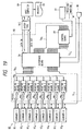
- the configuration of the print bar code reading apparatus 83 of the third embodiment is shown in a block form in FIG. 19.
- the print bar code reading apparatus 83 includes scanners SC1 to SC8, a rotary encoder 81, and a computational processing judgement unit 82.
- the computational processing judgment unit 82 includes reading boards RB1 to RB8, a control board CB, and an interface board IB.
- the scanners SC1 to SC8 and the reading boards RB1 to RB8 constitute reading means
- the control board CB constitutes reading timing control means and the reading timing control unit.
- the rotary encoder 81 constitutes a position detection unit.
- the configuration of the scanners and the decoders in those scanners is shown in FIG. 20.
- a basic configuration of the scanners and the decorders in those scanners is the same as that of the second embodiment shown in FIG. 11. Further, the scanner SC i may be connected with the control board CB as shown in FIG. 20, in addition to an example of connection shown in FIG. 19.
- Print bar codes BC x , 1, BC x , 2, and BC x , 3 are attached to the document P Rx .
- the document P Rx has a length of d p in the movement direction. This length d p also indicates an interval between, e.g., a print bar code BC x , 1 and a print bar code BC x+1 , 1 on the next document P R , x+1 .
- the print bar code BC x , 1 indicates an initial print bar code of the document P Rx with respect to the movement direction X.
- the print bar code BC x , 2 is located at a position succeeding to the print bar code BC x , 1 with respect to the movement direction.
- Respective print bar codes BC x , 1 to BC x , 3 have a length of d B with respect to the movement direction X.
- a line obtained by extending the forefront boundary line with respect to the movement direction of the initial print bar code BC x , 1 is designated by l x1
- the print bar code BC x , 1 is referred to as a reference bar code
- l x1 is referred to as a first reference line.
- the layouts of respective print bar codes BC x , 1 to BC x , 3 are fixed with respect to all the documents.
- the first reference line l x1 serves as a first reference position.
- the first reference lines, i.e., first reference positions are set with respect to respective documents. They move along with the body P.
- scanners for reading print bar codes are arranged as shown in FIG. 21(A). Namely, scanners SC1 to SC3 are arranged immediately above the loci of respective print bar codes in order that they can scan the respective print bar codes.
- a line l2 obtained by extending a projector of the forefront boundary line of the scanner SC1 corresponding to the reference bar code BC x , 1 is referred to as a second reference line, and the scanner SC1 is referred to as a reference scanner.
- the second reference line l2 serves as a second reference position or a reference plane. While the positions of respective scanners may be arbitrarily set, they are fixed posititons in space with respect to a document. Accordingly, the second reference line, i.e., the second reference position is the fixed position in space.
- a timing pulse is outputted from the rotary encoder 81 to the control board CB.
- the rotary encoder serves as an encoder to measure a rotational angular displacement. Such encoders to generate 100 to 50,000 timing pulses per each rotation. This number of pulses is called a resolution. In this embodiment, a rotary encoder having a resolution of 1000 pulses per each rotation is employed.
- the rotational ratio between a press cylinder (not shown) in the printing machine M and the rotary encoder 81 is assumed to be A : B, 1000 ⁇ B/A timing pulses are outputted every time the press cylinder makes one rotation.
- the number of pulse counts N p corresponding to the document length d p is expressed below:
- the number of pulse counts N p is expressed as follows:
- the numbers of counts N2 and N3 corresponding to the respective distances d2 and d3 are expressed as follows:
- the numbers of counts such that the front end of the reference bar code BC x , 1 is set to 0 are referred to as the A-phase count.
- a count (zero) generated every time the encoder makes one rotation is referred to as a Z-phase count.
- the number of scan counts N S2 which is the number of counts at which the print bar code BC x , 2 should be scanned is expressed as follows:
- r(X) represents a remainder (integer value) in the case where x is divided by N p .
- N p 100 counts
- N p ⁇ d i /d p represents a distance d i from the first reference line l x1 up to the print bar code BC x , i .
- N p represents a fixed length (fixed period) d p .
- N p ⁇ d si /d p represents a distance from the reference plane l2 up to the scanner SC i .
- the meaning of the equation of the right side is as follows. If the scanner SC i is present on the first reference line, it is sufficient to conduct a scanning after the count value of N p ⁇ d i /d p from the reference count.
- N p the scanner SC i is spaced from the reference plane l2 by d si , it is required to make a substraction corresponding to N p ⁇ d si /d p .
- r(N p ⁇ d si /d p ) or N p ⁇ d si /d p itself may be used.
- the reason why N p is added is to allow x of r(x) to be positive value.
- N Si may be expressed as follows:
- N Si since division by N p is carried out in determining N Si , it is possible to specify what number of documents a print bar code scanned belongs to by the value of quotient. Measured data is transmitted to the host computer 84 through the interface to specify which print bar code the measured data belongs to by document layout data and scanner position data determined in advance. Since a position difference of the specified data with respect to the reference bar code is made clear, an approach is employed to apply seeming addition or subtraction to the print bar code of a document including the reference bar code to make data uniform to thereby judge correspondence of data in the document includidng the refernece bar code.
- the period for scanning the scanner (pulse number N B ) may be about 1.5 N B which is a value obtained by further adding a marginal value to the above-mentioned N B .
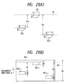
- the above-mentioned reading timing control may be conducted by using another method shown in FIG. 22.
- Print bar codes BC x , 1 , BC x , 2 and BC x , 3 are attached to the document P RX .
- the document P RX has a length of d p in the movement direction.
- the length d p also represents an interval between, e.g., a print bar code BC x , 1 and a print bar code BC x+1 , 1 on the next document P R , x+1 .
- the print bar code BC x , 1 is an initial print bar code of the document P RX with respect to the movement direction.
- the print bar code BC x , 2 is located at a position succeeding to the print bar code BC x , 1 with respect to the movement direction.
- the print bar code BC x , 3 is located at a position succeeding to the print bar code BC x , 2 with respect to the movement direction.
- Respective print bar codes BC x , 1 to BC x , 3 have a length of d B with respect to the movement direction.
- a line obtained by extending the forefront boundary line with respect to the movement direction of the initial print bar code BC x , 1 is designated by l x1
- the print bar code BC x , 1 is referred to as a reference bar code
- l x1 is referred to as a first reference line.
- the layouts of respective print bar codes BC x , 1 to BC x , 3 are fixed with respect to all the documents.
- the first reference line l x1 serves as a first reference position.
- the first reference lines, i.e., first reference positions are set with respect to respective documents. They move along with the body P.
- scanners for reading print bar codes are arranged as shown in FIG. 22(B). Namely, scanners SC1 to SC3 are arranged immediately above the loci of respective print bar codes in order that the scanners scan the respective print bar codes.
- a line l2 obtained by extending a projector of the forefront boundary line of the scanner SC corresponding to the reference bar code BC x , 1 is referred to as a second reference line
- the scanner SC1 is referred to as a reference scanner.
- the second reference line l2 serves as a second reference position or a reference plane. While the positions of respective scanners may be arbitrarily set, they are fixed positions in space with respect to a document. Accordingly, the second reference line, i.e., the second reference position is the fixed position.
- the number of counts at this moment is assumed as a reference scanner count N S1 .
- the reference scanner SC1 By allowing the reference scanner SC1 to scan for a time period corresponding to a count from the reference scan count N S1 to the count N B , it is possible to read the reference bar code BC x , 1.
- the reference scan count N S1 is assumed to be equal to zero
- the number of scan counts N S2 which is the number of counts at which the print bar code BC x , 2 should be scanned is expressed as follows:
- r(x) represents a remainder (integer value) in the case where x is divided by N p .
- N p 100 counts
- a scan count N Si required for scanning the print bar code BC x , i having the position of the distance d i from the first reference line by a certain scanner SC i becomes equal to the number of counts expressed below when the reference scan count N S1 is taken as a reference.
- N p ⁇ d i /d p represents a distance d i from the first reference line l x1 up to the print bar code BC x , i .
- N p ⁇ d si /d p represents a distance from the reference plane l2 up to the scanner SC i .
- the meaning of the equation of the right side of N Si represents a count corresponding to a distance from the print bar code BC x' 1 up to the scanner SC i .
- N Si is expressed as follows:
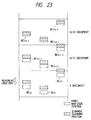
- FIG. 23 A method of providing a scanning timing of the reference scanner is shown in FIG. 23.
- the hatching portions represent positions scanned by the scanner.
- the scanning position by the scanner is backward with respect to an actual print bar code position, and it is indicated that synchronization is delayed.
- the (X + 1) document synchronization is shifted to a leading position of a very small quantity, but bar code has not been yet read.
- the (X + 2) document it is indicated that all bar codes can be read by further shifting the synchronous position to a leading position.
- step 504 in the case where all the scanners cannot be read, rough adjustment is carried out until they can be read (step 505). Further, fine adjustment after synchronization is once provided is carried out at steps 506 to 512 (steps 520 to 523, 530 to 536, 540 to 546).
- the control board comprises a 15 bit additive counter (not shown) in order to count A-phase.
- this 15 bit additive counter is used to take a measure such that an absolute position in synchronization is not shifted by delays in processing.
- this counter is cleared.
- the rotation number ratio between the press cylinder and the encoder is 1 : 1
- there is no problem there is no problem.
- the Z-phase count becomes in correspondence with the first reference line on the document for a second time.
- how many number of times K makes return the Z-phase to the original position is determined to carry out count clear only once every number of times K.
- K is a value of B obtained by reducing the ratio of A : B.
- 8 bit subtractive counters (not shown) are used as the interrupt processing "interrupt 1" to "interrupt 8 ". The reason why these counters is that the polling processing becomes complicated in the case of the pentadecimal counter, resulting in the possibility that the total number test may not be conducted. In this case, since any errors may be accumulated in the case of the interrupt processing by the subtractive counter, correction by the Z-phase clear is carried out.
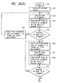
- FIGS. 25 and 26 show a flowchart (steps 600 to 619) of the outline of the reading board.
- FIG. 25 is a flowchart for reading operation (communication) from respective scanners
- FIG. 26 is a flowchart for checking read data.
- FIG. 27 is a flowchart (steps 700 to 712) of the outline of the host computer.
- step 601 indicates "start of text ?”
- step 602 indicates “cancel?"
- step 604 indicates "carriage return ?”.
- control board CB controls the read timing.
- an approach may be employed to receive an initial reading signal from the CPU 30 thereafter to output a signal S Ti1 to the CPU 30 to inhibit/restart data processing subsequent thereto, or an approach may be employed to output a signal S Ti2 to AND circuits 27 and 28 to inhibit/restart the white and black belt counters 24 and 25 and components succeeding thereto. Further, an approach may be employed to interrupt/open the optical path of a laser beam L scanning the print bar code BC to inhibit/restart the optical reading operation.
- identification marks to be detected are not limited bar codes, but may be codes/marks of other kinds, etc.. It is not necessarily required that bar codes within one document are all the same. If such bar codes are all different from each other, they can be read.
- a laser system except for the semiconductor laser e.g., a He-Ne gas laser, etc. may be used as the laser output unit.
- a reading system by a camera, a line sensor system, or a system using infrared ray or magnetism, etc.
- the position detection unit may be not only a rotary encoder but also an ordinary clock generation circuit, and may include various speed sensors as the speed detection unit to adjust the number of pulses in dependency upon a body movement speed.
- first reference line serving as the first reference position and the second reference line serving as the second reference position may be selected at other positions.
- an approach may be employed to select the first reference line at a position spaced by 1/2 d B from the forefront end of the reference bar code, i.e., at the central portion of the reference bar code with respect to the movement direction, and to select the second refence line at the central portion of the reference scanner SC1.
- N B may take other values.
- this apparatus since it is possible to scan the total number of a plurality of identification marks such as print bar codes arranged at a fixed layout, etc. to securely read them one by one, this apparatus is suitable as the detection unit of an apparatus for checking whether or not the total number of identification marks printed on a print roll sheet is good.
- an apparatus for checking development state of all the processes of flow production such as automation, or the like.
- this apparatus can be also applied to all systems utilizing a mechanism capable of securely checking identification marks on a moving body.
Landscapes
- Engineering & Computer Science (AREA)
- Physics & Mathematics (AREA)
- General Physics & Mathematics (AREA)
- Theoretical Computer Science (AREA)
- Artificial Intelligence (AREA)
- Computer Vision & Pattern Recognition (AREA)
- Printers Characterized By Their Purpose (AREA)
- Controlling Sheets Or Webs (AREA)
- Accessory Devices And Overall Control Thereof (AREA)
- Discharge Of Articles From Conveyors (AREA)
Applications Claiming Priority (4)
| Application Number | Priority Date | Filing Date | Title |
|---|---|---|---|
| JP2219615A JP2744340B2 (ja) | 1990-08-21 | 1990-08-21 | 識別マーク読取装置 |
| JP219615/90 | 1990-08-21 | ||
| JP302903/90 | 1990-11-07 | ||
| JP2302903A JP2758982B2 (ja) | 1990-11-07 | 1990-11-07 | 識別マーク読取装置 |
Publications (3)
| Publication Number | Publication Date |
|---|---|
| EP0472255A2 true EP0472255A2 (fr) | 1992-02-26 |
| EP0472255A3 EP0472255A3 (en) | 1992-10-21 |
| EP0472255B1 EP0472255B1 (fr) | 1996-11-27 |
Family
ID=26523243
Family Applications (1)
| Application Number | Title | Priority Date | Filing Date |
|---|---|---|---|
| EP91300105A Expired - Lifetime EP0472255B1 (fr) | 1990-08-21 | 1991-01-08 | Dispositif de lecture de marques d'identification |
Country Status (4)
| Country | Link |
|---|---|
| US (1) | US5272322A (fr) |
| EP (1) | EP0472255B1 (fr) |
| CA (1) | CA2032941C (fr) |
| DE (1) | DE69123307T2 (fr) |
Cited By (2)
| Publication number | Priority date | Publication date | Assignee | Title |
|---|---|---|---|---|
| EP0824241A3 (fr) * | 1996-08-09 | 1999-02-24 | Canon Aptex Kabushiki Kaisha | Système d'impression de code à barres et son procédé de commande |
| US5895904A (en) * | 1997-05-27 | 1999-04-20 | Y. Nissim Coporation | Magnetic ink character recognition encoder utilizing a dot matrix printer head and plurality of sensors for detecting, activating, and controlling the speed of the media |
Families Citing this family (28)
| Publication number | Priority date | Publication date | Assignee | Title |
|---|---|---|---|---|
| US5229588A (en) * | 1991-09-30 | 1993-07-20 | Ncr Corporation | Dual aperture optical scanner |
| US5606160A (en) * | 1993-03-25 | 1997-02-25 | Asahi Kogaku Kogyo Kabushiki Kaisha | Symbol reading device |
| JP3124671B2 (ja) * | 1993-12-22 | 2001-01-15 | 富士通株式会社 | Pos端末装置 |
| DE19581529T1 (de) * | 1994-02-14 | 1997-03-27 | Rjs Inc | On-Line Strichcode Überprüfungssystem |
| JPH07234905A (ja) * | 1994-02-22 | 1995-09-05 | Fujitsu Ltd | バーコード作成方法及びデータ設定方法並びに端末装置 |
| US5646388A (en) * | 1994-09-30 | 1997-07-08 | Lau Technologies | Systems and methods for recording data |
| US5771071A (en) | 1994-06-20 | 1998-06-23 | Lau Technologies | Apparatus for coupling multiple data sources onto a printed document |
| US5729001A (en) * | 1996-01-11 | 1998-03-17 | Webscan, Inc. | Method for evaluating a succession of bar code symbols |
| US5939697A (en) * | 1996-04-29 | 1999-08-17 | Webscan, Inc. | Bar code evaluation system architectures and methods of calibration |
| US5686716A (en) * | 1996-05-13 | 1997-11-11 | Psc, Inc. | Bar code void and spot discrimination |
| TW392218B (en) * | 1996-12-06 | 2000-06-01 | Toshiba Mechatronics Kk | Apparatus and method for marking of identifier onto semiconductor wafer |
| US5923017A (en) * | 1997-01-23 | 1999-07-13 | United Parcel Service Of America | Moving-light indicia reader system |
| US6186404B1 (en) | 1998-05-29 | 2001-02-13 | Welch Allyn Data Collection, Inc. | Security document voiding system |
| FR2799856B1 (fr) * | 1999-10-14 | 2001-11-23 | Commissariat Energie Atomique | Procede et dispositif d'identification et de gestion chronologiques a distance d'etiquettes mobiles dans un champ d'interrogation |
| US6927872B2 (en) * | 2001-07-25 | 2005-08-09 | Hewlett-Packard Development Company, L.P. | Data acquisition system and method using answer forms |
| JP2004259790A (ja) * | 2003-02-25 | 2004-09-16 | Canon Inc | マークを付与した基板の製造方法及びマークの読み取りプログラム及びマークの読み取り装置 |
| US20050160935A1 (en) * | 2003-09-18 | 2005-07-28 | William Armstrong | Method for analysis of label positioning and printed image to identify and correct printing anomalies |
| US7715061B2 (en) * | 2004-03-04 | 2010-05-11 | Visioneer, Inc. | Document routing method for utilizing paper medium to direct outcome of scanned documents and software therefor |
| US7721966B2 (en) | 2004-10-18 | 2010-05-25 | Datalogic Scanning, Inc. | System and method of optical reading employing virtual scan lines |
| US20070062636A1 (en) * | 2005-03-01 | 2007-03-22 | Peter Gustafsson | Media gap detection by reflective florescence |
| US7354000B2 (en) * | 2005-05-05 | 2008-04-08 | Optoelectronics Co., Ltd. | Method and system for sensing a barcode |
| US20080259111A1 (en) * | 2007-04-20 | 2008-10-23 | Intermec Ip Corp. | Method and apparatus for registering and maintaining registration of a medium in a content applicator |
| US9027836B1 (en) * | 2014-03-19 | 2015-05-12 | The Code Corporation | Barcode reader configured for multi-lens ranging |
| US10467513B2 (en) | 2015-08-12 | 2019-11-05 | Datamax-O'neil Corporation | Verification of a printed image on media |
| US10803264B2 (en) | 2018-01-05 | 2020-10-13 | Datamax-O'neil Corporation | Method, apparatus, and system for characterizing an optical system |
| US10795618B2 (en) | 2018-01-05 | 2020-10-06 | Datamax-O'neil Corporation | Methods, apparatuses, and systems for verifying printed image and improving print quality |
| US10834283B2 (en) | 2018-01-05 | 2020-11-10 | Datamax-O'neil Corporation | Methods, apparatuses, and systems for detecting printing defects and contaminated components of a printer |
| US10546160B2 (en) | 2018-01-05 | 2020-01-28 | Datamax-O'neil Corporation | Methods, apparatuses, and systems for providing print quality feedback and controlling print quality of machine-readable indicia |
Family Cites Families (12)
| Publication number | Priority date | Publication date | Assignee | Title |
|---|---|---|---|---|
| DE2310412C3 (de) * | 1973-03-02 | 1979-04-12 | Erwin Sick Gmbh Optik-Elektronik, 7808 Waldkirch | Verfahren zum Lesen von Codes und Vorrichtungen zur Durchführung des Verfahrens |
| US3949363A (en) * | 1974-06-28 | 1976-04-06 | Recognition Equipment, Incorporated | Bar-Code/MICR/OCR merge |
| US4044227A (en) * | 1975-08-07 | 1977-08-23 | The Upjohn Company | Bar code reader |
| DE2747076C3 (de) * | 1977-10-20 | 1984-10-04 | Interflex Datensysteme Gmbh & Co Kg, 7730 Villingen-Schwenningen | Optoelektrischer Code-Kartenleser |
| US4440248A (en) * | 1980-02-09 | 1984-04-03 | Teraoka Seikosho Co., Ltd. | Bar code printer |
| DE3300081C2 (de) * | 1983-01-04 | 1985-12-12 | F & O Electronic Systems GmbH & Co, 6901 Neckarsteinach | Verfahren zum Drucken und Prüfen des Druckbildes eines elektrisch angesteuerten Thermodruckers und Vorrichtung zur Durchführung des Verfahrens |
| US4660221A (en) * | 1983-07-18 | 1987-04-21 | Pitney Bowes Inc. | System for printing encrypted messages with bar-code representation |
| US4705939A (en) * | 1984-09-28 | 1987-11-10 | Rjs Enterprises, Inc. | Apparatus and method for optically measuring bar code dimensions |
| US4795281A (en) * | 1984-11-30 | 1989-01-03 | Tohoku Ricoh Co., Ltd. | Self-correcting printer-verifier |
| DE3588113T2 (de) * | 1984-11-30 | 1996-10-31 | Tohoku Riko Kk | Einrichtung zum selbstkorrigierenden Überprüfen eines Druckers |
| JPH0762858B2 (ja) * | 1985-06-06 | 1995-07-05 | 株式会社サトー | バーコード読取方法および装置 |
| US5059773A (en) * | 1988-11-16 | 1991-10-22 | The Japan Steel Works, Ltd. | Bar code reader signal processing method and device |
-
1990
- 1990-12-21 CA CA002032941A patent/CA2032941C/fr not_active Expired - Fee Related
- 1990-12-21 US US07/632,064 patent/US5272322A/en not_active Expired - Lifetime
-
1991
- 1991-01-08 EP EP91300105A patent/EP0472255B1/fr not_active Expired - Lifetime
- 1991-01-08 DE DE69123307T patent/DE69123307T2/de not_active Expired - Fee Related
Cited By (3)
| Publication number | Priority date | Publication date | Assignee | Title |
|---|---|---|---|---|
| EP0824241A3 (fr) * | 1996-08-09 | 1999-02-24 | Canon Aptex Kabushiki Kaisha | Système d'impression de code à barres et son procédé de commande |
| US6002844A (en) * | 1996-08-09 | 1999-12-14 | Canon Aptex Inc. | Barcode printing system and its control method |
| US5895904A (en) * | 1997-05-27 | 1999-04-20 | Y. Nissim Coporation | Magnetic ink character recognition encoder utilizing a dot matrix printer head and plurality of sensors for detecting, activating, and controlling the speed of the media |
Also Published As
| Publication number | Publication date |
|---|---|
| DE69123307T2 (de) | 1997-05-15 |
| DE69123307D1 (de) | 1997-01-09 |
| US5272322A (en) | 1993-12-21 |
| EP0472255B1 (fr) | 1996-11-27 |
| CA2032941C (fr) | 1996-01-16 |
| CA2032941A1 (fr) | 1992-02-22 |
| EP0472255A3 (en) | 1992-10-21 |
Similar Documents
| Publication | Publication Date | Title |
|---|---|---|
| EP0472255B1 (fr) | Dispositif de lecture de marques d'identification | |
| EP0103788B1 (fr) | Méthode et appareil pour lire des feuilles marquées | |
| EP0067414B1 (fr) | Procédé et appareil de lecture d'un code à barres | |
| EP0125877B1 (fr) | Appareil d'entrée d'information | |
| CA1145049A (fr) | Lecteur de code a barres | |
| US6199480B1 (en) | Arrangement for determining register deviations of a multicolor rotary printing machine | |
| IT8322444A1 (it) | Apparecchio per rilevare segni su di un nastro in movimento | |
| JP2886545B2 (ja) | マージン認識方法及びバーコード読取り装置 | |
| US3831009A (en) | Timing system for optically scanned documents | |
| US4086478A (en) | Mark position detecting apparatus | |
| EP0462772A2 (fr) | Dispositif de lecture de codes à barres | |
| JPH0636065A (ja) | バーコード読取復調方法 | |
| EP0029454B1 (fr) | Systeme de decodage de symbole code en barres | |
| EP0339652B1 (fr) | Méthode de lecture d'information de position sur une pellicule photographique | |
| JPH0348754A (ja) | 印刷バーコード品質管理システム | |
| KR950001944B1 (ko) | 디지탈 데이타 기록용지의 디지탈 데이타 판독기 | |
| US5569899A (en) | On-line bar code verification system | |
| US4794241A (en) | Scannable document velocity detector | |
| JP2758982B2 (ja) | 識別マーク読取装置 | |
| JP2744340B2 (ja) | 識別マーク読取装置 | |
| US5331173A (en) | System and method for indicating the location of a benchmark | |
| JPS62273864A (ja) | 印刷バ−コ−ド自動監視装置 | |
| CN113163066A (zh) | 图像校正方法、图像形成装置及存储介质 | |
| JPH01318181A (ja) | 印刷バーコード自動検査装置 | |
| EP0840249B1 (fr) | Lecteur de code barres |
Legal Events
| Date | Code | Title | Description |
|---|---|---|---|
| PUAI | Public reference made under article 153(3) epc to a published international application that has entered the european phase |
Free format text: ORIGINAL CODE: 0009012 |
|
| AK | Designated contracting states |
Kind code of ref document: A2 Designated state(s): CH DE FR LI |
|
| PUAL | Search report despatched |
Free format text: ORIGINAL CODE: 0009013 |
|
| AK | Designated contracting states |
Kind code of ref document: A3 Designated state(s): CH DE FR LI |
|
| 17P | Request for examination filed |
Effective date: 19930416 |
|
| 17Q | First examination report despatched |
Effective date: 19950418 |
|
| GRAG | Despatch of communication of intention to grant |
Free format text: ORIGINAL CODE: EPIDOS AGRA |
|
| GRAH | Despatch of communication of intention to grant a patent |
Free format text: ORIGINAL CODE: EPIDOS IGRA |
|
| GRAH | Despatch of communication of intention to grant a patent |
Free format text: ORIGINAL CODE: EPIDOS IGRA |
|
| GRAA | (expected) grant |
Free format text: ORIGINAL CODE: 0009210 |
|
| AK | Designated contracting states |
Kind code of ref document: B1 Designated state(s): CH DE FR LI |
|
| RIN1 | Information on inventor provided before grant (corrected) |
Inventor name: SATO, HIROSHI, C/O DAI NIPPON INSATSU K. K. Inventor name: NISHIDA, MASASHI, C/O DAI NIPPON INSATSU K. K. |
|
| REG | Reference to a national code |
Ref country code: CH Ref legal event code: NV Representative=s name: BOVARD AG PATENTANWAELTE |
|
| REF | Corresponds to: |
Ref document number: 69123307 Country of ref document: DE Date of ref document: 19970109 |
|
| ET | Fr: translation filed | ||
| PLBE | No opposition filed within time limit |
Free format text: ORIGINAL CODE: 0009261 |
|
| STAA | Information on the status of an ep patent application or granted ep patent |
Free format text: STATUS: NO OPPOSITION FILED WITHIN TIME LIMIT |
|
| 26N | No opposition filed | ||
| PGFP | Annual fee paid to national office [announced via postgrant information from national office to epo] |
Ref country code: CH Payment date: 20041223 Year of fee payment: 15 |
|
| PGFP | Annual fee paid to national office [announced via postgrant information from national office to epo] |
Ref country code: FR Payment date: 20041227 Year of fee payment: 15 |
|
| PGFP | Annual fee paid to national office [announced via postgrant information from national office to epo] |
Ref country code: DE Payment date: 20050304 Year of fee payment: 15 |
|
| PG25 | Lapsed in a contracting state [announced via postgrant information from national office to epo] |
Ref country code: LI Free format text: LAPSE BECAUSE OF NON-PAYMENT OF DUE FEES Effective date: 20060131 Ref country code: FR Free format text: LAPSE BECAUSE OF NON-PAYMENT OF DUE FEES Effective date: 20060131 Ref country code: CH Free format text: LAPSE BECAUSE OF NON-PAYMENT OF DUE FEES Effective date: 20060131 |
|
| PG25 | Lapsed in a contracting state [announced via postgrant information from national office to epo] |
Ref country code: DE Free format text: LAPSE BECAUSE OF NON-PAYMENT OF DUE FEES Effective date: 20060801 |
|
| REG | Reference to a national code |
Ref country code: CH Ref legal event code: PL |
|
| REG | Reference to a national code |
Ref country code: FR Ref legal event code: ST Effective date: 20060929 |