EP0472769A1 - Dispositif d'identification pour empreintes digitales - Google Patents
Dispositif d'identification pour empreintes digitales Download PDFInfo
- Publication number
- EP0472769A1 EP0472769A1 EP90116698A EP90116698A EP0472769A1 EP 0472769 A1 EP0472769 A1 EP 0472769A1 EP 90116698 A EP90116698 A EP 90116698A EP 90116698 A EP90116698 A EP 90116698A EP 0472769 A1 EP0472769 A1 EP 0472769A1
- Authority
- EP
- European Patent Office
- Prior art keywords
- image
- thumb
- finger
- identification device
- transparent body
- Prior art date
- Legal status (The legal status is an assumption and is not a legal conclusion. Google has not performed a legal analysis and makes no representation as to the accuracy of the status listed.)
- Granted
Links
Images
Classifications
-
- A—HUMAN NECESSITIES
- A61—MEDICAL OR VETERINARY SCIENCE; HYGIENE
- A61B—DIAGNOSIS; SURGERY; IDENTIFICATION
- A61B5/00—Measuring for diagnostic purposes; Identification of persons
- A61B5/117—Identification of persons
- A61B5/1171—Identification of persons based on the shapes or appearances of their bodies or parts thereof
- A61B5/1172—Identification of persons based on the shapes or appearances of their bodies or parts thereof using fingerprinting
-
- G—PHYSICS
- G06—COMPUTING OR CALCULATING; COUNTING
- G06V—IMAGE OR VIDEO RECOGNITION OR UNDERSTANDING
- G06V40/00—Recognition of biometric, human-related or animal-related patterns in image or video data
- G06V40/10—Human or animal bodies, e.g. vehicle occupants or pedestrians; Body parts, e.g. hands
- G06V40/12—Fingerprints or palmprints
- G06V40/13—Sensors therefor
- G06V40/1324—Sensors therefor by using geometrical optics, e.g. using prisms
-
- G—PHYSICS
- G07—CHECKING-DEVICES
- G07C—TIME OR ATTENDANCE REGISTERS; REGISTERING OR INDICATING THE WORKING OF MACHINES; GENERATING RANDOM NUMBERS; VOTING OR LOTTERY APPARATUS; ARRANGEMENTS, SYSTEMS OR APPARATUS FOR CHECKING NOT PROVIDED FOR ELSEWHERE
- G07C9/00—Individual registration on entry or exit
- G07C9/20—Individual registration on entry or exit involving the use of a pass
- G07C9/22—Individual registration on entry or exit involving the use of a pass in combination with an identity check of the pass holder
- G07C9/25—Individual registration on entry or exit involving the use of a pass in combination with an identity check of the pass holder using biometric data, e.g. fingerprints, iris scans or voice recognition
- G07C9/257—Individual registration on entry or exit involving the use of a pass in combination with an identity check of the pass holder using biometric data, e.g. fingerprints, iris scans or voice recognition electronically
Definitions
- the invention relates to an identification device for thumbprints or fingerprints according to the preamble of patent claim 1.
- the illumination device and the image recording device can be rotated relative to the first surface, so that a thumb or finger that comes to rest on the first surface can be scanned on all sides.
- the scanning is also carried out line by line, since a linear diode array is used for the scanning.
- this device has a complicated structure and, owing to the line-by-line scanning, also requires a particularly long time to produce an impression of the thumb or finger.
- the invention has for its object to provide an identification device of the type mentioned, which has a simple and stable mechanical structure to be able to prove itself in continuous use, and with the help of which it is also possible. Create thumbprints or fingerprints in a very short time.
- the lighting device falls from the lighting device onto the first surface at such an angle that it is totally reflected on this surface.
- the total reflection is interrupted only at locations where structures of a thumb or finger come to lie directly on the surface, so that a high-contrast image of the thumb or finger can be recorded with the aid of the image recording device.
- the image contrast can be further increased in that a liquid or semi-liquid layer, e.g. B. a moisturizer, is applied, in which the thumb or index finger is then pressed.
- a thumb or fingerprint can be recorded very quickly and can be further processed electronically in a simple manner.
- the transparent body can e.g. B. be a plate, one surface of the first surface and the other surface is non-reflective.
- the light is radiated into the plate through the non-reflecting surface with the aid of the lighting device and is totally reflected on the other surface against which the thumb or finger is pressed. It then emerges again through the anti-reflective surface to strike the image recording device.
- the plate, the z. B. is formed plane-parallel, can consist of glass or another transparent material, for example of a plastic, which has a similar optical behavior as glass.
- the transparent body can also be a triangular prism, the base surface of which forms the first surface.
- light enters the triangular prism through a catheter and is totally reflected on the base surface. Then it emerges from the triangular primate through the other catheter and strikes the image recording device. Anti-reflective surfaces are not required in this case.
- the triangular prism can also consist of glass or another transparent material which has a similar optical behavior to glass, for example of plastic.
- a mirror is present to the from transparent body to reflect emerging light. This ensures that the image of the thumb or fingerprint can be turned through 180 ° before it is recorded by the image recording device.
- the first transparent body is a triangular prism, the top surface of which forms the first surface.
- the first surface is a catheter of the triangular prism, the z. B. can be equilateral or equilateral.
- light is radiated in via the hypotenuse and totally reflected on the roof surface that forms the first surface. There is then a renewed reflection on the second roof surface before the light emerges again through the hypotenuse and falls on the image recording device.
- a mirror for image reversal is not required in this case.
- X-Y image distortions can occur, which can reach a factor of 1.41.
- trapezoidal image distortions can also occur, which are caused as a result of the inclination of the totally reflecting surface relative to the optical beam path.
- These distortions can be largely compensated for by the fact that the image or sensor plane of the image recording device (two-dimensional CCD target device) is also tilted relative to the central axis of the light striking it, to the extent that an undistorted image is obtained again becomes.
- the input optics belonging to the image recording device In addition to the compensation of the X-Y distortions and the trapezoidal distortions, the depth of field problems caused by the inclination of the totally reflecting prism plane can also be solved.
- the above-mentioned distortions of the image of the thumb or finger, which are caused by the prism or its position, can also be corrected by a processor unit which is connected to the image recording device.
- a processor unit which is connected to the image recording device.
- a memory for image storage and a monitor for image display are also connected to the image recording device. Suitable algorithms that take into account the geometric relationships of the optical beam path and the imaging devices can be used to correct the image distortions.
- Said layer can be, for example, a layer of dirt which has been obtained by inadequate removal of the above-mentioned liquid or semi-liquid layer on the first surface.
- the elimination can e.g. B. done by an image subtraction process.
- the thumb or finger can be rolled on the first surface.
- those image columns lying perpendicular to the roll direction are stored one after the other, each of which lies in the center of a partial image obtained at a respective roll position of the thumb or finger.
- the image columns mentioned are each taken from the digitized partial image in order to generate the overall image of the thumb or finger in this way. B. its center of area or another suitable image point.
- a display device which indicates when the unrolling of the thumb or finger can be carried out after it has been placed on the first surface and the thumb or finger can be removed from this surface after imaging has ended.
- the display device can e.g. B. be an optical or acoustic display device.
- the finger is z. B. placed in the left small area on the first surface.
- the center of the partial image then obtained then lies in this small partial area, with the finger initially resting.
- the idle position is determined by the processor unit, which is the case if the finger is not moved for a predetermined time, then not only the image column that passes through the partial image center is stored. but before that, starting from the far left edge, all other image columns to the left of the center of the image.
- a signal is output so that the finger can now be rolled to the right. Doing this one by one image columns lying in the center or centroid of the finger image are stored.
- the processor unit detects this rest position and, after the last image column lying in the center or center of the finger image, also stores the remaining image columns and the other image columns lying to the right of this image column up to the extreme right edge of the first surface. Then there is a second display so that the finger can now be lifted off this surface.
- the device thus works completely symmetrically, so that it is suitable for both right-handed and right-handed users.
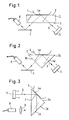
- This identification device contains a transparent glass plate 1 with a first surface 2 and a second surface 3. This glass plate 1 is fixedly arranged so that a finger 4 can be pressed onto its first surface 2.
- the second surface 3 is non-reflective.
- An extensive or large-area light source 5 is used to emit a light beam 6, which is irradiated through the non-reflective wide area 3 into the glass plate 1.
- the light beam 6 is totally reflected on the first surface 2 and then exits through the wide surface 3 to the outside. It first falls on a mirror 7 and is reflected on it in the direction of an image recording device 8, which is a video camera here.
- the video camera 8 is connected to a central processor unit for image processing, a memory for image storage and a monitor for image display.
- the mirror 7 is used to invert the image of the finger 4 so that it can be recorded by the video camera 8 true to the original.
- the captured image is saved and can e.g.
- FIG. 2 A second embodiment of the identification device according to the invention is shown in FIG. 2.
- the transparent glass plate has been replaced by a transparent triangular prism 1.
- the light beam 6 passes through a catheter 3a into the triangular prism 1 a, which, for. B. can be an equilateral or isosceles prism made of glass or a transparent plastic, which has the same optical properties as glass. It is then totally reflected on the hypotenuse of the triangular prism 1 a in the region of the recesses 4 a, the hypotenuse in turn forming the first surface 2 mentioned, against which the finger 4 can be pressed.
- the light beam 6 After total reflection of the light beam 6 at the hypotenuse or base surface 2 of the triangular prism 1, it emerges through the second catheter 3b and is reflected again at the mirror 7 before it hits the image receiving area through the input optics of the video camera 8.
- the light beam 6 preferably runs perpendicular to the cathets 3a and 3b.
- the first surface is the roof surface or cathete 3a of the triangular prism 1 a.
- the light beam 6 coming from the light source 5 thus enters the triangular prism 1 via the base surface or hypotenuse 2 and is first totally in the area of the cavities 4a on the cathete 3a inflected. A further reflection or reflection then takes place on the second cathete 3b before the light leaves the prism 1 through the hypotenuse 2 again. It then strikes the video camera 8 via a suitable optical imaging system 9.
- a mirror 7 for image reversal is no longer required.
- X-Y image distortions and trapezoidal image distortions occur due to the inclination of the totally reflecting surface 3a relative to the optical beam path or light beam 6.
- this image distortion can be corrected electronically with the aid of algorithms, the software required for this being stored in the central processor unit or in the memory connected to it.
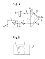
- the embodiment according to FIG. 4 essentially corresponds to the embodiment according to FIG. 3, however, in deviation from FIG. 3, the sensor plane 10 of the video camera 8 and its input optics 9 are tilted relative to the central axis 6a of the light impinging on them.
- the sensor level 10 is, for example, the CCD target device level of the video camera 8.
- the X-Y image distortions and the trapezoidal image distortions can be eliminated.
- the inclination of these elements also solves the depth of field problem caused by the inclination of the total reflection plane or cathete 3a. Any residual distortion can also be corrected electronically here.
- the thumb or finger can also be rolled on the first surface.
- a digitized partial image is generated for each rolling position of the thumb or finger. which is shown in Fig. 5. 5
- an image plane is provided with the reference number 10
- the digitized partial image has the reference number 4b
- the thumb or finger have the reference number 4.
- each partial image 4b e.g. B. is stored in the image memory, that image column is stored in a separate memory area which runs through the center of the respective partial image and which is perpendicular to the rolling direction, which runs in FIG. 5 in the horizontal direction.
- the image column therefore runs in the vertical direction in FIG. 5.
- the center of a partial image 4b can, for. B. lie in the area center.
- a suitable image center point can also be selected to form the partial image center.
- the center of the sub-image 4b is determined by suitable edge finding and average algorithms.
- the image construction is stopped or deleted with the aid of the vertical image columns mentioned when such a change in direction occurs.
- the imaging process must then be repeated. A user can be asked for this by the electronics.
Landscapes
- Engineering & Computer Science (AREA)
- Physics & Mathematics (AREA)
- Health & Medical Sciences (AREA)
- Life Sciences & Earth Sciences (AREA)
- Human Computer Interaction (AREA)
- General Physics & Mathematics (AREA)
- Medical Informatics (AREA)
- Public Health (AREA)
- Biomedical Technology (AREA)
- Heart & Thoracic Surgery (AREA)
- Biophysics (AREA)
- Molecular Biology (AREA)
- Surgery (AREA)
- Animal Behavior & Ethology (AREA)
- General Health & Medical Sciences (AREA)
- Pathology (AREA)
- Veterinary Medicine (AREA)
- Optics & Photonics (AREA)
- Multimedia (AREA)
- Theoretical Computer Science (AREA)
- Measurement Of The Respiration, Hearing Ability, Form, And Blood Characteristics Of Living Organisms (AREA)
- Image Input (AREA)
- Collating Specific Patterns (AREA)
Priority Applications (4)
| Application Number | Priority Date | Filing Date | Title |
|---|---|---|---|
| AT90116698T ATE129396T1 (de) | 1990-08-30 | 1990-08-30 | Identifikationseinrichtung für daumen- oder fingerabdrücke. |
| DE59009822T DE59009822D1 (de) | 1990-08-30 | 1990-08-30 | Identifikationseinrichtung für Daumen- oder Fingerabdrücke. |
| EP90116698A EP0472769B1 (fr) | 1990-08-30 | 1990-08-30 | Dispositif d'identification pour empreintes digitales |
| JP3139062A JP2500876B2 (ja) | 1990-08-30 | 1991-06-11 | 指紋検出装置および方法 |
Applications Claiming Priority (1)
| Application Number | Priority Date | Filing Date | Title |
|---|---|---|---|
| EP90116698A EP0472769B1 (fr) | 1990-08-30 | 1990-08-30 | Dispositif d'identification pour empreintes digitales |
Publications (2)
| Publication Number | Publication Date |
|---|---|
| EP0472769A1 true EP0472769A1 (fr) | 1992-03-04 |
| EP0472769B1 EP0472769B1 (fr) | 1995-10-25 |
Family
ID=8204400
Family Applications (1)
| Application Number | Title | Priority Date | Filing Date |
|---|---|---|---|
| EP90116698A Expired - Lifetime EP0472769B1 (fr) | 1990-08-30 | 1990-08-30 | Dispositif d'identification pour empreintes digitales |
Country Status (4)
| Country | Link |
|---|---|
| EP (1) | EP0472769B1 (fr) |
| JP (1) | JP2500876B2 (fr) |
| AT (1) | ATE129396T1 (fr) |
| DE (1) | DE59009822D1 (fr) |
Cited By (5)
| Publication number | Priority date | Publication date | Assignee | Title |
|---|---|---|---|---|
| DE4429829A1 (de) * | 1993-08-23 | 1995-03-02 | Gim Ges Fuer Innovation Und Ma | Verfahren und Anordnung zur Mustererkennung |
| DE19602380A1 (de) * | 1996-01-24 | 1997-07-31 | Identification Systems Dermalo | Vorrichtung und Verfahren zur verzerrungsfreien Erfassung von Finger- und Handabdrücken |
| ES2142743A1 (es) * | 1997-05-12 | 2000-04-16 | Infos Ingenieria Informatica S | Lector de huellas dactilares perfeccionado |
| EP2039292A4 (fr) * | 2006-07-10 | 2010-01-27 | Pavel Anatolievich Zaytsev | Procede d'enregistrement d'images de dessins papillaires des doigts |
| CN108519325A (zh) * | 2018-05-07 | 2018-09-11 | 河北工业大学 | 一种研究手与物体接触间摩擦系数和接触面积之间关系的方法与装置 |
Families Citing this family (3)
| Publication number | Priority date | Publication date | Assignee | Title |
|---|---|---|---|---|
| US6185319B1 (en) | 1996-12-06 | 2001-02-06 | Yamatake Honeywell Co., Ltd. | Fingerprint input apparatus |
| US6870946B1 (en) | 1998-08-06 | 2005-03-22 | Secugen Corporation | Compact optical fingerprint capturing and recognition system |
| US6381347B1 (en) | 1998-11-12 | 2002-04-30 | Secugen | High contrast, low distortion optical acquistion system for image capturing |
Citations (4)
| Publication number | Priority date | Publication date | Assignee | Title |
|---|---|---|---|---|
| US4120585A (en) * | 1976-11-19 | 1978-10-17 | Calspan Corporation | Fingerprint identification system using a pliable optical prism |
| EP0169496A2 (fr) * | 1984-07-18 | 1986-01-29 | Nec Corporation | Dispositif d'entrée d'images pour le traitement d'une empreinte digitale avant son identification |
| EP0171939A2 (fr) * | 1984-07-18 | 1986-02-19 | Nec Corporation | Dispositif d'entrée d'images |
| EP0361987A1 (fr) * | 1988-03-04 | 1990-04-04 | ETAT FRANCAIS représenté par le Ministre Délégué des Postes et Télécommunications | Dispositif de formation d'une image d'une surface en relief, notamment une empreinte digitale |
Family Cites Families (6)
| Publication number | Priority date | Publication date | Assignee | Title |
|---|---|---|---|---|
| JPS5134680B2 (fr) * | 1971-11-22 | 1976-09-28 | ||
| JPS59204019A (ja) * | 1983-05-06 | 1984-11-19 | Nippon Telegr & Teleph Corp <Ntt> | 凹凸面情報検出装置 |
| JPS60114979A (ja) * | 1984-11-16 | 1985-06-21 | Hitachi Ltd | 指紋入力装置 |
| JPS6368063U (fr) * | 1986-10-20 | 1988-05-07 | ||
| JP2945020B2 (ja) * | 1988-12-28 | 1999-09-06 | 富士通株式会社 | 指紋像入力装置 |
| JP2634656B2 (ja) * | 1988-12-20 | 1997-07-30 | 富士通株式会社 | 指紋像読取り装置 |
-
1990
- 1990-08-30 EP EP90116698A patent/EP0472769B1/fr not_active Expired - Lifetime
- 1990-08-30 AT AT90116698T patent/ATE129396T1/de not_active IP Right Cessation
- 1990-08-30 DE DE59009822T patent/DE59009822D1/de not_active Expired - Fee Related
-
1991
- 1991-06-11 JP JP3139062A patent/JP2500876B2/ja not_active Expired - Lifetime
Patent Citations (4)
| Publication number | Priority date | Publication date | Assignee | Title |
|---|---|---|---|---|
| US4120585A (en) * | 1976-11-19 | 1978-10-17 | Calspan Corporation | Fingerprint identification system using a pliable optical prism |
| EP0169496A2 (fr) * | 1984-07-18 | 1986-01-29 | Nec Corporation | Dispositif d'entrée d'images pour le traitement d'une empreinte digitale avant son identification |
| EP0171939A2 (fr) * | 1984-07-18 | 1986-02-19 | Nec Corporation | Dispositif d'entrée d'images |
| EP0361987A1 (fr) * | 1988-03-04 | 1990-04-04 | ETAT FRANCAIS représenté par le Ministre Délégué des Postes et Télécommunications | Dispositif de formation d'une image d'une surface en relief, notamment une empreinte digitale |
Cited By (6)
| Publication number | Priority date | Publication date | Assignee | Title |
|---|---|---|---|---|
| DE4429829A1 (de) * | 1993-08-23 | 1995-03-02 | Gim Ges Fuer Innovation Und Ma | Verfahren und Anordnung zur Mustererkennung |
| DE19602380A1 (de) * | 1996-01-24 | 1997-07-31 | Identification Systems Dermalo | Vorrichtung und Verfahren zur verzerrungsfreien Erfassung von Finger- und Handabdrücken |
| ES2142743A1 (es) * | 1997-05-12 | 2000-04-16 | Infos Ingenieria Informatica S | Lector de huellas dactilares perfeccionado |
| EP2039292A4 (fr) * | 2006-07-10 | 2010-01-27 | Pavel Anatolievich Zaytsev | Procede d'enregistrement d'images de dessins papillaires des doigts |
| CN108519325A (zh) * | 2018-05-07 | 2018-09-11 | 河北工业大学 | 一种研究手与物体接触间摩擦系数和接触面积之间关系的方法与装置 |
| CN108519325B (zh) * | 2018-05-07 | 2023-08-04 | 河北工业大学 | 一种研究手与物体接触间摩擦系数和接触面积之间关系的方法与装置 |
Also Published As
| Publication number | Publication date |
|---|---|
| JPH05101168A (ja) | 1993-04-23 |
| JP2500876B2 (ja) | 1996-05-29 |
| EP0472769B1 (fr) | 1995-10-25 |
| ATE129396T1 (de) | 1995-11-15 |
| DE59009822D1 (de) | 1995-11-30 |
Similar Documents
| Publication | Publication Date | Title |
|---|---|---|
| DE68926664T2 (de) | Detektoranordnung und Beleuchtungssystem für einen Strichkode-Abtaster mit grosser Tiefenschärfe | |
| DE60023156T2 (de) | Verfahren und gerät zur verminderung der trapezverzerrung und verbesserung der bildschärfe in einem optischen bilderfassungssystem | |
| DE60104146T2 (de) | Flachkamera | |
| DE19581524B4 (de) | Verfahren und System zum Lesen von Bildern ohne Erfordernis einer eigenen Beleuchtungsquelle und Barcodeleser hierfür | |
| CH670752A5 (fr) | ||
| EP0048489A1 (fr) | Dispositif d'examen d'un relief digital | |
| EP1262751A2 (fr) | Dispositif et procédé d'analyse de lumière | |
| EP0472769B1 (fr) | Dispositif d'identification pour empreintes digitales | |
| EP1821064B1 (fr) | Procédé et dispositif destinés à la détection d'un contour d'une surface réfléchissante | |
| DE69835140T2 (de) | Bildlesegerät und fokussierungseinstellungsverfahren dafür | |
| CH688663A5 (de) | Verfahren und Vorrichtung zur Inspektion von Gegenstaenden, insbesondere von Flaschen. | |
| DE3232840A1 (de) | Abtaststrahl-bezugs- und -lese-systeme | |
| DE69725031T2 (de) | Abtaster | |
| DE3424955A1 (de) | Anordnung zum erfassen von fingerpapillaren | |
| EP0223957A1 (fr) | Sonde de balayage opto-électronique | |
| EP0270062B1 (fr) | Dispositif de prise d'image | |
| WO2003098917A1 (fr) | Dispositif et procédé pour échantillonner une maquette | |
| EP0182827A1 (fr) | Dispositif pour donner une image sans distorsion d'un objet situe dans le plan de l'image | |
| WO2003098309A1 (fr) | Dispositif compact permettant la representation anamorphotique de la surface d'objets a l'aide d'un prisme reflechissant | |
| EP1101351A1 (fr) | Tete de scanneur pour le balayage de documents | |
| DE69008579T2 (de) | Vorrichtung zum Feststellen der Richtung des Energiezentrums eines Licht strahlenden Gegenstandes. | |
| DE102022115810A1 (de) | Vorrichtung zur kontaktlosen aufnahme von biometriedaten von hautbereichen | |
| EP1709569B1 (fr) | Dispositif et procede pour la reconnaissance des cretes papillaires | |
| DE69620905T2 (de) | Zielmarke für lasernivelliersysteme | |
| WO2022063741A1 (fr) | Système d'imagerie, en particulier pour une caméra |
Legal Events
| Date | Code | Title | Description |
|---|---|---|---|
| PUAI | Public reference made under article 153(3) epc to a published international application that has entered the european phase |
Free format text: ORIGINAL CODE: 0009012 |
|
| 17P | Request for examination filed |
Effective date: 19910605 |
|
| AK | Designated contracting states |
Kind code of ref document: A1 Designated state(s): AT BE CH DE DK ES FR GB GR IT LI LU NL SE |
|
| 17Q | First examination report despatched |
Effective date: 19941028 |
|
| GRAA | (expected) grant |
Free format text: ORIGINAL CODE: 0009210 |
|
| AK | Designated contracting states |
Kind code of ref document: B1 Designated state(s): AT BE CH DE DK ES FR GB GR IT LI LU NL SE |
|
| PG25 | Lapsed in a contracting state [announced via postgrant information from national office to epo] |
Ref country code: IT Free format text: LAPSE BECAUSE OF FAILURE TO SUBMIT A TRANSLATION OF THE DESCRIPTION OR TO PAY THE FEE WITHIN THE PRESCRIBED TIME-LIMIT;WARNING: LAPSES OF ITALIAN PATENTS WITH EFFECTIVE DATE BEFORE 2007 MAY HAVE OCCURRED AT ANY TIME BEFORE 2007. THE CORRECT EFFECTIVE DATE MAY BE DIFFERENT FROM THE ONE RECORDED. Effective date: 19951025 Ref country code: GR Free format text: LAPSE BECAUSE OF FAILURE TO SUBMIT A TRANSLATION OF THE DESCRIPTION OR TO PAY THE FEE WITHIN THE PRESCRIBED TIME-LIMIT Effective date: 19951025 Ref country code: ES Free format text: THE PATENT HAS BEEN ANNULLED BY A DECISION OF A NATIONAL AUTHORITY Effective date: 19951025 Ref country code: DK Effective date: 19951025 Ref country code: BE Effective date: 19951025 |
|
| REF | Corresponds to: |
Ref document number: 129396 Country of ref document: AT Date of ref document: 19951115 Kind code of ref document: T |
|
| ET | Fr: translation filed | ||
| REF | Corresponds to: |
Ref document number: 59009822 Country of ref document: DE Date of ref document: 19951130 |
|
| GBT | Gb: translation of ep patent filed (gb section 77(6)(a)/1977) |
Effective date: 19951113 |
|
| REG | Reference to a national code |
Ref country code: CH Ref legal event code: NV Representative=s name: A. BRAUN, BRAUN, HERITIER, ESCHMANN AG PATENTANWAE |
|
| PLBE | No opposition filed within time limit |
Free format text: ORIGINAL CODE: 0009261 |
|
| STAA | Information on the status of an ep patent application or granted ep patent |
Free format text: STATUS: NO OPPOSITION FILED WITHIN TIME LIMIT |
|
| PG25 | Lapsed in a contracting state [announced via postgrant information from national office to epo] |
Ref country code: LU Free format text: LAPSE BECAUSE OF NON-PAYMENT OF DUE FEES Effective date: 19960831 |
|
| 26N | No opposition filed | ||
| PGFP | Annual fee paid to national office [announced via postgrant information from national office to epo] |
Ref country code: FR Payment date: 19990803 Year of fee payment: 10 |
|
| PGFP | Annual fee paid to national office [announced via postgrant information from national office to epo] |
Ref country code: SE Payment date: 19990816 Year of fee payment: 10 |
|
| PGFP | Annual fee paid to national office [announced via postgrant information from national office to epo] |
Ref country code: CH Payment date: 19990819 Year of fee payment: 10 |
|
| PGFP | Annual fee paid to national office [announced via postgrant information from national office to epo] |
Ref country code: AT Payment date: 19990824 Year of fee payment: 10 |
|
| PGFP | Annual fee paid to national office [announced via postgrant information from national office to epo] |
Ref country code: GB Payment date: 19990825 Year of fee payment: 10 |
|
| PGFP | Annual fee paid to national office [announced via postgrant information from national office to epo] |
Ref country code: DE Payment date: 19990830 Year of fee payment: 10 |
|
| PGFP | Annual fee paid to national office [announced via postgrant information from national office to epo] |
Ref country code: NL Payment date: 19990831 Year of fee payment: 10 |
|
| PG25 | Lapsed in a contracting state [announced via postgrant information from national office to epo] |
Ref country code: GB Free format text: LAPSE BECAUSE OF NON-PAYMENT OF DUE FEES Effective date: 20000830 Ref country code: AT Free format text: LAPSE BECAUSE OF NON-PAYMENT OF DUE FEES Effective date: 20000830 |
|
| PG25 | Lapsed in a contracting state [announced via postgrant information from national office to epo] |
Ref country code: CH Free format text: LAPSE BECAUSE OF NON-PAYMENT OF DUE FEES Effective date: 20000831 Ref country code: LI Free format text: LAPSE BECAUSE OF NON-PAYMENT OF DUE FEES Effective date: 20000831 Ref country code: SE Free format text: LAPSE BECAUSE OF NON-PAYMENT OF DUE FEES Effective date: 20000831 |
|
| PG25 | Lapsed in a contracting state [announced via postgrant information from national office to epo] |
Ref country code: NL Free format text: LAPSE BECAUSE OF NON-PAYMENT OF DUE FEES Effective date: 20010301 |
|
| REG | Reference to a national code |
Ref country code: CH Ref legal event code: PL |
|
| GBPC | Gb: european patent ceased through non-payment of renewal fee |
Effective date: 20000830 |
|
| EUG | Se: european patent has lapsed |
Ref document number: 90116698.3 |
|
| PG25 | Lapsed in a contracting state [announced via postgrant information from national office to epo] |
Ref country code: FR Free format text: LAPSE BECAUSE OF NON-PAYMENT OF DUE FEES Effective date: 20010430 |
|
| NLV4 | Nl: lapsed or anulled due to non-payment of the annual fee |
Effective date: 20010301 |
|
| PG25 | Lapsed in a contracting state [announced via postgrant information from national office to epo] |
Ref country code: DE Free format text: LAPSE BECAUSE OF NON-PAYMENT OF DUE FEES Effective date: 20010501 |
|
| REG | Reference to a national code |
Ref country code: FR Ref legal event code: ST |