EP0472845A1 - Vantail de porte en verre d'un ascenseur - Google Patents
Vantail de porte en verre d'un ascenseur Download PDFInfo
- Publication number
- EP0472845A1 EP0472845A1 EP91110299A EP91110299A EP0472845A1 EP 0472845 A1 EP0472845 A1 EP 0472845A1 EP 91110299 A EP91110299 A EP 91110299A EP 91110299 A EP91110299 A EP 91110299A EP 0472845 A1 EP0472845 A1 EP 0472845A1
- Authority
- EP
- European Patent Office
- Prior art keywords
- glass
- glass door
- door leaf
- frame
- leaf according
- Prior art date
- Legal status (The legal status is an assumption and is not a legal conclusion. Google has not performed a legal analysis and makes no representation as to the accuracy of the status listed.)
- Granted
Links
- 239000011521 glass Substances 0.000 title claims abstract description 121
- 239000000725 suspension Substances 0.000 claims abstract description 13
- 229910000831 Steel Inorganic materials 0.000 claims description 20
- 239000010959 steel Substances 0.000 claims description 20
- 238000003466 welding Methods 0.000 claims description 7
- 238000005253 cladding Methods 0.000 claims description 5
- 230000001681 protective effect Effects 0.000 claims description 4
- 238000007598 dipping method Methods 0.000 claims 2
- 238000006073 displacement reaction Methods 0.000 abstract description 4
- 230000009191 jumping Effects 0.000 abstract description 2
- 241001247986 Calotropis procera Species 0.000 abstract 1
- 239000002390 adhesive tape Substances 0.000 description 2
- 238000007688 edging Methods 0.000 description 2
- 238000004519 manufacturing process Methods 0.000 description 2
- 239000000463 material Substances 0.000 description 2
- 239000002184 metal Substances 0.000 description 2
- 229910001369 Brass Inorganic materials 0.000 description 1
- 229910000669 Chrome steel Inorganic materials 0.000 description 1
- 206010041662 Splinter Diseases 0.000 description 1
- 239000010951 brass Substances 0.000 description 1
- 239000002131 composite material Substances 0.000 description 1
- 230000000694 effects Effects 0.000 description 1
- 238000005516 engineering process Methods 0.000 description 1
- 238000009434 installation Methods 0.000 description 1
- 238000012544 monitoring process Methods 0.000 description 1
- 239000005336 safety glass Substances 0.000 description 1
- IHQKEDIOMGYHEB-UHFFFAOYSA-M sodium dimethylarsinate Chemical class [Na+].C[As](C)([O-])=O IHQKEDIOMGYHEB-UHFFFAOYSA-M 0.000 description 1
- 125000006850 spacer group Chemical group 0.000 description 1
- 230000000007 visual effect Effects 0.000 description 1
Images



Classifications
-
- B—PERFORMING OPERATIONS; TRANSPORTING
- B66—HOISTING; LIFTING; HAULING
- B66B—ELEVATORS; ESCALATORS OR MOVING WALKWAYS
- B66B13/00—Doors, gates, or other apparatus controlling access to, or exit from, cages or lift well landings
- B66B13/30—Constructional features of doors or gates
- B66B13/303—Details of door panels
-
- E—FIXED CONSTRUCTIONS
- E05—LOCKS; KEYS; WINDOW OR DOOR FITTINGS; SAFES
- E05D—HINGES OR SUSPENSION DEVICES FOR DOORS, WINDOWS OR WINGS
- E05D15/00—Suspension arrangements for wings
- E05D15/06—Suspension arrangements for wings for wings sliding horizontally more or less in their own plane
- E05D15/0621—Details, e.g. suspension or supporting guides
- E05D15/0626—Details, e.g. suspension or supporting guides for wings suspended at the top
-
- E—FIXED CONSTRUCTIONS
- E06—DOORS, WINDOWS, SHUTTERS, OR ROLLER BLINDS IN GENERAL; LADDERS
- E06B—FIXED OR MOVABLE CLOSURES FOR OPENINGS IN BUILDINGS, VEHICLES, FENCES OR LIKE ENCLOSURES IN GENERAL, e.g. DOORS, WINDOWS, BLINDS, GATES
- E06B3/00—Window sashes, door leaves, or like elements for closing wall or like openings; Layout of fixed or moving closures, e.g. windows in wall or like openings; Features of rigidly-mounted outer frames relating to the mounting of wing frames
- E06B3/32—Arrangements of wings characterised by the manner of movement; Arrangements of movable wings in openings; Features of wings or frames relating solely to the manner of movement of the wing
- E06B3/34—Arrangements of wings characterised by the manner of movement; Arrangements of movable wings in openings; Features of wings or frames relating solely to the manner of movement of the wing with only one kind of movement
- E06B3/42—Sliding wings; Details of frames with respect to guiding
- E06B3/46—Horizontally-sliding wings
- E06B3/4636—Horizontally-sliding wings for doors
-
- E—FIXED CONSTRUCTIONS
- E06—DOORS, WINDOWS, SHUTTERS, OR ROLLER BLINDS IN GENERAL; LADDERS
- E06B—FIXED OR MOVABLE CLOSURES FOR OPENINGS IN BUILDINGS, VEHICLES, FENCES OR LIKE ENCLOSURES IN GENERAL, e.g. DOORS, WINDOWS, BLINDS, GATES
- E06B3/00—Window sashes, door leaves, or like elements for closing wall or like openings; Layout of fixed or moving closures, e.g. windows in wall or like openings; Features of rigidly-mounted outer frames relating to the mounting of wing frames
- E06B3/32—Arrangements of wings characterised by the manner of movement; Arrangements of movable wings in openings; Features of wings or frames relating solely to the manner of movement of the wing
- E06B3/34—Arrangements of wings characterised by the manner of movement; Arrangements of movable wings in openings; Features of wings or frames relating solely to the manner of movement of the wing with only one kind of movement
- E06B3/42—Sliding wings; Details of frames with respect to guiding
- E06B3/46—Horizontally-sliding wings
- E06B3/4681—Horizontally-sliding wings made of glass panes without frames
-
- E—FIXED CONSTRUCTIONS
- E06—DOORS, WINDOWS, SHUTTERS, OR ROLLER BLINDS IN GENERAL; LADDERS
- E06B—FIXED OR MOVABLE CLOSURES FOR OPENINGS IN BUILDINGS, VEHICLES, FENCES OR LIKE ENCLOSURES IN GENERAL, e.g. DOORS, WINDOWS, BLINDS, GATES
- E06B3/00—Window sashes, door leaves, or like elements for closing wall or like openings; Layout of fixed or moving closures, e.g. windows in wall or like openings; Features of rigidly-mounted outer frames relating to the mounting of wing frames
- E06B3/54—Fixing of glass panes or like plates
- E06B3/5436—Fixing of glass panes or like plates involving holes or indentations in the pane
-
- E—FIXED CONSTRUCTIONS
- E05—LOCKS; KEYS; WINDOW OR DOOR FITTINGS; SAFES
- E05D—HINGES OR SUSPENSION DEVICES FOR DOORS, WINDOWS OR WINGS
- E05D15/00—Suspension arrangements for wings
- E05D15/06—Suspension arrangements for wings for wings sliding horizontally more or less in their own plane
- E05D15/0621—Details, e.g. suspension or supporting guides
- E05D15/0626—Details, e.g. suspension or supporting guides for wings suspended at the top
- E05D15/0656—Bottom guides
-
- E—FIXED CONSTRUCTIONS
- E05—LOCKS; KEYS; WINDOW OR DOOR FITTINGS; SAFES
- E05Y—INDEXING SCHEME ASSOCIATED WITH SUBCLASSES E05D AND E05F, RELATING TO CONSTRUCTION ELEMENTS, ELECTRIC CONTROL, POWER SUPPLY, POWER SIGNAL OR TRANSMISSION, USER INTERFACES, MOUNTING OR COUPLING, DETAILS, ACCESSORIES, AUXILIARY OPERATIONS NOT OTHERWISE PROVIDED FOR, APPLICATION THEREOF
- E05Y2201/00—Constructional elements; Accessories therefor
- E05Y2201/60—Suspension or transmission members; Accessories therefor
- E05Y2201/622—Suspension or transmission members elements
- E05Y2201/638—Cams; Ramps
-
- E—FIXED CONSTRUCTIONS
- E05—LOCKS; KEYS; WINDOW OR DOOR FITTINGS; SAFES
- E05Y—INDEXING SCHEME ASSOCIATED WITH SUBCLASSES E05D AND E05F, RELATING TO CONSTRUCTION ELEMENTS, ELECTRIC CONTROL, POWER SUPPLY, POWER SIGNAL OR TRANSMISSION, USER INTERFACES, MOUNTING OR COUPLING, DETAILS, ACCESSORIES, AUXILIARY OPERATIONS NOT OTHERWISE PROVIDED FOR, APPLICATION THEREOF
- E05Y2600/00—Mounting or coupling arrangements for elements provided for in this subclass
- E05Y2600/10—Adjustable
- E05Y2600/20—Adjustable with specific transmission movement
-
- E—FIXED CONSTRUCTIONS
- E05—LOCKS; KEYS; WINDOW OR DOOR FITTINGS; SAFES
- E05Y—INDEXING SCHEME ASSOCIATED WITH SUBCLASSES E05D AND E05F, RELATING TO CONSTRUCTION ELEMENTS, ELECTRIC CONTROL, POWER SUPPLY, POWER SIGNAL OR TRANSMISSION, USER INTERFACES, MOUNTING OR COUPLING, DETAILS, ACCESSORIES, AUXILIARY OPERATIONS NOT OTHERWISE PROVIDED FOR, APPLICATION THEREOF
- E05Y2800/00—Details, accessories and auxiliary operations not otherwise provided for
- E05Y2800/67—Materials; Strength alteration thereof
- E05Y2800/672—Glass
-
- E—FIXED CONSTRUCTIONS
- E05—LOCKS; KEYS; WINDOW OR DOOR FITTINGS; SAFES
- E05Y—INDEXING SCHEME ASSOCIATED WITH SUBCLASSES E05D AND E05F, RELATING TO CONSTRUCTION ELEMENTS, ELECTRIC CONTROL, POWER SUPPLY, POWER SIGNAL OR TRANSMISSION, USER INTERFACES, MOUNTING OR COUPLING, DETAILS, ACCESSORIES, AUXILIARY OPERATIONS NOT OTHERWISE PROVIDED FOR, APPLICATION THEREOF
- E05Y2900/00—Application of doors, windows, wings or fittings thereof
- E05Y2900/10—Application of doors, windows, wings or fittings thereof for buildings or parts thereof
- E05Y2900/104—Application of doors, windows, wings or fittings thereof for buildings or parts thereof for elevators
Definitions
- the invention relates to a glass door leaf with a smooth surface on the user side for elevators.
- a disadvantage of the known device is that a complex manufacturing process with high manufacturing costs for the glass pane is necessary.
- Another disadvantage is that glass panes clamped on oblique edges tend to be more susceptible to breakage when subjected to force.
- the invention seeks to remedy this.
- the invention as characterized in the claims, solves the problem of avoiding the disadvantages of the known device and proposing elevator doors with glass as the material, which meet the requirements of today's safety regulations with regard to resilience.
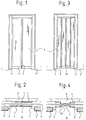
- 1 denotes an elevator entrance / exit, which is delimited by masonry 2 and door jamb 3.
- Shaft doors forming glass door 4 close the Input / output 1 from.
- An elevator car 6 guided in a shaft 5 is closed by car doors formed by glass door leaves 4.
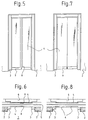
- the glass door leaves 4 have steel edge strips 7 or glass edge strips 8 in the closing area and lower skirting strips 9 on the lower narrow side.
- Narrow glass door leaves 4 are enclosed by frame 10 for reasons of strength.
- the cladding of the steel edge strips 7 or frame 10 are made of chrome steel, sheet steel, anodized light metal or polished brass, depending on the visual appearance requirements.
- a glass door leaf 4 with a steel edge strip 7 is shown as a variant.
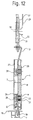
- a glass pane 11 is connected to a guide shoe plate 12 on its lower narrow side and to a suspension bracket 13 on its upper narrow side.
- the steel edge strip 7 arranged on the broad side in the closing area is held by a lower strip support 14 and by an upper strip support 15.
- a holding plate 16 is arranged on the guide shoe plate 12, on which a closing spring engages.
- the glass pane 11 is held at the lower end between the lower skirting board 9 and a glass retaining bar 24 of the guide shoe plate 12 and at the upper end between an upper skirting board 20 and the suspension bracket 13.
- double-sided adhesive tape is provided on the contact surfaces between glass and metal.
- Rubber bushings 21 let into bores in the glass pane 11 comprise fastening nuts 22 inserted on the shaft side, which are connected to the skirting boards 9; 20 arranged welding bolts 23 stand.
- the glass door leaf 4 On the shaft side, the glass door leaf 4 has a lower cover 26 at the lower end and an upper cover 27 at the upper end, which are held on the fastening nuts 22 by means of screws 28.
- a carrier 29 holds a guide rail 30 which is arranged along the displacement path and on which rollers 31 carrying the glass door leaf 4 travel and which are connected to the suspension bracket 13 by means of screw bolts engaging in elongated holes 32.
- An elevated collar 33 arranged on the roller 31 ensures secure guidance and prevents the glass door leaf 4 from jumping out of the guide rail 30.
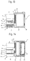
- FIG. 13 and 14 show a composite safety glass pane 11 consisting of a first glass layer 34 and a second glass layer 35, which are connected by means of a film 36, which is damaged when the glass layers 34; 35 has a splinter binding effect.
- the film 36 is used for decorative purposes in that tinted and / or illustrated glass door panels can be made with transparently colored and / or patterned films.
- the holes in which the rubber bushings 21 are inserted are made for technical reasons per glass layer 34; 35 attached.
- the first glass layer 34 is then joined together with the second glass layer 35, which leads to inequality of the holes.
- the steel edge strip 7 ensures a minimum width at the wing edge in accordance with the regulations in the closing area and also enables the arrangement of a person detector 37 on the wing edge.
- the steel edge strip 7 of a glass door leaf 4 forming a shaft door consists of a front protective profile 38 and a rear protective profile 39 which surround a wide edge strip 40 and are connected to the latter by means of double-sided adhesive tape 41.
- a spacer plate 42 provides the necessary depth adjustment.
- the steel edge strip 7 of a glass door leaf 4 forming a cabin door consists of a U-shaped cladding profile 43 which surrounds a narrow edge strip 44 and saves space for the person detector 37.
- a shielding plate 45 is provided between the narrow edge strip 44 and the person detector 37.
- a glass door leaf 4 with a glass pane 11 carried by a frame 10 is shown as a variant.
- frame supports 46 are arranged, which are connected at the lower end of the glass door leaf 4 to the glass retaining strip 24 and to the guide shoe strip 25 and at the upper end of the glass door leaf 4 to the suspension bracket 13.
- the covers 26; 27 are fastened with countersunk screws 47 for reasons of space.
- the other fasteners correspond to those of the variant with steel edging.
- a frame strip 48 arranged on the frame support 46 is enclosed by a frame profile 49.
- the edge in the closing area is instead of Frame bar 48, a frame plate 50 is provided, which is surrounded by a U-shaped frame cladding 51 with a U-shaped recess accommodating the person detector 37.
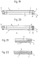
- a glass door leaf 4 with a glass edge strip 8 is shown as a variant.
- a glass edge strip 8 glued onto the glass pane 11 is provided on the edge lying in the closing area in order to maintain the correct edge width.
- the fastening means at the lower and upper end of the glass door leaf 4 correspond to those of the variant with a steel edge strip.
- a person detector arranged between the car door and the shaft door is provided for monitoring the door area.
- a glass door leaf 4 without an edge strip is shown as an embodiment variant.
- the edge width specified by the thickness of the glass pane is below the minimum width required by the regulations.
- the closing force caused by the door drive is reduced in accordance with the reduced edge width.
- an L-shaped guide shoe plate 12 with a glass retaining strip 24 and guide shoe strip 25 is used instead of the T-shaped guide shoe plate 12.
- fastening nuts 22 with semicircular heads are used.
- the glass pane 11 is held between the suspension bracket 13 arranged on the user side and a glass holding plate 52 arranged on the shaft side with welding bolts 23.
Landscapes
- Engineering & Computer Science (AREA)
- Civil Engineering (AREA)
- Structural Engineering (AREA)
- Mechanical Engineering (AREA)
- Window Of Vehicle (AREA)
- Elevator Door Apparatuses (AREA)
- Support Devices For Sliding Doors (AREA)
- Securing Of Glass Panes Or The Like (AREA)
Applications Claiming Priority (2)
| Application Number | Priority Date | Filing Date | Title |
|---|---|---|---|
| CH2633/90 | 1990-08-14 | ||
| CH263390 | 1990-08-14 |
Publications (2)
| Publication Number | Publication Date |
|---|---|
| EP0472845A1 true EP0472845A1 (fr) | 1992-03-04 |
| EP0472845B1 EP0472845B1 (fr) | 1995-01-11 |
Family
ID=4238153
Family Applications (1)
| Application Number | Title | Priority Date | Filing Date |
|---|---|---|---|
| EP91110299A Expired - Lifetime EP0472845B1 (fr) | 1990-08-14 | 1991-06-22 | Vantail de porte en verre d'un ascenseur |
Country Status (8)
| Country | Link |
|---|---|
| US (1) | US5139111A (fr) |
| EP (1) | EP0472845B1 (fr) |
| JP (1) | JPH04251089A (fr) |
| AT (1) | ATE116945T1 (fr) |
| CA (1) | CA2045854A1 (fr) |
| DE (1) | DE59104217D1 (fr) |
| ES (1) | ES2069779T3 (fr) |
| HK (1) | HK69696A (fr) |
Cited By (3)
| Publication number | Priority date | Publication date | Assignee | Title |
|---|---|---|---|---|
| EP0600756A1 (fr) * | 1992-12-04 | 1994-06-08 | Otis Elevator Company | Structure de porte pour ascenseur |
| EP1099823A3 (fr) * | 1999-11-10 | 2003-07-02 | AMFT Ritschel GmbH | Feuille de cadre |
| EP3379907A1 (fr) * | 2017-03-21 | 2018-09-26 | Schneider Electric IT Corporation | Système de porte pneumatique à deux vantaux sans rail au sol dans la porte pour le confinement d'allées de centre de données |
Families Citing this family (17)
| Publication number | Priority date | Publication date | Assignee | Title |
|---|---|---|---|---|
| US5673770A (en) * | 1996-01-25 | 1997-10-07 | Friedman; Harold S. | Sliding door assembly for an elevator and method of installing same |
| IT1285848B1 (it) * | 1996-04-22 | 1998-06-24 | Kone Oy | Soglia per una porta di pianerottolo per un elevatore. |
| FI101064B (fi) * | 1996-05-28 | 1998-04-15 | Kone Oy | Hissikorin kynnysjärjestely |
| DE10052539B4 (de) * | 2000-10-23 | 2004-09-30 | Dorma Gmbh + Co. Kg | Aus mehreren Schiebeflügeln gebildete Schiebewand |
| JP4959126B2 (ja) * | 2004-10-22 | 2012-06-20 | オーチス エレベータ カンパニー | エレベーターの扉装置 |
| JP2007008602A (ja) * | 2005-06-28 | 2007-01-18 | Mitsubishi Electric Corp | エレベータのドア装置 |
| ITMI20050343U1 (it) * | 2005-10-03 | 2007-04-04 | Sematic Italia Spa | Dispositivo di sicurezza per porte di ascensori |
| KR101027873B1 (ko) * | 2008-12-16 | 2011-04-07 | 윤일식 | 엘리베이터 도어의 유리판 고정장치 |
| CN101863409B (zh) * | 2010-06-02 | 2015-08-12 | 江南嘉捷电梯股份有限公司 | 电梯用玻璃层门 |
| FI20116266L (fi) * | 2011-12-13 | 2013-06-14 | Kone Corp | Eristetty hissin tason ovi |
| JP6628281B2 (ja) * | 2016-03-14 | 2020-01-08 | 司ゴム電材株式会社 | エレベータのドアシュー及びエレベータドア |
| US10683697B2 (en) | 2018-06-08 | 2020-06-16 | Ep Acquisition, Inc. | Fire-rated sliding glass elevator door |
| KR102023142B1 (ko) * | 2019-03-26 | 2019-09-19 | 주식회사 하이에코 | 개량형 조립식레일을 갖는 창호틀 |
| US11512524B1 (en) | 2019-07-22 | 2022-11-29 | Ep Acquisition, Inc. | Fire-rated elevator door frame and transom flush with door |
| RU197839U1 (ru) * | 2019-12-26 | 2020-06-02 | Общество с ограниченной ответственностью "МЛК" | Створка лифта |
| CN111779390B (zh) * | 2020-07-10 | 2022-02-22 | 中车青岛四方机车车辆股份有限公司 | 一种淋浴房合页及轨道列车 |
| US11873193B1 (en) * | 2023-01-20 | 2024-01-16 | Otis Elevator Company | Elevator door systems with minimum running clearance |
Citations (6)
| Publication number | Priority date | Publication date | Assignee | Title |
|---|---|---|---|---|
| CH430146A (de) * | 1965-04-22 | 1967-02-15 | Temperit Ag | Am unteren oberen Wand- oder Türrand befestigbare Leiste, insbesondere bei Türen oder Wänden aus Glas |
| US3796405A (en) * | 1972-10-16 | 1974-03-12 | Work Right Prod Inc | Roller bracket |
| US4051633A (en) * | 1976-06-01 | 1977-10-04 | Voegele Jr William P | Top hung sliding window assembly |
| GB2016569A (en) * | 1978-02-08 | 1979-09-26 | Marinoni & Figli Casma | Device for mounting a sheet member |
| DE3601890A1 (de) * | 1986-01-23 | 1987-07-30 | Geze Gmbh | Beschlag fuer glastueren od.dgl. |
| US4769949A (en) * | 1987-05-26 | 1988-09-13 | Usg Industries, Inc. | Tub and shower door enclosure having free-floating self-adjusting lower guide assembly |
Family Cites Families (3)
| Publication number | Priority date | Publication date | Assignee | Title |
|---|---|---|---|---|
| US4324373A (en) * | 1979-11-19 | 1982-04-13 | Ppg Industries, Inc. | Method and apparatus for add-on reinforcement for transparency system for crew module for aircraft |
| US4530189A (en) * | 1983-04-25 | 1985-07-23 | Westinghouse Electric Corp. | Door entrance |
| US4905432A (en) * | 1988-03-03 | 1990-03-06 | Navistar International Transportation Corp. | Windshield glass and trim assembly and method for making same |
-
1991
- 1991-06-22 DE DE59104217T patent/DE59104217D1/de not_active Expired - Fee Related
- 1991-06-22 ES ES91110299T patent/ES2069779T3/es not_active Expired - Lifetime
- 1991-06-22 AT AT91110299T patent/ATE116945T1/de not_active IP Right Cessation
- 1991-06-22 EP EP91110299A patent/EP0472845B1/fr not_active Expired - Lifetime
- 1991-06-27 CA CA002045854A patent/CA2045854A1/fr not_active Abandoned
- 1991-08-13 JP JP3202973A patent/JPH04251089A/ja active Pending
- 1991-08-13 US US07/744,259 patent/US5139111A/en not_active Expired - Fee Related
-
1996
- 1996-04-18 HK HK69696A patent/HK69696A/xx not_active IP Right Cessation
Patent Citations (6)
| Publication number | Priority date | Publication date | Assignee | Title |
|---|---|---|---|---|
| CH430146A (de) * | 1965-04-22 | 1967-02-15 | Temperit Ag | Am unteren oberen Wand- oder Türrand befestigbare Leiste, insbesondere bei Türen oder Wänden aus Glas |
| US3796405A (en) * | 1972-10-16 | 1974-03-12 | Work Right Prod Inc | Roller bracket |
| US4051633A (en) * | 1976-06-01 | 1977-10-04 | Voegele Jr William P | Top hung sliding window assembly |
| GB2016569A (en) * | 1978-02-08 | 1979-09-26 | Marinoni & Figli Casma | Device for mounting a sheet member |
| DE3601890A1 (de) * | 1986-01-23 | 1987-07-30 | Geze Gmbh | Beschlag fuer glastueren od.dgl. |
| US4769949A (en) * | 1987-05-26 | 1988-09-13 | Usg Industries, Inc. | Tub and shower door enclosure having free-floating self-adjusting lower guide assembly |
Cited By (4)
| Publication number | Priority date | Publication date | Assignee | Title |
|---|---|---|---|---|
| EP0600756A1 (fr) * | 1992-12-04 | 1994-06-08 | Otis Elevator Company | Structure de porte pour ascenseur |
| EP1099823A3 (fr) * | 1999-11-10 | 2003-07-02 | AMFT Ritschel GmbH | Feuille de cadre |
| EP3379907A1 (fr) * | 2017-03-21 | 2018-09-26 | Schneider Electric IT Corporation | Système de porte pneumatique à deux vantaux sans rail au sol dans la porte pour le confinement d'allées de centre de données |
| US10465431B2 (en) | 2017-03-21 | 2019-11-05 | Schneider Electric It Corporation | Pneumatic bi-parting door system without a floor track in the doorway for data center aisle containment |
Also Published As
| Publication number | Publication date |
|---|---|
| JPH04251089A (ja) | 1992-09-07 |
| DE59104217D1 (de) | 1995-02-23 |
| ES2069779T3 (es) | 1995-05-16 |
| ATE116945T1 (de) | 1995-01-15 |
| CA2045854A1 (fr) | 1992-02-15 |
| HK69696A (en) | 1996-04-26 |
| EP0472845B1 (fr) | 1995-01-11 |
| US5139111A (en) | 1992-08-18 |
Similar Documents
| Publication | Publication Date | Title |
|---|---|---|
| EP0472845B1 (fr) | Vantail de porte en verre d'un ascenseur | |
| WO2008074167A1 (fr) | Cabine d'ascenseur équipée d'une fenêtre de maintenance | |
| WO2010079125A1 (fr) | Système de profilés pour porte coulissante | |
| CH674875A5 (fr) | ||
| DE10021330A1 (de) | Verstellbare Scharnier-Rahmen-Anordnung | |
| EP0400291A1 (fr) | Panneau frontal pour meubles | |
| EP0114412B1 (fr) | Cadre dormant pour fenêtres ou portes avec coffre superposable pour volet roulant ou similaire | |
| CH651100A5 (de) | Scharnier zur beweglichen verankerung von tueren und fenstern. | |
| DE102004007568B4 (de) | Vorrichtung zur hängenden Anordnung einer Sicherheitsglasscheibe an einem Trägerprofil | |
| EP3527767A1 (fr) | Élément coulissant basculant | |
| DE2700648C3 (de) | Aus einem Spiegel, einer Glasscheibe oder einem ähnlichen Material bestehende Schiebetür | |
| DE29507125U1 (de) | Tür aus selbsttragendem Strukturglas | |
| DE10023761A1 (de) | Aufliegender Türantrieb | |
| DE10023762C2 (de) | Beschlag für einen Glasflügel | |
| DE19960686C2 (de) | Justierbares Band | |
| AT521503A4 (de) | Holz-Aluminium-Fenster | |
| EP2604782A1 (fr) | Profilé de battant de fenêtre pour le montage de cales ou analogue | |
| EP1375802B1 (fr) | Porte coupe-feu vitrée avec couverture pour charnière de porte | |
| EP0371348A1 (fr) | Ecran pour douche | |
| DE2844482C3 (de) | Dachfenster | |
| EP1258592B1 (fr) | Entrée reculée d'une magasin avec vitrage anti-feu | |
| DE202012004616U1 (de) | Fenster, Tür oder dergleichen mit mindestens einem Kantel | |
| EP3527768A1 (fr) | Agencement pour un élément pivotant-coulissant | |
| DE2501759A1 (de) | Umkleidekabinensystem aus vorgespanntem glas | |
| DE8528920U1 (de) | Türblatt inkl. Halterung |
Legal Events
| Date | Code | Title | Description |
|---|---|---|---|
| PUAI | Public reference made under article 153(3) epc to a published international application that has entered the european phase |
Free format text: ORIGINAL CODE: 0009012 |
|
| AK | Designated contracting states |
Kind code of ref document: A1 Designated state(s): AT BE CH DE ES FR GB IT LI NL SE |
|
| 17P | Request for examination filed |
Effective date: 19920818 |
|
| 17Q | First examination report despatched |
Effective date: 19940322 |
|
| GRAA | (expected) grant |
Free format text: ORIGINAL CODE: 0009210 |
|
| AK | Designated contracting states |
Kind code of ref document: B1 Designated state(s): AT BE CH DE ES FR GB IT LI NL SE |
|
| REF | Corresponds to: |
Ref document number: 116945 Country of ref document: AT Date of ref document: 19950115 Kind code of ref document: T |
|
| REF | Corresponds to: |
Ref document number: 59104217 Country of ref document: DE Date of ref document: 19950223 |
|
| GBT | Gb: translation of ep patent filed (gb section 77(6)(a)/1977) |
Effective date: 19950210 |
|
| ET | Fr: translation filed | ||
| ITF | It: translation for a ep patent filed | ||
| REG | Reference to a national code |
Ref country code: ES Ref legal event code: FG2A Ref document number: 2069779 Country of ref document: ES Kind code of ref document: T3 |
|
| PLBE | No opposition filed within time limit |
Free format text: ORIGINAL CODE: 0009261 |
|
| STAA | Information on the status of an ep patent application or granted ep patent |
Free format text: STATUS: NO OPPOSITION FILED WITHIN TIME LIMIT |
|
| 26N | No opposition filed | ||
| PGFP | Annual fee paid to national office [announced via postgrant information from national office to epo] |
Ref country code: SE Payment date: 19980507 Year of fee payment: 8 |
|
| PGFP | Annual fee paid to national office [announced via postgrant information from national office to epo] |
Ref country code: BE Payment date: 19980518 Year of fee payment: 8 |
|
| PGFP | Annual fee paid to national office [announced via postgrant information from national office to epo] |
Ref country code: GB Payment date: 19980520 Year of fee payment: 8 Ref country code: DE Payment date: 19980520 Year of fee payment: 8 |
|
| PGFP | Annual fee paid to national office [announced via postgrant information from national office to epo] |
Ref country code: FR Payment date: 19980522 Year of fee payment: 8 Ref country code: AT Payment date: 19980522 Year of fee payment: 8 |
|
| PGFP | Annual fee paid to national office [announced via postgrant information from national office to epo] |
Ref country code: ES Payment date: 19980615 Year of fee payment: 8 |
|
| PGFP | Annual fee paid to national office [announced via postgrant information from national office to epo] |
Ref country code: NL Payment date: 19980630 Year of fee payment: 8 |
|
| PGFP | Annual fee paid to national office [announced via postgrant information from national office to epo] |
Ref country code: CH Payment date: 19980921 Year of fee payment: 8 |
|
| PG25 | Lapsed in a contracting state [announced via postgrant information from national office to epo] |
Ref country code: GB Free format text: LAPSE BECAUSE OF NON-PAYMENT OF DUE FEES Effective date: 19990622 Ref country code: AT Free format text: LAPSE BECAUSE OF NON-PAYMENT OF DUE FEES Effective date: 19990622 |
|
| PG25 | Lapsed in a contracting state [announced via postgrant information from national office to epo] |
Ref country code: ES Free format text: THE PATENT HAS BEEN ANNULLED BY A DECISION OF A NATIONAL AUTHORITY Effective date: 19990623 |
|
| PG25 | Lapsed in a contracting state [announced via postgrant information from national office to epo] |
Ref country code: SE Free format text: THE PATENT HAS BEEN ANNULLED BY A DECISION OF A NATIONAL AUTHORITY Effective date: 19990629 |
|
| PG25 | Lapsed in a contracting state [announced via postgrant information from national office to epo] |
Ref country code: LI Free format text: LAPSE BECAUSE OF NON-PAYMENT OF DUE FEES Effective date: 19990630 Ref country code: FR Free format text: THE PATENT HAS BEEN ANNULLED BY A DECISION OF A NATIONAL AUTHORITY Effective date: 19990630 Ref country code: CH Free format text: LAPSE BECAUSE OF NON-PAYMENT OF DUE FEES Effective date: 19990630 Ref country code: BE Free format text: LAPSE BECAUSE OF NON-PAYMENT OF DUE FEES Effective date: 19990630 |
|
| BERE | Be: lapsed |
Owner name: INVENTIO A.G. Effective date: 19990630 |
|
| PG25 | Lapsed in a contracting state [announced via postgrant information from national office to epo] |
Ref country code: NL Free format text: LAPSE BECAUSE OF NON-PAYMENT OF DUE FEES Effective date: 20000101 |
|
| GBPC | Gb: european patent ceased through non-payment of renewal fee |
Effective date: 19990622 |
|
| REG | Reference to a national code |
Ref country code: CH Ref legal event code: PL |
|
| EUG | Se: european patent has lapsed |
Ref document number: 91110299.4 |
|
| NLV4 | Nl: lapsed or anulled due to non-payment of the annual fee |
Effective date: 20000101 |
|
| PG25 | Lapsed in a contracting state [announced via postgrant information from national office to epo] |
Ref country code: DE Free format text: LAPSE BECAUSE OF NON-PAYMENT OF DUE FEES Effective date: 20000503 |
|
| REG | Reference to a national code |
Ref country code: FR Ref legal event code: ST |
|
| REG | Reference to a national code |
Ref country code: ES Ref legal event code: FD2A Effective date: 20020204 |
|
| PG25 | Lapsed in a contracting state [announced via postgrant information from national office to epo] |
Ref country code: IT Free format text: LAPSE BECAUSE OF NON-PAYMENT OF DUE FEES;WARNING: LAPSES OF ITALIAN PATENTS WITH EFFECTIVE DATE BEFORE 2007 MAY HAVE OCCURRED AT ANY TIME BEFORE 2007. THE CORRECT EFFECTIVE DATE MAY BE DIFFERENT FROM THE ONE RECORDED. Effective date: 20050622 |