EP3527767A1 - Élément coulissant basculant - Google Patents
Élément coulissant basculant Download PDFInfo
- Publication number
- EP3527767A1 EP3527767A1 EP19151202.9A EP19151202A EP3527767A1 EP 3527767 A1 EP3527767 A1 EP 3527767A1 EP 19151202 A EP19151202 A EP 19151202A EP 3527767 A1 EP3527767 A1 EP 3527767A1
- Authority
- EP
- European Patent Office
- Prior art keywords
- lifting
- sash
- wing
- profile
- plane
- Prior art date
- Legal status (The legal status is an assumption and is not a legal conclusion. Google has not performed a legal analysis and makes no representation as to the accuracy of the status listed.)
- Granted
Links
Images

Classifications
-
- E—FIXED CONSTRUCTIONS
- E06—DOORS, WINDOWS, SHUTTERS, OR ROLLER BLINDS IN GENERAL; LADDERS
- E06B—FIXED OR MOVABLE CLOSURES FOR OPENINGS IN BUILDINGS, VEHICLES, FENCES OR LIKE ENCLOSURES IN GENERAL, e.g. DOORS, WINDOWS, BLINDS, GATES
- E06B1/00—Border constructions of openings in walls, floors, or ceilings; Frames to be rigidly mounted in such openings
- E06B1/70—Sills; Thresholds
-
- E—FIXED CONSTRUCTIONS
- E05—LOCKS; KEYS; WINDOW OR DOOR FITTINGS; SAFES
- E05D—HINGES OR SUSPENSION DEVICES FOR DOORS, WINDOWS OR WINGS
- E05D15/00—Suspension arrangements for wings
- E05D15/56—Suspension arrangements for wings with successive different movements
- E05D15/565—Suspension arrangements for wings with successive different movements for raising wings before sliding
-
- E—FIXED CONSTRUCTIONS
- E06—DOORS, WINDOWS, SHUTTERS, OR ROLLER BLINDS IN GENERAL; LADDERS
- E06B—FIXED OR MOVABLE CLOSURES FOR OPENINGS IN BUILDINGS, VEHICLES, FENCES OR LIKE ENCLOSURES IN GENERAL, e.g. DOORS, WINDOWS, BLINDS, GATES
- E06B3/00—Window sashes, door leaves, or like elements for closing wall or like openings; Layout of fixed or moving closures, e.g. windows in wall or like openings; Features of rigidly-mounted outer frames relating to the mounting of wing frames
- E06B3/32—Arrangements of wings characterised by the manner of movement; Arrangements of movable wings in openings; Features of wings or frames relating solely to the manner of movement of the wing
- E06B3/34—Arrangements of wings characterised by the manner of movement; Arrangements of movable wings in openings; Features of wings or frames relating solely to the manner of movement of the wing with only one kind of movement
- E06B3/42—Sliding wings; Details of frames with respect to guiding
- E06B3/46—Horizontally-sliding wings
- E06B3/4609—Horizontally-sliding wings for windows
-
- E—FIXED CONSTRUCTIONS
- E06—DOORS, WINDOWS, SHUTTERS, OR ROLLER BLINDS IN GENERAL; LADDERS
- E06B—FIXED OR MOVABLE CLOSURES FOR OPENINGS IN BUILDINGS, VEHICLES, FENCES OR LIKE ENCLOSURES IN GENERAL, e.g. DOORS, WINDOWS, BLINDS, GATES
- E06B3/00—Window sashes, door leaves, or like elements for closing wall or like openings; Layout of fixed or moving closures, e.g. windows in wall or like openings; Features of rigidly-mounted outer frames relating to the mounting of wing frames
- E06B3/32—Arrangements of wings characterised by the manner of movement; Arrangements of movable wings in openings; Features of wings or frames relating solely to the manner of movement of the wing
- E06B3/50—Arrangements of wings characterised by the manner of movement; Arrangements of movable wings in openings; Features of wings or frames relating solely to the manner of movement of the wing with more than one kind of movement
- E06B3/52—Wings requiring lifting before opening
-
- E—FIXED CONSTRUCTIONS
- E05—LOCKS; KEYS; WINDOW OR DOOR FITTINGS; SAFES
- E05D—HINGES OR SUSPENSION DEVICES FOR DOORS, WINDOWS OR WINGS
- E05D15/00—Suspension arrangements for wings
- E05D15/06—Suspension arrangements for wings for wings sliding horizontally more or less in their own plane
- E05D15/0621—Details, e.g. suspension or supporting guides
- E05D15/066—Details, e.g. suspension or supporting guides for wings supported at the bottom
- E05D15/0686—Tracks
-
- E—FIXED CONSTRUCTIONS
- E05—LOCKS; KEYS; WINDOW OR DOOR FITTINGS; SAFES
- E05Y—INDEXING SCHEME ASSOCIATED WITH SUBCLASSES E05D AND E05F, RELATING TO CONSTRUCTION ELEMENTS, ELECTRIC CONTROL, POWER SUPPLY, POWER SIGNAL OR TRANSMISSION, USER INTERFACES, MOUNTING OR COUPLING, DETAILS, ACCESSORIES, AUXILIARY OPERATIONS NOT OTHERWISE PROVIDED FOR, APPLICATION THEREOF
- E05Y2900/00—Application of doors, windows, wings or fittings thereof
- E05Y2900/10—Application of doors, windows, wings or fittings thereof for buildings or parts thereof
- E05Y2900/13—Type of wing
- E05Y2900/132—Doors
Definitions
- the present invention relates to a lift-and-slide member, in particular a lift-and-slide door or a lift-and-slide window, comprising a track which includes a track and surface areas adjacent both sides of the track, and a track which is movable on the track by means of a track and between a lowered track Fixing position and a raised displacement position is adjustable, wherein the wing has a sash profile and a glass element held by this and defines a wing plane, wherein the lifting sliding element comprises a bottom sill, which defines a ground plane, and wherein the sash profile has a bottom on which a Support surface is formed, which can be placed on the threshold when moving the wing from the raised displacement position in the lowered fixing position.
- Such lifting slide elements find, for example in the form of large patio doors or windows increasing popularity.
- the wing sits immovably on the threshold when it is in the lowered fixing position.
- the wing can be moved manually or by motor when it is in the raised position.
- the raising and lowering of the wing can be done by operating a handle, which is coupled via a fitting gear with a lifting mechanism.
- the sash profile is at least partially made of a fiber composite material, such as a glass fiber reinforced plastic, and has a cross-sectional shape in which the ratio of measured parallel to the wing plane width of the sash profile to the measured perpendicular to the wing plane depth of the sash profile 0.9 or less, and that the running rail is lowered relative to the ground plane, that at least the adjacent to the raceway surface areas of the running rail are arranged below the ground plane.
- a fiber composite material such as a glass fiber reinforced plastic
- a sash profile of fiber composite material in particular of glass fiber reinforced plastic (GRP) has a particularly high strength. Measured in the fiber direction similar tensile strength values are achieved as in steel. The fact that the ratio of the profile width to the tread depth is 0.9 or less, the sash profile appears relatively narrow when viewed from the side and thus unobtrusive. The relatively large tread depth ensures sufficient stability.
- GRP glass fiber reinforced plastic
- a particular advantage of the use of fiber composite material for the production of door or window profiles is its low thermal conductivity. Furthermore, the color design of sash profiles made of fiber composite material is simplified because z. B. glass fiber reinforced plastics can make chemical compounds with paints.
- An inventive lifting slide element is simple and inexpensive to produce.
- the fiberglass profile to be manufactured from fiber composite material can be processed with conventional machines, as are common in joinery or plastic window manufacturing.
- An embodiment of the invention provides that the running rail is attached to the ground sill or in particular integrally formed.
- the threshold may in this case be designed in particular for direct placement of the wing.
- the sash profile is at least partially made of a glass fiber reinforced plastic.
- the roller assembly When mounted lifting slide element, the roller assembly can withstand both the raised wing and lowered wing opposite the support surface down or be flush with it.
- the invention is based in particular on the finding that a narrow sash profile, which is made of fiber composite material and also has a projecting from the profile roller arrangement, all requirements for stability, thermal insulation and design, which are in modern lift-slide elements, met simultaneously ,
- the running rail can be lowered along its entire longitudinal extent with respect to the ground plane. That is, the running rail can be completely recessed in the ground.
- the track can be arranged at least partially below the ground plane.
- a further embodiment of the invention provides that the ground sill has a top surface defining the ground plane and a recess formed on the top, wherein the running rail is arranged in the recess. This allows a particularly simple construction.
- roller assembly protrudes in the mounted state of the lift-and-slide member both with the wing raised and with the wing lowered into the recess.
- the wing can then rest on the threshold, although the caster arrangement protrudes beyond the support surface.
- the threshold can be at least partially made of a fiber composite material, in particular a glass fiber reinforced plastic, like the casement profile.
- the running rail on at least one guide rib for guiding rollers of the roller arrangement wherein the guide rib does not protrude above the ground plane.
- the guide rib may in particular be designed for engagement in guide grooves, which are formed in the running surfaces of the rollers.
- the raceway is formed in this embodiment by the guide rib or a part thereof.
- a further embodiment of the invention provides that the ratio of the width of the sash profile measured parallel to the plane of the wing to the depth of the sash profile measured perpendicular to the plane of the wing is 0.8 or less, preferably 0.7 or less and particularly preferably 0.6 or less , Such profile shapes have proven to be particularly favorable in terms of a combination of stability and attractive design.
- the casement profile may comprise a support and at least one decorative element attached thereto, wherein the support consists of a fiber composite material, in particular of a glass fiber reinforced plastic, and the decorative element is preferably made of wood and / or metal.
- the support consists of a fiber composite material, in particular of a glass fiber reinforced plastic
- the decorative element is preferably made of wood and / or metal.
- the decorative element can be fixedly or detachably attached to the carrier, for example adhesively bonded, plugged on or screwed on.
- the carrier has an inner side and an opposite outer side, wherein on the outside of a preferably made of metal, in particular made of aluminum, decorative element is attached and / or on the inside of a preferably made of wood decorative element is attached.
- the decorative element can be selected to match the interior design.
- At least one reinforcing element made of metal, in particular of steel, can be arranged on or in the carrier. This allows an increase in the strength of the sash profile.
- flat steel inserts can be integrated into the carrier.
- the sash profile is designed as a hollow profile.
- the weight of the sash profile can be kept low.
- the hollow profile may have several separate chambers to ensure a high rigidity. Three juxtaposed chambers have proven to be particularly favorable.
- the sash profile may have a cross-sectional shape in which the width of the sash frame profile measured parallel to the sash plane is 60 mm or less, preferably 50 mm or less. Such narrow sash profiles are visually appealing.
- the wing may weigh 100 kg or more.
- the above-mentioned embodiments are particularly suitable.
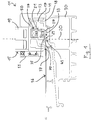
- Fig. 1 shows the lower portion of a lift-and-slide door 11, which has a horizontally displaceable wing 15.
- the wing 15 comprises a casement profile 17 and a glass element 19 held by the latter, which is embodied here as a multi-pane glass element.
- a wing plane 20 is defined.
- a plurality of carriages 21 For displacement of the wing 15, an arrangement of a plurality of carriages 21 is provided, of which in Fig. 1 only one is recognizable.
- the carriage 21 roll by means of rotatably mounted rollers 27 on a arranged below the wing 15 running rail 29 from.
- the running rail 29 is fixed in the illustrated embodiment to a threshold 30, but could also be integrally formed therewith.
- the running rail 29 has an upwardly projecting guide rib 33, whose upper portion forms a raceway 35, along which the wing 15 is displaceable by means of the carriages 21.
- the wing 15 between the in Fig. 1 shown raised traversing position and a lowered fixing position can be adjusted.
- the wing 15 sits on the ground 36 and is immovable.
- one, preferably level, support surface 38 is formed, which comes when lowering the wing 15 in contact with a bottom plane 39, which is defined by the bottom sill 30.
- the carriages 21 are accommodated in a lower-side receptacle 37 of the casement profile 17 in such a way that the rollers 27 protrude downward both with the raised wing 15 and with the wing 15 lowered relative to the support surface 38.
- a seating of the wing 15 on the threshold 30 in spite of the downwardly projecting rollers 27 is therefore possible because the running rail 29 is disposed in a recess 45 of the bottom sill 30, that is lowered relative to the ground plane 39.
- the recess 45 forms a sort of receptacle for the protruding part of the rollers 27.
- the guide rib 33 of the slide rail 29 is within the recess 45 from above, but does not protrude beyond the bottom plane 39 addition.
- On both sides of the track 35 surface regions 70 of the track 29 are formed, which are arranged below the bottom plane 39.
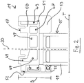
- Fig. 2 shows the upper portion of the lift and slide door 11.
- the sash profile 17 is designed in this area similar to the lower area, but with no recordings for carriage are provided.
- the sash frame profile 17 comprises a carrier 50, which is designed as a hollow profile with three separate, juxtaposed chambers 47. Depending on the application requirement, more than three or less than three chambers may be provided.
- the measured parallel to the wing plane 20 width B of the sash profile 17 is in the illustrated example about 50 mm.
- the ratio of the measured parallel to the wing plane 20 width B of the sash profile 17 to the perpendicular to the wing plane 20 measured depth T of the sash profile 17 is about 0.57.
- two reinforcing receptacles 49 are formed, in which, if necessary, flat steel inserts (not shown) can be used.
- the in Fig. 1 and 2 shown carrier 50 has an inner side 51 and an opposite outer side 52.
- the inner side 51 faces an interior of a building, while the outer side 52 is disposed on an outer wall of the building.
- the carrier 50 is preferably made entirely of a glass fiber reinforced plastic (GRP).
- Detectable threshold 30 is preferably made of a glass fiber reinforced plastic.
- a wooden panel 53 is attached, while on the outer side 52 of the carrier 50, an aluminum panel 55 is attached.
- an aluminum panel 55 is attached.
- Fig. 3 shows a side region of the lift-and-slide door 11, which is associated with the closing edge 60 of the wing 15. It can be seen a fitting gear 63, which is inserted into the casement profile 17. The fitting 63 is actuated by a handle 65. Due to the narrow design of the casement profile 17, the fitting gear 63 is not completely taken up in the casement profile 17, but projects in the direction of a frame 67. It is therefore a recess 69 formed in the frame 67, in which the protruding part of the fitting gear 63 moves when closing the wing 15.
- the lift-and-slide door 11 according to the invention is optically particularly attractive due to the narrow design of the casement profile 17 and the accordingly large-area glazing.
- the stable design of the sash profile 17 using glass fiber reinforced plastic allows this Provision of particularly large and heavy wings 15 while maintaining the usual thermal insulation requirements.
Landscapes
- Engineering & Computer Science (AREA)
- Civil Engineering (AREA)
- Structural Engineering (AREA)
- Mechanical Engineering (AREA)
- Wing Frames And Configurations (AREA)
- Specific Sealing Or Ventilating Devices For Doors And Windows (AREA)
- Support Devices For Sliding Doors (AREA)
Applications Claiming Priority (1)
| Application Number | Priority Date | Filing Date | Title |
|---|---|---|---|
| DE102018103776.7A DE102018103776A1 (de) | 2018-02-20 | 2018-02-20 | Hebeschiebe-Element |
Publications (2)
| Publication Number | Publication Date |
|---|---|
| EP3527767A1 true EP3527767A1 (fr) | 2019-08-21 |
| EP3527767B1 EP3527767B1 (fr) | 2023-06-21 |
Family
ID=65013590
Family Applications (1)
| Application Number | Title | Priority Date | Filing Date |
|---|---|---|---|
| EP19151202.9A Active EP3527767B1 (fr) | 2018-02-20 | 2019-01-10 | Élément coulissant basculant |
Country Status (2)
| Country | Link |
|---|---|
| EP (1) | EP3527767B1 (fr) |
| DE (1) | DE102018103776A1 (fr) |
Cited By (1)
| Publication number | Priority date | Publication date | Assignee | Title |
|---|---|---|---|---|
| IT202300016755A1 (it) * | 2023-08-04 | 2025-02-04 | Antonio Guidara | Sistema di guida per serramenti scorrevoli, quali cancelli e simili |
Families Citing this family (1)
| Publication number | Priority date | Publication date | Assignee | Title |
|---|---|---|---|---|
| DE102022204890A1 (de) * | 2022-05-17 | 2023-11-23 | Roto Frank Fenster- und Türtechnologie GmbH | Barrierefreie Schiebetür mit einem querabstellbaren Flügel |
Citations (2)
| Publication number | Priority date | Publication date | Assignee | Title |
|---|---|---|---|---|
| DE102015007386A1 (de) * | 2015-06-10 | 2016-12-15 | Sfs Intec Holding Ag | Rahmen für ein Fenster- oder Schiebetürelement |
| DE202017001325U1 (de) * | 2017-03-13 | 2017-03-31 | Siegenia-Aubi Kg | Bodenschwellensystem für einen verschiebbaren Flügel als Schiebeflügel oder verschiebaren Hebe-Schiebeflügel eines Fensters oder einer Tür |
Family Cites Families (7)
| Publication number | Priority date | Publication date | Assignee | Title |
|---|---|---|---|---|
| DE2143698A1 (de) * | 1971-09-01 | 1973-07-26 | Dynamit Nobel Ag | Stranggepresste profile, vorzugsweise aus einem thermoplastischen kunststoff, fuer blendrahmen und fluegelrahmen von schiebefenstern, schiebetueren o.dgl |
| US7520093B2 (en) * | 2004-01-13 | 2009-04-21 | Beat Guhl | Frame construction of a sliding door |
| AT9285U1 (de) * | 2007-03-13 | 2007-07-15 | Franz Matauschek | Rahmenlose tür oder fenster, insbesondere schiebetür oder -fenster |
| DE202009011741U1 (de) * | 2009-08-31 | 2011-01-13 | Rehau Ag + Co. | Laufwagengehäuse für eine Hebe-Schiebe-Tür oder ein Hebe-Schiebe-Fenster sowie Hebe-Schiebe-Tür oder Hebe-Schiebe-Fenster, die/das ein derartiges Laufwagengehäuse umfasst |
| CN205224960U (zh) * | 2015-10-13 | 2016-05-11 | 运城市太运建材有限公司 | 一种新型玻璃钢单扇推拉窗 |
| DE102015122312B4 (de) * | 2015-12-18 | 2024-07-11 | Claudia Rager-Frey | Hebeschiebetür |
| DE102016103340A1 (de) * | 2016-02-25 | 2017-08-31 | Maco Technologie Gmbh | Beschlaganordnung für eine schiebetüre |
-
2018
- 2018-02-20 DE DE102018103776.7A patent/DE102018103776A1/de not_active Withdrawn
-
2019
- 2019-01-10 EP EP19151202.9A patent/EP3527767B1/fr active Active
Patent Citations (2)
| Publication number | Priority date | Publication date | Assignee | Title |
|---|---|---|---|---|
| DE102015007386A1 (de) * | 2015-06-10 | 2016-12-15 | Sfs Intec Holding Ag | Rahmen für ein Fenster- oder Schiebetürelement |
| DE202017001325U1 (de) * | 2017-03-13 | 2017-03-31 | Siegenia-Aubi Kg | Bodenschwellensystem für einen verschiebbaren Flügel als Schiebeflügel oder verschiebaren Hebe-Schiebeflügel eines Fensters oder einer Tür |
Cited By (1)
| Publication number | Priority date | Publication date | Assignee | Title |
|---|---|---|---|---|
| IT202300016755A1 (it) * | 2023-08-04 | 2025-02-04 | Antonio Guidara | Sistema di guida per serramenti scorrevoli, quali cancelli e simili |
Also Published As
| Publication number | Publication date |
|---|---|
| EP3527767B1 (fr) | 2023-06-21 |
| DE102018103776A1 (de) | 2019-08-22 |
Similar Documents
| Publication | Publication Date | Title |
|---|---|---|
| EP2685039B1 (fr) | Dispositif de guidage, chariot et rail de guidage | |
| EP3596295B1 (fr) | Système seuil pour battant mobile utilisé comme battant coulissant ou battant levant-coulissant mobile d'une fenêtre ou d'une porte | |
| EP3488065A1 (fr) | Système seuil pour un battant mobile faisant office de battant coulissant ou un battant levant-coulissant mobile d'une fenêtre ou d'une porte | |
| EP3527767B1 (fr) | Élément coulissant basculant | |
| EP3527768A1 (fr) | Agencement pour un élément pivotant-coulissant | |
| DE4305283C1 (de) | Fenster oder Tür mit einem Rolladenkasten | |
| DE102018007189A1 (de) | Anordnung für ein Hebeschiebe-Element | |
| WO2011067210A2 (fr) | Paroi coulissante comportant au moins deux vantaux | |
| DE202018006958U1 (de) | Anordnung für ein Hebeschiebe-Element | |
| DE2342607A1 (de) | Mit mehrfachverglasung versehenes fenster oder versehene tuere mit aus kunststoff bestehendem fluegelrahmen | |
| DE102008039415B4 (de) | Schiebebeschlag | |
| DE202007019187U1 (de) | Sektionaltor | |
| DE19609624C2 (de) | Gebäudefenster und/oder Gebäudefenstertür | |
| DE10231841A1 (de) | Schiebetür | |
| AT513293B1 (de) | Tür oder Fenster, insbesondere Schiebetür oder Schiebefenster | |
| EP1371598A1 (fr) | Porte palière | |
| DE19622725C2 (de) | Gebäudefenster und/oder Gebäudefenstertür | |
| DE2626613A1 (de) | Hebeschiebefluegel, insbesondere fuer fenster | |
| DE20313145U1 (de) | Hebe-Schiebe-Tür oder -Fenster sowie Treibstangenbeschlag für Hebe-Schiebe-Türen oder -Fenster | |
| WO2024260867A1 (fr) | Seuil | |
| DE9412866U1 (de) | Klotz für Fenster oder Türen | |
| AT505999A1 (de) | Hohlkammerprofil | |
| DE202022000276U1 (de) | Leicht montierbare einteilige Führungsvorrichtung zur zuverlässigen Führung von hängenden Schiebetüren und eine Schiebetürvorrichtung zur verkantungsfrei bedienbaren Führung einer Schiebetür | |
| DE814219C (de) | Rahmen aus Hohlprofilen, insbesondere Fensterrahmen | |
| DE8437717U1 (de) | Beschlag für Schiebetüren und Schiebefenster |
Legal Events
| Date | Code | Title | Description |
|---|---|---|---|
| PUAI | Public reference made under article 153(3) epc to a published international application that has entered the european phase |
Free format text: ORIGINAL CODE: 0009012 |
|
| STAA | Information on the status of an ep patent application or granted ep patent |
Free format text: STATUS: THE APPLICATION HAS BEEN PUBLISHED |
|
| AK | Designated contracting states |
Kind code of ref document: A1 Designated state(s): AL AT BE BG CH CY CZ DE DK EE ES FI FR GB GR HR HU IE IS IT LI LT LU LV MC MK MT NL NO PL PT RO RS SE SI SK SM TR |
|
| AX | Request for extension of the european patent |
Extension state: BA ME |
|
| STAA | Information on the status of an ep patent application or granted ep patent |
Free format text: STATUS: REQUEST FOR EXAMINATION WAS MADE |
|
| 17P | Request for examination filed |
Effective date: 20191023 |
|
| RBV | Designated contracting states (corrected) |
Designated state(s): AL AT BE BG CH CY CZ DE DK EE ES FI FR GB GR HR HU IE IS IT LI LT LU LV MC MK MT NL NO PL PT RO RS SE SI SK SM TR |
|
| STAA | Information on the status of an ep patent application or granted ep patent |
Free format text: STATUS: EXAMINATION IS IN PROGRESS |
|
| 17Q | First examination report despatched |
Effective date: 20210429 |
|
| GRAP | Despatch of communication of intention to grant a patent |
Free format text: ORIGINAL CODE: EPIDOSNIGR1 |
|
| STAA | Information on the status of an ep patent application or granted ep patent |
Free format text: STATUS: GRANT OF PATENT IS INTENDED |
|
| INTG | Intention to grant announced |
Effective date: 20230310 |
|
| GRAS | Grant fee paid |
Free format text: ORIGINAL CODE: EPIDOSNIGR3 |
|
| GRAA | (expected) grant |
Free format text: ORIGINAL CODE: 0009210 |
|
| STAA | Information on the status of an ep patent application or granted ep patent |
Free format text: STATUS: THE PATENT HAS BEEN GRANTED |
|
| AK | Designated contracting states |
Kind code of ref document: B1 Designated state(s): AL AT BE BG CH CY CZ DE DK EE ES FI FR GB GR HR HU IE IS IT LI LT LU LV MC MK MT NL NO PL PT RO RS SE SI SK SM TR |
|
| REG | Reference to a national code |
Ref country code: CH Ref legal event code: EP |
|
| REG | Reference to a national code |
Ref country code: DE Ref legal event code: R096 Ref document number: 502019008223 Country of ref document: DE |
|
| REG | Reference to a national code |
Ref country code: AT Ref legal event code: REF Ref document number: 1581014 Country of ref document: AT Kind code of ref document: T Effective date: 20230715 |
|
| REG | Reference to a national code |
Ref country code: IE Ref legal event code: FG4D Free format text: LANGUAGE OF EP DOCUMENT: GERMAN |
|
| REG | Reference to a national code |
Ref country code: LT Ref legal event code: MG9D |
|
| REG | Reference to a national code |
Ref country code: NL Ref legal event code: MP Effective date: 20230621 |
|
| PG25 | Lapsed in a contracting state [announced via postgrant information from national office to epo] |
Ref country code: SE Free format text: LAPSE BECAUSE OF FAILURE TO SUBMIT A TRANSLATION OF THE DESCRIPTION OR TO PAY THE FEE WITHIN THE PRESCRIBED TIME-LIMIT Effective date: 20230621 Ref country code: NO Free format text: LAPSE BECAUSE OF FAILURE TO SUBMIT A TRANSLATION OF THE DESCRIPTION OR TO PAY THE FEE WITHIN THE PRESCRIBED TIME-LIMIT Effective date: 20230921 |
|
| PG25 | Lapsed in a contracting state [announced via postgrant information from national office to epo] |
Ref country code: NL Free format text: LAPSE BECAUSE OF FAILURE TO SUBMIT A TRANSLATION OF THE DESCRIPTION OR TO PAY THE FEE WITHIN THE PRESCRIBED TIME-LIMIT Effective date: 20230621 Ref country code: LV Free format text: LAPSE BECAUSE OF FAILURE TO SUBMIT A TRANSLATION OF THE DESCRIPTION OR TO PAY THE FEE WITHIN THE PRESCRIBED TIME-LIMIT Effective date: 20230621 Ref country code: LT Free format text: LAPSE BECAUSE OF FAILURE TO SUBMIT A TRANSLATION OF THE DESCRIPTION OR TO PAY THE FEE WITHIN THE PRESCRIBED TIME-LIMIT Effective date: 20230621 Ref country code: HR Free format text: LAPSE BECAUSE OF FAILURE TO SUBMIT A TRANSLATION OF THE DESCRIPTION OR TO PAY THE FEE WITHIN THE PRESCRIBED TIME-LIMIT Effective date: 20230621 Ref country code: GR Free format text: LAPSE BECAUSE OF FAILURE TO SUBMIT A TRANSLATION OF THE DESCRIPTION OR TO PAY THE FEE WITHIN THE PRESCRIBED TIME-LIMIT Effective date: 20230922 Ref country code: RS Free format text: LAPSE BECAUSE OF FAILURE TO SUBMIT A TRANSLATION OF THE DESCRIPTION OR TO PAY THE FEE WITHIN THE PRESCRIBED TIME-LIMIT Effective date: 20230621 |
|
| PG25 | Lapsed in a contracting state [announced via postgrant information from national office to epo] |
Ref country code: FI Free format text: LAPSE BECAUSE OF FAILURE TO SUBMIT A TRANSLATION OF THE DESCRIPTION OR TO PAY THE FEE WITHIN THE PRESCRIBED TIME-LIMIT Effective date: 20230621 |
|
| PG25 | Lapsed in a contracting state [announced via postgrant information from national office to epo] |
Ref country code: SK Free format text: LAPSE BECAUSE OF FAILURE TO SUBMIT A TRANSLATION OF THE DESCRIPTION OR TO PAY THE FEE WITHIN THE PRESCRIBED TIME-LIMIT Effective date: 20230621 |
|
| PG25 | Lapsed in a contracting state [announced via postgrant information from national office to epo] |
Ref country code: ES Free format text: LAPSE BECAUSE OF FAILURE TO SUBMIT A TRANSLATION OF THE DESCRIPTION OR TO PAY THE FEE WITHIN THE PRESCRIBED TIME-LIMIT Effective date: 20230621 |
|
| PG25 | Lapsed in a contracting state [announced via postgrant information from national office to epo] |
Ref country code: IS Free format text: LAPSE BECAUSE OF FAILURE TO SUBMIT A TRANSLATION OF THE DESCRIPTION OR TO PAY THE FEE WITHIN THE PRESCRIBED TIME-LIMIT Effective date: 20231021 |
|
| PG25 | Lapsed in a contracting state [announced via postgrant information from national office to epo] |
Ref country code: SM Free format text: LAPSE BECAUSE OF FAILURE TO SUBMIT A TRANSLATION OF THE DESCRIPTION OR TO PAY THE FEE WITHIN THE PRESCRIBED TIME-LIMIT Effective date: 20230621 Ref country code: SK Free format text: LAPSE BECAUSE OF FAILURE TO SUBMIT A TRANSLATION OF THE DESCRIPTION OR TO PAY THE FEE WITHIN THE PRESCRIBED TIME-LIMIT Effective date: 20230621 Ref country code: RO Free format text: LAPSE BECAUSE OF FAILURE TO SUBMIT A TRANSLATION OF THE DESCRIPTION OR TO PAY THE FEE WITHIN THE PRESCRIBED TIME-LIMIT Effective date: 20230621 Ref country code: PT Free format text: LAPSE BECAUSE OF FAILURE TO SUBMIT A TRANSLATION OF THE DESCRIPTION OR TO PAY THE FEE WITHIN THE PRESCRIBED TIME-LIMIT Effective date: 20231023 Ref country code: IS Free format text: LAPSE BECAUSE OF FAILURE TO SUBMIT A TRANSLATION OF THE DESCRIPTION OR TO PAY THE FEE WITHIN THE PRESCRIBED TIME-LIMIT Effective date: 20231021 Ref country code: ES Free format text: LAPSE BECAUSE OF FAILURE TO SUBMIT A TRANSLATION OF THE DESCRIPTION OR TO PAY THE FEE WITHIN THE PRESCRIBED TIME-LIMIT Effective date: 20230621 Ref country code: EE Free format text: LAPSE BECAUSE OF FAILURE TO SUBMIT A TRANSLATION OF THE DESCRIPTION OR TO PAY THE FEE WITHIN THE PRESCRIBED TIME-LIMIT Effective date: 20230621 Ref country code: CZ Free format text: LAPSE BECAUSE OF FAILURE TO SUBMIT A TRANSLATION OF THE DESCRIPTION OR TO PAY THE FEE WITHIN THE PRESCRIBED TIME-LIMIT Effective date: 20230621 |
|
| PG25 | Lapsed in a contracting state [announced via postgrant information from national office to epo] |
Ref country code: PL Free format text: LAPSE BECAUSE OF FAILURE TO SUBMIT A TRANSLATION OF THE DESCRIPTION OR TO PAY THE FEE WITHIN THE PRESCRIBED TIME-LIMIT Effective date: 20230621 |
|
| REG | Reference to a national code |
Ref country code: DE Ref legal event code: R097 Ref document number: 502019008223 Country of ref document: DE |
|
| PLBE | No opposition filed within time limit |
Free format text: ORIGINAL CODE: 0009261 |
|
| STAA | Information on the status of an ep patent application or granted ep patent |
Free format text: STATUS: NO OPPOSITION FILED WITHIN TIME LIMIT |
|
| PG25 | Lapsed in a contracting state [announced via postgrant information from national office to epo] |
Ref country code: DK Free format text: LAPSE BECAUSE OF FAILURE TO SUBMIT A TRANSLATION OF THE DESCRIPTION OR TO PAY THE FEE WITHIN THE PRESCRIBED TIME-LIMIT Effective date: 20230621 |
|
| PG25 | Lapsed in a contracting state [announced via postgrant information from national office to epo] |
Ref country code: SI Free format text: LAPSE BECAUSE OF FAILURE TO SUBMIT A TRANSLATION OF THE DESCRIPTION OR TO PAY THE FEE WITHIN THE PRESCRIBED TIME-LIMIT Effective date: 20230621 |
|
| 26N | No opposition filed |
Effective date: 20240322 |
|
| PG25 | Lapsed in a contracting state [announced via postgrant information from national office to epo] |
Ref country code: SI Free format text: LAPSE BECAUSE OF FAILURE TO SUBMIT A TRANSLATION OF THE DESCRIPTION OR TO PAY THE FEE WITHIN THE PRESCRIBED TIME-LIMIT Effective date: 20230621 |
|
| PG25 | Lapsed in a contracting state [announced via postgrant information from national office to epo] |
Ref country code: MC Free format text: LAPSE BECAUSE OF FAILURE TO SUBMIT A TRANSLATION OF THE DESCRIPTION OR TO PAY THE FEE WITHIN THE PRESCRIBED TIME-LIMIT Effective date: 20230621 |
|
| PG25 | Lapsed in a contracting state [announced via postgrant information from national office to epo] |
Ref country code: MC Free format text: LAPSE BECAUSE OF FAILURE TO SUBMIT A TRANSLATION OF THE DESCRIPTION OR TO PAY THE FEE WITHIN THE PRESCRIBED TIME-LIMIT Effective date: 20230621 |
|
| REG | Reference to a national code |
Ref country code: CH Ref legal event code: PL |
|
| PG25 | Lapsed in a contracting state [announced via postgrant information from national office to epo] |
Ref country code: LU Free format text: LAPSE BECAUSE OF NON-PAYMENT OF DUE FEES Effective date: 20240110 |
|
| GBPC | Gb: european patent ceased through non-payment of renewal fee |
Effective date: 20240110 |
|
| PG25 | Lapsed in a contracting state [announced via postgrant information from national office to epo] |
Ref country code: LU Free format text: LAPSE BECAUSE OF NON-PAYMENT OF DUE FEES Effective date: 20240110 |
|
| PG25 | Lapsed in a contracting state [announced via postgrant information from national office to epo] |
Ref country code: GB Free format text: LAPSE BECAUSE OF NON-PAYMENT OF DUE FEES Effective date: 20240110 |
|
| PG25 | Lapsed in a contracting state [announced via postgrant information from national office to epo] |
Ref country code: BE Free format text: LAPSE BECAUSE OF NON-PAYMENT OF DUE FEES Effective date: 20240131 |
|
| PG25 | Lapsed in a contracting state [announced via postgrant information from national office to epo] |
Ref country code: FR Free format text: LAPSE BECAUSE OF NON-PAYMENT OF DUE FEES Effective date: 20240131 |
|
| PG25 | Lapsed in a contracting state [announced via postgrant information from national office to epo] |
Ref country code: CH Free format text: LAPSE BECAUSE OF NON-PAYMENT OF DUE FEES Effective date: 20240131 |
|
| PG25 | Lapsed in a contracting state [announced via postgrant information from national office to epo] |
Ref country code: GB Free format text: LAPSE BECAUSE OF NON-PAYMENT OF DUE FEES Effective date: 20240110 Ref country code: FR Free format text: LAPSE BECAUSE OF NON-PAYMENT OF DUE FEES Effective date: 20240131 Ref country code: CH Free format text: LAPSE BECAUSE OF NON-PAYMENT OF DUE FEES Effective date: 20240131 Ref country code: BE Free format text: LAPSE BECAUSE OF NON-PAYMENT OF DUE FEES Effective date: 20240131 |
|
| REG | Reference to a national code |
Ref country code: BE Ref legal event code: MM Effective date: 20240131 |
|
| PG25 | Lapsed in a contracting state [announced via postgrant information from national office to epo] |
Ref country code: BG Free format text: LAPSE BECAUSE OF FAILURE TO SUBMIT A TRANSLATION OF THE DESCRIPTION OR TO PAY THE FEE WITHIN THE PRESCRIBED TIME-LIMIT Effective date: 20230621 |
|
| PG25 | Lapsed in a contracting state [announced via postgrant information from national office to epo] |
Ref country code: BG Free format text: LAPSE BECAUSE OF FAILURE TO SUBMIT A TRANSLATION OF THE DESCRIPTION OR TO PAY THE FEE WITHIN THE PRESCRIBED TIME-LIMIT Effective date: 20230621 |
|
| PG25 | Lapsed in a contracting state [announced via postgrant information from national office to epo] |
Ref country code: IE Free format text: LAPSE BECAUSE OF NON-PAYMENT OF DUE FEES Effective date: 20240110 |
|
| PG25 | Lapsed in a contracting state [announced via postgrant information from national office to epo] |
Ref country code: IE Free format text: LAPSE BECAUSE OF NON-PAYMENT OF DUE FEES Effective date: 20240110 |
|
| PG25 | Lapsed in a contracting state [announced via postgrant information from national office to epo] |
Ref country code: CY Free format text: LAPSE BECAUSE OF FAILURE TO SUBMIT A TRANSLATION OF THE DESCRIPTION OR TO PAY THE FEE WITHIN THE PRESCRIBED TIME-LIMIT; INVALID AB INITIO Effective date: 20190110 |
|
| PG25 | Lapsed in a contracting state [announced via postgrant information from national office to epo] |
Ref country code: HU Free format text: LAPSE BECAUSE OF FAILURE TO SUBMIT A TRANSLATION OF THE DESCRIPTION OR TO PAY THE FEE WITHIN THE PRESCRIBED TIME-LIMIT; INVALID AB INITIO Effective date: 20190110 |
|
| PG25 | Lapsed in a contracting state [announced via postgrant information from national office to epo] |
Ref country code: TR Free format text: LAPSE BECAUSE OF FAILURE TO SUBMIT A TRANSLATION OF THE DESCRIPTION OR TO PAY THE FEE WITHIN THE PRESCRIBED TIME-LIMIT Effective date: 20230621 |
|
| PGFP | Annual fee paid to national office [announced via postgrant information from national office to epo] |
Ref country code: DE Payment date: 20260121 Year of fee payment: 8 |
|
| PGFP | Annual fee paid to national office [announced via postgrant information from national office to epo] |
Ref country code: AT Payment date: 20260122 Year of fee payment: 8 |
|
| PGFP | Annual fee paid to national office [announced via postgrant information from national office to epo] |
Ref country code: IT Payment date: 20260126 Year of fee payment: 8 |