EP0472906A2 - Procédé et dispositif pour le chauffage de couches extérieures pour la fabrication d'éléments-sandwich à partir de matières plastiques à plusieurs composants - Google Patents
Procédé et dispositif pour le chauffage de couches extérieures pour la fabrication d'éléments-sandwich à partir de matières plastiques à plusieurs composants Download PDFInfo
- Publication number
- EP0472906A2 EP0472906A2 EP91112374A EP91112374A EP0472906A2 EP 0472906 A2 EP0472906 A2 EP 0472906A2 EP 91112374 A EP91112374 A EP 91112374A EP 91112374 A EP91112374 A EP 91112374A EP 0472906 A2 EP0472906 A2 EP 0472906A2
- Authority
- EP
- European Patent Office
- Prior art keywords
- air
- cover layer
- heating
- circuit
- heated
- Prior art date
- Legal status (The legal status is an assumption and is not a legal conclusion. Google has not performed a legal analysis and makes no representation as to the accuracy of the status listed.)
- Granted
Links
Images


Classifications
-
- B—PERFORMING OPERATIONS; TRANSPORTING
- B32—LAYERED PRODUCTS
- B32B—LAYERED PRODUCTS, i.e. PRODUCTS BUILT-UP OF STRATA OF FLAT OR NON-FLAT, e.g. CELLULAR OR HONEYCOMB, FORM
- B32B37/00—Methods or apparatus for laminating, e.g. by curing or by ultrasonic bonding
- B32B37/10—Methods or apparatus for laminating, e.g. by curing or by ultrasonic bonding characterised by the pressing technique, e.g. using action of vacuum or fluid pressure
- B32B37/1027—Pressing using at least one press band
-
- B—PERFORMING OPERATIONS; TRANSPORTING
- B29—WORKING OF PLASTICS; WORKING OF SUBSTANCES IN A PLASTIC STATE IN GENERAL
- B29C—SHAPING OR JOINING OF PLASTICS; SHAPING OF MATERIAL IN A PLASTIC STATE, NOT OTHERWISE PROVIDED FOR; AFTER-TREATMENT OF THE SHAPED PRODUCTS, e.g. REPAIRING
- B29C44/00—Shaping by internal pressure generated in the material, e.g. swelling or foaming ; Producing porous or cellular expanded plastics articles
- B29C44/20—Shaping by internal pressure generated in the material, e.g. swelling or foaming ; Producing porous or cellular expanded plastics articles for articles of indefinite length
- B29C44/32—Incorporating or moulding on preformed parts, e.g. linings, inserts or reinforcements
- B29C44/321—Incorporating or moulding on preformed parts, e.g. linings, inserts or reinforcements the preformed part being a lining, e.g. a film or a support lining
-
- B—PERFORMING OPERATIONS; TRANSPORTING
- B32—LAYERED PRODUCTS
- B32B—LAYERED PRODUCTS, i.e. PRODUCTS BUILT-UP OF STRATA OF FLAT OR NON-FLAT, e.g. CELLULAR OR HONEYCOMB, FORM
- B32B38/00—Ancillary operations in connection with laminating processes
- B32B38/0036—Heat treatment
-
- F—MECHANICAL ENGINEERING; LIGHTING; HEATING; WEAPONS; BLASTING
- F27—FURNACES; KILNS; OVENS; RETORTS
- F27B—FURNACES, KILNS, OVENS OR RETORTS IN GENERAL; OPEN SINTERING OR LIKE APPARATUS
- F27B9/00—Furnaces through which the charge is moved mechanically, e.g. of tunnel type; Similar furnaces in which the charge moves by gravity
- F27B9/06—Furnaces through which the charge is moved mechanically, e.g. of tunnel type; Similar furnaces in which the charge moves by gravity heated without contact between combustion gases and charge; electrically heated
- F27B9/10—Furnaces through which the charge is moved mechanically, e.g. of tunnel type; Similar furnaces in which the charge moves by gravity heated without contact between combustion gases and charge; electrically heated heated by hot air or gas
-
- F—MECHANICAL ENGINEERING; LIGHTING; HEATING; WEAPONS; BLASTING
- F27—FURNACES; KILNS; OVENS; RETORTS
- F27B—FURNACES, KILNS, OVENS OR RETORTS IN GENERAL; OPEN SINTERING OR LIKE APPARATUS
- F27B9/00—Furnaces through which the charge is moved mechanically, e.g. of tunnel type; Similar furnaces in which the charge moves by gravity
- F27B9/30—Details, accessories or equipment specially adapted for furnaces of these types
- F27B9/3005—Details, accessories or equipment specially adapted for furnaces of these types arrangements for circulating gases
- F27B9/3011—Details, accessories or equipment specially adapted for furnaces of these types arrangements for circulating gases arrangements for circulating gases transversally
-
- F—MECHANICAL ENGINEERING; LIGHTING; HEATING; WEAPONS; BLASTING
- F27—FURNACES; KILNS; OVENS; RETORTS
- F27B—FURNACES, KILNS, OVENS OR RETORTS IN GENERAL; OPEN SINTERING OR LIKE APPARATUS
- F27B9/00—Furnaces through which the charge is moved mechanically, e.g. of tunnel type; Similar furnaces in which the charge moves by gravity
- F27B9/30—Details, accessories or equipment specially adapted for furnaces of these types
- F27B9/40—Arrangements of controlling or monitoring devices
-
- F—MECHANICAL ENGINEERING; LIGHTING; HEATING; WEAPONS; BLASTING
- F27—FURNACES; KILNS; OVENS; RETORTS
- F27B—FURNACES, KILNS, OVENS OR RETORTS IN GENERAL; OPEN SINTERING OR LIKE APPARATUS
- F27B9/00—Furnaces through which the charge is moved mechanically, e.g. of tunnel type; Similar furnaces in which the charge moves by gravity
- F27B9/30—Details, accessories or equipment specially adapted for furnaces of these types
- F27B9/3005—Details, accessories or equipment specially adapted for furnaces of these types arrangements for circulating gases
- F27B2009/3027—Use of registers, partitions
-
- F—MECHANICAL ENGINEERING; LIGHTING; HEATING; WEAPONS; BLASTING
- F27—FURNACES; KILNS; OVENS; RETORTS
- F27B—FURNACES, KILNS, OVENS OR RETORTS IN GENERAL; OPEN SINTERING OR LIKE APPARATUS
- F27B9/00—Furnaces through which the charge is moved mechanically, e.g. of tunnel type; Similar furnaces in which the charge moves by gravity
- F27B9/28—Furnaces through which the charge is moved mechanically, e.g. of tunnel type; Similar furnaces in which the charge moves by gravity for treating continuous lengths of work
-
- F—MECHANICAL ENGINEERING; LIGHTING; HEATING; WEAPONS; BLASTING
- F27—FURNACES; KILNS; OVENS; RETORTS
- F27D—DETAILS OR ACCESSORIES OF FURNACES, KILNS, OVENS OR RETORTS, IN SO FAR AS THEY ARE OF KINDS OCCURRING IN MORE THAN ONE KIND OF FURNACE
- F27D19/00—Arrangements of controlling devices
- F27D2019/0003—Monitoring the temperature or a characteristic of the charge and using it as a controlling value
-
- F—MECHANICAL ENGINEERING; LIGHTING; HEATING; WEAPONS; BLASTING
- F27—FURNACES; KILNS; OVENS; RETORTS
- F27D—DETAILS OR ACCESSORIES OF FURNACES, KILNS, OVENS OR RETORTS, IN SO FAR AS THEY ARE OF KINDS OCCURRING IN MORE THAN ONE KIND OF FURNACE
- F27D19/00—Arrangements of controlling devices
- F27D2019/0028—Regulation
- F27D2019/0034—Regulation through control of a heating quantity such as fuel, oxidant or intensity of current
- F27D2019/0037—Quantity of electric current
Definitions
- the invention relates to a method and a device according to the preamble of claims 1 and 2 respectively.
- the device is part of a so-called double belt system, in which sandwich elements are preferably continuously laminated with metallic cover layers.
- the metallic cover layers are often profiled before entering the device according to the invention, so that the corresponding sandwich element then has a correspondingly profiled surface.
- An essential element of such a plant for the production of sandwich elements is the so-called double belt, into which the cover layers provided for the upper and lower lamination enter at a distance from one another, the multi-component plastic which foams there being introduced between the cover layers. After the multi-component plastic has reacted, an endless strand emerges from the double band, which is then only cut to length. The cut-to-length material elements are then stacked.
- the cover layers must be preheated to ensure a good connection with the reacting and foaming multi-component plastics. It is important that the cover layers have a uniform, predetermined temperature. As long as the cover layers are continuously conveyed, i.e. the double belt system works without interruption, the heating of the two outer layers does not pose any special requirements.
- the invention is therefore based on the object of providing a method and a device of the type mentioned at the outset in order to ensure that the outer layers are heated to a constant temperature within very narrow, defined limits even when the conveying of the outer layers is interrupted, i.e. Even when starting up again, the top layers should be run into the double belt at the desired temperature after a short time.
- the device is advantageously constructed as defined in claim 3.
- the outer layers are heated with the aid of heated air, which is circulated in a furnace and heated in the process.
- the air is conducted at high speed through appropriate supply air and return air ducts, the outlet and inlet openings of which are located just above and below the surface layer to be heated. This ensures good heat transfer since the boundary layer is torn open.
- the inlet and outlet openings which lie transversely to the production direction, alternate with each other in the conveying direction of the cover layer, so that the heated air emerging from the openings of the supply air channels strikes the corresponding side of the cover layer, is deflected after a corresponding amount of heat has been released and through the openings of the return channels are returned to the circuit.
- the cover layer temperature sensor ensures that the air in the circuit is always kept at a temperature that ensures the desired cover layer temperature. If the conveyance of the cover layer is interrupted, the energy supply to the heating element is also switched off. The supply air ducts are switched off from the circuit, so that short-circuit conveyance from the return ducts arises directly to the compressor. At the same time, it is extracted into the outside air so that the excess heat is dissipated. When the appropriate amount of heat is removed is blown off to the environment is interrupted. The conveyance then takes place only in a short-circuited circuit, the temperature being kept at a set value by an internal temperature sensor which corresponds to the desired temperature of the top layer after restarting the system.
- the air flow is regulated by means of appropriate air flaps, external and internal flaps, which allow the air to be blown off to the environment when the vehicle is at a standstill and which switch off, i.e. cut off the supply air ducts if the top layer conveyance is interrupted.
- the temperature sensors are also controlled in such a way that the desired temperature of the outer layers is present and maintained when the system is restarted.
- the device shown schematically in the drawings - also referred to as an "oven" - basically consists of two such ovens 1 and 2, one of which is used to heat the upper cover layer 13 and the other to heat the lower cover layer 14, as is the case with Considering FIGS. 1 and 2 as a unit.
- both ovens are constructed the same, so that the same reference numerals have been used for the same parts.
- Each furnace is formed by a corresponding sheet metal housing in which the individual channels and the further elements and components are arranged.
- An exhaust air duct 3 leads out of each furnace and is normally separated from the interior of the furnace by an outer flap 17.
- the air circulated in the furnace is conveyed in a closed circuit. It is heated by a heating element 11, which is preferably an electrical resistance heating device with a short post-heating time and low mass of the heating grid.
- the air is conveyed using a compressor 10.
- the upper cover layer 13 runs through a boiler room 15 and the lower cover layer 14 through the same boiler room 16.
- These boiler rooms 15 and 16 are only supplied with heated air if the cover layer 13 or 14 is to be preheated accordingly. If this should not happen, in particular if there is an interruption in the conveying of the cover layer, the conveying of the air into these zones 15 and 16 is interrupted.
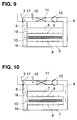
- FIGS. 5 and 8 which basically correspond to those according to FIGS. 4 and 7, a somewhat different flap construction is shown.
- the inner flaps are therefore designated 19a in this embodiment according to FIGS. 5 and 8.
- the flap position according to FIG. 5 corresponds to that according to FIG. 4 and the flap position according to FIG. 8 corresponds to that according to FIG. 7.
- the control of the temperature ie the control of the heating element 11 takes place during normal operation, ie with normal conveyance of the cover layer 13 by an external cover layer temperature sensor 18.
- the flaps are positioned as shown in FIGS. 7 and 8 or 9 and 10 .
- the air flow takes place as indicated by corresponding arrows in FIG. 6.
- the air emerging from the compressor 10 is heated in the heating element and, when the outer flap 17 is in the position shown in FIG. 1, is passed into the feed channel 6. Since the inner flaps 19 or 19a assume the position shown in FIGS. 7 and 8, the heated air enters the supply air ducts 5 and exits the slots 9 of these supply air ducts and strikes the corresponding side of the cover layer 13. After releasing the appropriate amount of heat the air flows through the slots 9 of the adjacent, alternately arranged return channels 7 to the discharge channel 8 and thus into the inlet area of the compressor 10. The circuit is closed and begins anew.
- the invention creates a preheating furnace for each top layer, in which the heated air is conveyed in a closed circuit.
- the heated residual air is blown off for a short time and at the same time there is a promotion in the short circuit to prevent further heating of the cover layer.
- the furnace and thus the cover layer are kept at a temperature which enables the desired cover layer temperature to be restarted without problems.
- the supply air and return air ducts which run alternately across the delivery direction on the top and bottom, ensure good heat transfer with a high energy density.
- the circular mode of operation ensures economical work in normal operation since no air is released into the environment. This only happens briefly when there is an interruption in order to prevent the covering layer from overheating.
Landscapes
- Engineering & Computer Science (AREA)
- Mechanical Engineering (AREA)
- General Engineering & Computer Science (AREA)
- Physics & Mathematics (AREA)
- Thermal Sciences (AREA)
- Chemical & Material Sciences (AREA)
- Combustion & Propulsion (AREA)
- Fluid Mechanics (AREA)
- Tunnel Furnaces (AREA)
- Lining Or Joining Of Plastics Or The Like (AREA)
- Heating, Cooling, Or Curing Plastics Or The Like In General (AREA)
Applications Claiming Priority (2)
| Application Number | Priority Date | Filing Date | Title |
|---|---|---|---|
| DE4024756 | 1990-08-03 | ||
| DE4024756A DE4024756A1 (de) | 1990-08-03 | 1990-08-03 | Verfahren und vorrichtung zum erwaermen von deckschichten zur herstellung von sandwichelementen aus mehrkomponenten-kuststoffen |
Publications (3)
| Publication Number | Publication Date |
|---|---|
| EP0472906A2 true EP0472906A2 (fr) | 1992-03-04 |
| EP0472906A3 EP0472906A3 (en) | 1992-03-18 |
| EP0472906B1 EP0472906B1 (fr) | 1995-04-12 |
Family
ID=6411633
Family Applications (1)
| Application Number | Title | Priority Date | Filing Date |
|---|---|---|---|
| EP91112374A Expired - Lifetime EP0472906B1 (fr) | 1990-08-03 | 1991-07-24 | Procédé et dispositif pour le chauffage de couches extérieures pour la fabrication d'éléments-sandwich à partir de matières plastiques à plusieurs composants |
Country Status (2)
| Country | Link |
|---|---|
| EP (1) | EP0472906B1 (fr) |
| DE (2) | DE4024756A1 (fr) |
Cited By (4)
| Publication number | Priority date | Publication date | Assignee | Title |
|---|---|---|---|---|
| EP0885706A3 (fr) * | 1997-06-20 | 1999-11-17 | Thermatech Timber Structures Ltd. | Procédé et dispositif de fabrication de panneaux |
| US6116895A (en) * | 1995-03-10 | 2000-09-12 | Mcneil-Ppc, Inc. | Dual mode convection oven |
| EP1146305A1 (fr) * | 2000-04-11 | 2001-10-17 | Siempelkamp Handling Systeme GmbH & Co. | Technique de préchauffage avec réduction de la puissance pendant les interruptions de fonctionnement |
| CN106393559A (zh) * | 2016-11-26 | 2017-02-15 | 滁州市荣康塑料制品有限公司 | 一种高光无痕注塑成型工艺 |
Families Citing this family (1)
| Publication number | Priority date | Publication date | Assignee | Title |
|---|---|---|---|---|
| DE19906751B4 (de) * | 1999-02-17 | 2016-06-02 | Maschinen Witte Gmbh & Co. Kg | Aufheizgerät |
Family Cites Families (4)
| Publication number | Priority date | Publication date | Assignee | Title |
|---|---|---|---|---|
| DK130368B (da) * | 1969-03-04 | 1975-02-10 | P H Lytzen | Fremgangsmåde til varmebehandling ved konvektion af flade enkeltemner eller fortløbende baner eller tråde, f.eks. af formstoffibre samt ovn til brug ved fremgangsmåden. |
| DE2536101A1 (de) * | 1975-08-13 | 1977-02-17 | Gerd Arweiler | Verfahren und vorrichtung zum erwaermen oder abkuehlen des endbereichs eines aufzumuffenden kunststoffrohres |
| IT1089549B (it) * | 1977-12-30 | 1985-06-18 | S I C A Spa | Dispositivo per il riscaldamento della estremita di tubi in materiale plastico |
| DE3138232C2 (de) * | 1981-09-25 | 1983-09-22 | Carl Prof. Dr.-Ing. Kramer | Tunnelofen |
-
1990
- 1990-08-03 DE DE4024756A patent/DE4024756A1/de not_active Withdrawn
-
1991
- 1991-07-24 EP EP91112374A patent/EP0472906B1/fr not_active Expired - Lifetime
- 1991-07-24 DE DE59105158T patent/DE59105158D1/de not_active Expired - Lifetime
Cited By (4)
| Publication number | Priority date | Publication date | Assignee | Title |
|---|---|---|---|---|
| US6116895A (en) * | 1995-03-10 | 2000-09-12 | Mcneil-Ppc, Inc. | Dual mode convection oven |
| EP0885706A3 (fr) * | 1997-06-20 | 1999-11-17 | Thermatech Timber Structures Ltd. | Procédé et dispositif de fabrication de panneaux |
| EP1146305A1 (fr) * | 2000-04-11 | 2001-10-17 | Siempelkamp Handling Systeme GmbH & Co. | Technique de préchauffage avec réduction de la puissance pendant les interruptions de fonctionnement |
| CN106393559A (zh) * | 2016-11-26 | 2017-02-15 | 滁州市荣康塑料制品有限公司 | 一种高光无痕注塑成型工艺 |
Also Published As
| Publication number | Publication date |
|---|---|
| EP0472906B1 (fr) | 1995-04-12 |
| DE59105158D1 (de) | 1995-05-18 |
| DE4024756A1 (de) | 1992-02-06 |
| EP0472906A3 (en) | 1992-03-18 |
Similar Documents
| Publication | Publication Date | Title |
|---|---|---|
| DE3850195T2 (de) | Aufschmelzofen. | |
| EP3542992B1 (fr) | Dispositif et procédé de changement des filaments de couleurs différentes et / ou de matériaux différents destinés à la fabrication de pièces imprimées tridimensionnelles ainsi qu'extruder avec un système de changement de filament | |
| DE69321618T2 (de) | Schweissverfahren zur herstellung von spiralformig gewickelten rohren und schweisskopf zur durchführung dieses verfahrens | |
| EP0251257A2 (fr) | Méthode et dispositif pour la soudure et la désoudure à reflux de plaquettes à circuits imprimés | |
| DE2950003C2 (de) | Verfahren zur Regelung der Foliendicke an einer Blasfolien-Extruderanlage | |
| DE2460270A1 (de) | Verfahren und vorrichtung zum herstellen von glasfaeden | |
| DE3328449A1 (de) | Vorrichtung zum strecken aus schaeren von thermoplastischen kettfaeden und verfahren zum betrieb dieser vorrichtung | |
| DE2710467C2 (de) | Vorrichtung zum Erhitzen einer Polymerfolienbahn vor dem Recken in Querrichtung | |
| EP0472906B1 (fr) | Procédé et dispositif pour le chauffage de couches extérieures pour la fabrication d'éléments-sandwich à partir de matières plastiques à plusieurs composants | |
| DE2907960C3 (de) | Verfahren und Vorrichtung zum kontinuierlichen Wärmebehandeln von vereinzeltem, langgestrecktem metallischen Gut | |
| WO2017186875A1 (fr) | Dispositif et procédé de conditionnement thermique de préformes | |
| DE19651515C1 (de) | Verfahren und Vorrichtung zur Folienaufheizung sowie Meßeinrichtung zur Messung der Folientemperatur | |
| DE3783953T2 (de) | Vorrichtung zur temperaturregelung von extrudier-spritzgiess- und -ziehmaschinen und -zylinder fuer kunststoffe. | |
| DE19815276A1 (de) | Behandlungsvorrichtung | |
| DE2341127C2 (de) | Schlitzdüse zum Extrudieren eines thermoplastischen Kunststoffes | |
| EP1124676A1 (fr) | Laminage | |
| DE2553069C3 (de) | Schlitzdüse zum Herstellen einer Polymerfolie gleichmäßiger Dicke | |
| DE2400536A1 (de) | Vorrichtung zur behandlung von duennen kunststoffilmen | |
| DE69305465T2 (de) | Strahlungsfixiervorrichtung | |
| DE29980018U1 (de) | Vorrichtung zum Herstellen von vernetzten Polyolefinschäumen | |
| EP2138301A1 (fr) | Installation à double bande avec chauffage | |
| EP1146305B1 (fr) | Technique de préchauffage avec réduction de la puissance pendant les interruptions de fonctionnement | |
| DE4236443B4 (de) | Verfahren zur Temperaturregelung eines Folienblaskopfes zur Herstellung von Kunststoff-Schlauchfolien | |
| DE2927717C2 (fr) | ||
| DE1953415B2 (de) | Wanderrost zum Kühlen von heißem Gut |
Legal Events
| Date | Code | Title | Description |
|---|---|---|---|
| PUAI | Public reference made under article 153(3) epc to a published international application that has entered the european phase |
Free format text: ORIGINAL CODE: 0009012 |
|
| PUAL | Search report despatched |
Free format text: ORIGINAL CODE: 0009013 |
|
| AK | Designated contracting states |
Kind code of ref document: A2 Designated state(s): DE GB IT |
|
| AK | Designated contracting states |
Kind code of ref document: A3 Designated state(s): DE GB IT |
|
| 17P | Request for examination filed |
Effective date: 19920220 |
|
| RAP1 | Party data changed (applicant data changed or rights of an application transferred) |
Owner name: ELASTOGRAN GMBH |
|
| 17Q | First examination report despatched |
Effective date: 19931215 |
|
| RAP1 | Party data changed (applicant data changed or rights of an application transferred) |
Owner name: SIEMPELKAMP HANDLING SYSTEME GMBH & CO. |
|
| GRAA | (expected) grant |
Free format text: ORIGINAL CODE: 0009210 |
|
| AK | Designated contracting states |
Kind code of ref document: B1 Designated state(s): DE GB IT |
|
| ITF | It: translation for a ep patent filed | ||
| REF | Corresponds to: |
Ref document number: 59105158 Country of ref document: DE Date of ref document: 19950518 |
|
| GBT | Gb: translation of ep patent filed (gb section 77(6)(a)/1977) |
Effective date: 19950518 |
|
| PLBE | No opposition filed within time limit |
Free format text: ORIGINAL CODE: 0009261 |
|
| STAA | Information on the status of an ep patent application or granted ep patent |
Free format text: STATUS: NO OPPOSITION FILED WITHIN TIME LIMIT |
|
| 26N | No opposition filed | ||
| REG | Reference to a national code |
Ref country code: GB Ref legal event code: IF02 |
|
| PGFP | Annual fee paid to national office [announced via postgrant information from national office to epo] |
Ref country code: DE Payment date: 20100803 Year of fee payment: 20 Ref country code: IT Payment date: 20100730 Year of fee payment: 20 |
|
| PGFP | Annual fee paid to national office [announced via postgrant information from national office to epo] |
Ref country code: GB Payment date: 20100730 Year of fee payment: 20 |
|
| REG | Reference to a national code |
Ref country code: DE Ref legal event code: R071 Ref document number: 59105158 Country of ref document: DE |
|
| REG | Reference to a national code |
Ref country code: DE Ref legal event code: R071 Ref document number: 59105158 Country of ref document: DE |
|
| REG | Reference to a national code |
Ref country code: GB Ref legal event code: PE20 Expiry date: 20110723 |
|
| PG25 | Lapsed in a contracting state [announced via postgrant information from national office to epo] |
Ref country code: GB Free format text: LAPSE BECAUSE OF EXPIRATION OF PROTECTION Effective date: 20110723 |
|
| PG25 | Lapsed in a contracting state [announced via postgrant information from national office to epo] |
Ref country code: DE Free format text: LAPSE BECAUSE OF EXPIRATION OF PROTECTION Effective date: 20110725 |