EP2138301A1 - Installation à double bande avec chauffage - Google Patents
Installation à double bande avec chauffage Download PDFInfo
- Publication number
- EP2138301A1 EP2138301A1 EP08011684A EP08011684A EP2138301A1 EP 2138301 A1 EP2138301 A1 EP 2138301A1 EP 08011684 A EP08011684 A EP 08011684A EP 08011684 A EP08011684 A EP 08011684A EP 2138301 A1 EP2138301 A1 EP 2138301A1
- Authority
- EP
- European Patent Office
- Prior art keywords
- air flow
- belt
- double belt
- double
- heating
- Prior art date
- Legal status (The legal status is an assumption and is not a legal conclusion. Google has not performed a legal analysis and makes no representation as to the accuracy of the status listed.)
- Withdrawn
Links
- 238000010438 heat treatment Methods 0.000 title description 55
- 239000000463 material Substances 0.000 claims abstract description 32
- 238000004519 manufacturing process Methods 0.000 claims abstract description 20
- 239000002184 metal Substances 0.000 claims abstract description 3
- 229910052751 metal Inorganic materials 0.000 claims abstract description 3
- 239000000123 paper Substances 0.000 claims abstract description 3
- 239000004033 plastic Substances 0.000 claims abstract description 3
- 239000004753 textile Substances 0.000 claims abstract description 3
- 238000009434 installation Methods 0.000 claims description 8
- 238000009413 insulation Methods 0.000 claims description 6
- 238000006243 chemical reaction Methods 0.000 claims description 5
- 238000010276 construction Methods 0.000 claims description 5
- 238000000034 method Methods 0.000 claims description 5
- 230000001360 synchronised effect Effects 0.000 claims description 4
- 230000007246 mechanism Effects 0.000 description 7
- 230000001133 acceleration Effects 0.000 description 5
- 239000006260 foam Substances 0.000 description 5
- 239000000853 adhesive Substances 0.000 description 4
- 230000001070 adhesive effect Effects 0.000 description 4
- 230000002349 favourable effect Effects 0.000 description 4
- 239000011810 insulating material Substances 0.000 description 4
- 230000005855 radiation Effects 0.000 description 3
- 238000007664 blowing Methods 0.000 description 2
- 238000001311 chemical methods and process Methods 0.000 description 2
- 239000011248 coating agent Substances 0.000 description 2
- 238000000576 coating method Methods 0.000 description 2
- 230000001419 dependent effect Effects 0.000 description 2
- 238000009826 distribution Methods 0.000 description 2
- 238000005187 foaming Methods 0.000 description 2
- 238000005192 partition Methods 0.000 description 2
- XLYOFNOQVPJJNP-UHFFFAOYSA-N water Substances O XLYOFNOQVPJJNP-UHFFFAOYSA-N 0.000 description 2
- 238000005299 abrasion Methods 0.000 description 1
- 238000010521 absorption reaction Methods 0.000 description 1
- 229910052782 aluminium Inorganic materials 0.000 description 1
- XAGFODPZIPBFFR-UHFFFAOYSA-N aluminium Chemical compound [Al] XAGFODPZIPBFFR-UHFFFAOYSA-N 0.000 description 1
- 238000005253 cladding Methods 0.000 description 1
- 150000001875 compounds Chemical class 0.000 description 1
- 238000001816 cooling Methods 0.000 description 1
- 230000000694 effects Effects 0.000 description 1
- 238000005516 engineering process Methods 0.000 description 1
- 238000007789 sealing Methods 0.000 description 1
- 210000000352 storage cell Anatomy 0.000 description 1
- 230000002123 temporal effect Effects 0.000 description 1
- 238000009827 uniform distribution Methods 0.000 description 1
- 238000009423 ventilation Methods 0.000 description 1
Images



Classifications
-
- B—PERFORMING OPERATIONS; TRANSPORTING
- B30—PRESSES
- B30B—PRESSES IN GENERAL
- B30B5/00—Presses characterised by the use of pressing means other than those mentioned in the preceding groups
- B30B5/04—Presses characterised by the use of pressing means other than those mentioned in the preceding groups wherein the pressing means is in the form of an endless band
- B30B5/06—Presses characterised by the use of pressing means other than those mentioned in the preceding groups wherein the pressing means is in the form of an endless band co-operating with another endless band
-
- B—PERFORMING OPERATIONS; TRANSPORTING
- B27—WORKING OR PRESERVING WOOD OR SIMILAR MATERIAL; NAILING OR STAPLING MACHINES IN GENERAL
- B27N—MANUFACTURE BY DRY PROCESSES OF ARTICLES, WITH OR WITHOUT ORGANIC BINDING AGENTS, MADE FROM PARTICLES OR FIBRES CONSISTING OF WOOD OR OTHER LIGNOCELLULOSIC OR LIKE ORGANIC MATERIAL
- B27N3/00—Manufacture of substantially flat articles, e.g. boards, from particles or fibres
- B27N3/08—Moulding or pressing
- B27N3/24—Moulding or pressing characterised by using continuously acting presses having endless belts or chains moved within the compression zone
-
- B—PERFORMING OPERATIONS; TRANSPORTING
- B30—PRESSES
- B30B—PRESSES IN GENERAL
- B30B15/00—Details of, or accessories for, presses; Auxiliary measures in connection with pressing
- B30B15/34—Heating or cooling presses or parts thereof
Definitions
- the present invention relates to a double belt system with a heating of the bands.
- Double belt systems are used in the production of plate-like materials, wherein both a strand of elongate material and piece goods between an upper and a lower belt can be transported along a transport path by the belts are driven synchronously in opposite directions.
- Such an endless belt is constructed of a plurality of hingedly interconnected link plates, which are attached to a link chain or chain links such.
- the link plates of the mutually facing strands of the bands along the transport path form mutually parallel support surfaces for the product to be produced, namely the plate-like materials, and further limit by their mutual distance, ie the distance of the bands, the thickness of the plate material, while in the plate material when passing through the transport route certain physical or chemical processes can proceed according to the underlying manufacturing process of the plate material, for.
- B the reaction of a two-component material or the curing of an adhesive. Associated with this is also the adhesion to the outer layers.
- the invention is based on the problem of improving the heating of the bands of a double belt system.
- the invention is directed to a double belt system with an upper and a lower endless belt of one link chain with hingedly interconnected link plates, wherein the bands are spaced parallel to each other over a certain distance, a synchronous drive with opposite directions of rotation of the belts, a blower and a Heater for generating a heated air flow and a supply line for the air flow to one of the bands, characterized in that the supply line is adapted to accelerate the air flow before exiting the supply line in the direction of the tape vertically and exit through an outlet opening of the supply line and to hit at least one link plate.
- the invention is directed to a method for producing plate material with such a double-belt system and to their use.
- the invention is based on the idea to achieve an increased impact velocity of the heated air flow to the heated plate members to improve the heat transfer to this.
- the heater of the invention is more effective and can heat the link plates faster. This especially plays a role when the double belt system is cooled down after a service interruption and must be heated up again before the start of operation. Shorter heat-up times reduce downtime, increasing productivity and reducing operating costs.
- the air flow within the feed line is accelerated vertically toward the belt to exit the feed line through the outlet opening and after bridging a (short) distance outside the feed line to meet at least one link plate.
- the air flow is preferably not further directed by a suitable device.
- the vertical acceleration of the air flow can be done by merely redirecting by increasing the vertical velocity component at a constant absolute flow velocity at the expense of the horizontal one.
- an increase in the absolute flow velocity of the air flow is preferred.
- the air flow is first accelerated horizontally and the vertical acceleration according to the invention then takes place by deflecting the air flow.
- the vertical acceleration is associated with the increase in the absolute flow velocity.
- the airflow impinges at an angle of at least 30 °, 45 °, 60 ° or 75 °, and in a particularly preferred embodiment perpendicular to the link plates.
- the impact velocity on the link plates that is to say the component of the movement of the air flow perpendicular to the link plates, can be increased and the heat transfer can be increased to this at a constant absolute flow velocity.
- the angles are regarded as average values in air flows which are not strictly parallel in reality.
- the supply line preferably has a plurality of outlet openings, wherein the air streams emerging from them can impinge on the largest possible area of a link plate.
- a plurality of outlet openings may be provided, which are arranged so that the plurality of exiting air streams impinge on a respective link plate.
- this preferred embodiment is at a Rotational movement of the belt a link plate so sequentially over a plurality of air currents away, so that it is increasingly heated by the repeated impact of heated air streams.
- a combined arrangement of the outlet openings is possible, in which a part is arranged so that the air streams emerging therefrom meet together on a link plate, while another part is arranged so that the air streams emerging therefrom together meet on another link plate.
- the double belt system preferably has along the transport direction a plurality of similar heating systems, each with at least one supply line for a heated air flow to a band.
- these feed lines are each designed to accelerate the air flow before exiting the feed line in the direction of the tape vertically and exit through an outlet opening of the feed line and to make at least one respective link plate.
- each of the systems further comprises a heater and a fan each.
- each adjacent heating systems are preferably mutually insulated against air currents, for example by partitions, so that each heating system is a heating zone for the link plates along their movement in the drive of the bands.
- the feed line can have a nozzle, that is to say a device which increases the flow velocity of the air flow by means of a suitable narrowing of the line cross section.
- the nozzle is mounted in the region of the outlet opening or it also forms the outlet opening.
- the nozzle can cause an abrupt tapering of the line cross-section, z. B. in the form of a hole in a surface, or at least over a certain distance in the flow direction, the cross section continuously taper.
- the nozzle within the feed line in the flow direction can also be located in front of the outlet opening and also accelerate an air flow, which finally exits through a plurality of outlet openings from the feed line.
- a favorable embodiment provides a slot nozzle, preferably arranged horizontally and perpendicular to the transport direction before, which is also the outlet opening.
- a slot length of more preferably at least 50%, 70% or 90% in this order, and more preferably 100% of the width of the belt, the heat can be supplied to a larger area of the link plate and a more uniform heat distribution can be achieved.
- a plurality of nozzles are preferred, which are preferably arranged parallel to each other and spaced in the transport direction, so that the link plates are struck successively by the air streams of adjacent nozzles.
- the outlet opening in this order is increasingly preferably at most 50 cm, 30 cm, 20 cm or 10 cm away from the link plate.
- the feed line in the region of the outlet opening is a hollow body having a width of in this order increasingly preferably at least 50%, 70%, 90% or 100% of the width of the strip.
- a supply line with a rectangular profile or a round cross-section which has on its side facing the link plates at least one outlet opening for an air flow in the vertical direction and is fed in the horizontal direction of the fan with air.
- the air flow is directed to that outer side of the link plate, which also serves to support the plate-shaped material and in particular also for delivering the heat to the plate-shaped material.
- the outlet opening is arranged outside the space enclosed by the bands, but preferably within a vertical projection of one of the bands.
- the outlet for an air flow to the lower band can then be below the lower Trums be arranged so that the exiting air flow is directed upward.
- an outlet opening for an air flow to the upper band can be arranged over the upper run so that the outgoing air flow is directed downwards.
- the vertical projection of at least one outlet opening from the beginning of the transport path of the double-belt plant can be increasingly horizontally spaced preferably at most 60%, 40%, 20% or 10% of the transport path in the transport direction.
- the outlet opening (s) may be arranged close to the so-called tape inlet, in order to make as short as possible during operation, ie during movement of the tapes, the temporal interruption between the heating of the link plates and their contact with the product, and so on to reduce the heat loss.
- a heating system may heat the end of the tail, the vertical projection of which coincides with the vertical projection of the beginning of the run, and the heating system may adjoin the band-deflecting joint area between the runs of the band.
- the outside of the link plate is located at the position of impingement of the air flow parallel to the outsides of the link plates adjacent thereto on both sides.
- the link plate spacing may be as small as possible and increasingly preferably less than 10 mm, 5 mm or 1 mm in this order, so that the air flow during operation of the system for efficient heating only as short as possible encounters gaps between link plates.
- the heating requires less energy to heat the (already preheated) air flow before re-feeding to one of the bands.
- the area between an outlet opening or the outlet openings and the strip is preferably delimited at least partially against air streams. Then at least a part of the leaked, heated air remains after hitting the link belt in the double belt system and preferably also does not penetrate into a non-heating area of the plant.
- the panel is designed especially against the escape of air streams from the area between the outlet opening and the band laterally beyond the edges of the band, ie towards the edges of the double band system.
- the cladding is a profiled sheet with a thermal insulation lining, for example, a profile frame with a Dämmstoff spallung.
- a heated air flow can also be conducted between the strands of a belt. This can be done via a controller with the same heater as described so far, instead of or in addition to the supply line to the outside of the link plates now another supply line between the strands is used. But it can also be used a completely independent further heating system. Particularly preferably, the air stream conducted between the strands is used as additional standstill heating and prevents or reduces the cooling of the double-belt system in the event of service interruptions. It then replaces the warm air admission of the link plate outside. When heating the double belt system, the standstill heating can be used with, but must not be used with.
- the standstill heating preferably also has a return line for the heated air flow from the intermediate region of the strands of the band.
- the band is between its Trumen side facing its edges against leaking air currents
- the panel may be a profile sheet with a thermal insulation lining, such as a profile frame with a Dämmstoff spallung.
- the twin belt system may include infrared heating of the link plates, which is preferably secured between the upper and lower run of a belt and then heats the link plates from the inside of the belt.
- the link plates are provided on their inside with an infrared-absorbing coating. This is also a reason with this type of heater to heat the inside of the belt, namely to avoid abrasion of the coating on the plate-shaped material.
- the infrared heater the heat significantly by heat conduction from the irradiated inner sides of the link plates to the outer sides, which are ultimately used for heat transfer to the plate-shaped material.
- the heat conduction results in a more uniform distribution of the temperature on the outside of the strip. It is also a direct heating of the outside of the link chain with an infrared heater conceivable, but not preferred for the reasons mentioned above.
- the infrared heater is used for rapid heating of the double belt plant.
- other parts of the overall production plant are out of service, so that the total power supply of the double belt plant heating can deliver more electrical power than during production.
- the infrared heater can be used for this additional available power capacity.
- the double belt system is preferably designed for the production of multilayer boards for the construction, furniture and door industry.
- Such multi-layer panels have two outer layers, for example of metal, plastic, wood, paper or textile and enclose at least one inner layer with a heat under at least favorably ausreagierendem material, the necessary heat by means of the link plates on the outer layers and so to the inner Layer is transferred.
- This inner layer can be, for example, a PUR / PIR foam or a two-component adhesive and be designed both to produce a functional for the purpose of the plate layer, for example, as a thermal insulation in the case of a PUR / PIR foam, as well as to a compound of represent adjacent layers.
- the temperature may be in the range of 40 ° C to 100 ° C, so that the heater for the air flow in a favorable embodiment may also be a hot water-fed heat exchanger.
- a multi-layer plate is preferably applied on both sides during transport between the bands by means of the plate plates with a force or limited in their thickness expansion by the predetermined band gap.
- the application of force exerts the necessary contact pressure on the layers to be bonded
- the desired plate thickness is calibrated during the transport time between the bands until completion of the foaming process.
- both the upper and the lower band are designed according to one another.
- FIG. 1 shows a section of a vertical section along the transport direction of a double belt system in the area of the tape inlet and FIG. 2 shows a section perpendicular to the transport direction.
- the double belt system is designed for the production of plate-like materials, for example multi-layer plates for the construction, furniture and door industry, which are composed of a plurality of layers, also of different materials.
- a concrete example are insulating elements for the construction industry and for cold storage cells and door elements or panels of coated MDF or Span outer layers that are glued with a Pappwabenkem, or lightweight or door panels made of aluminum cover layers with PUR / PIR core, which reacted in the double belt system .
- An important measure of the quality of such plates is the dimensional accuracy of the plate thickness, which is why the link plates 1 of the facing strands spaced from each other according to the desired plate thickness and aligned parallel to each other. In particular, the precision in the alignment of the link plates 1 for the thickness tolerance of the produced plate-shaped material is crucial.
- the distance between the bands, in particular between the upper run 2 of the lower band and the lower run 22 of the upper band can be adjusted with a hydraulic adjusting device 18 before the start of production and also between two production phases.
- the bands of the double band system are constructed of articulated link plates 1 which are mounted on both sides of the edges of the respective band on rollers 4 and are guided with these on rails 5.
- Both bands are driven by a synchronous drive 19 in opposite directions of rotation, so that the facing strands 2, 22 of the bands, so the upper run 2 of the lower band and the lower run 22 of the upper band are moved synchronously in the transport direction.
- a plate for curing an adhesive between two layers can be acted on both sides with a force for a certain time during the production of multilayer plates.
- a plate with an intumescent intermediate layer for example a PUR / PIR foam, can be bounded on both sides by the link plates 1 for the duration of the foaming process and thus the thickness of the plate can be adjusted.
- the strips are heated, to a temperature which is typically in the range from 40 ° C to 100 ° C. Due to the surface contact between the link plates 1 and the plate-shaped material, a heat exchange between these two takes place, so that 1 transported by suitable heating of the link plates heat in the plate-shaped material or at least heat loss is prevented. Likewise, it is also conceivable that heat is dissipated via the link plates 1 heat of an exothermic reaction of the plate-shaped material by these are heated to a lower temperature than that of the plate material.
- a thermal insulation layer 20 which surrounds the double belt as close as possible, up and in the area around the tape inlet and the belt outlet (not shown).
- a panel of profile frame 7, 8, 21 dressed, which additionally lined with a thermally insulating material 25 are provided to the sides of the double band system out the area between the Trumen 2, 3, 22, 23 and above the upper band and below the lower band.
- the panel 7, 8, 21 is also provided for the air duct of the heating of the double belt system, as will be explained later.
- the profile frame 7, 8, 21 made of profiled sheet also have a supporting function in the support of the band and are, therefore, as a rotated by 90 ° U-profile with open to the sides of the double band system legs, between which the insulating material 25 is introduced , pronounced.
- the double-belt system has three differently acting heating mechanisms, which are explained below, namely by means of nozzles 13 on the outer surfaces of the 1 blown air streams, the blowing of heated air into the space between the strands 2, 3, 22, 23 and an infrared heater 30 of the inner surfaces of the link plates.
- FIG. 3 shows a side view of a portion of the double belt system in the region of the lower band, which adjoins the band inlet, and serves to illustrate the two heating mechanisms by means of hot air.
- the upper region of the double belt system corresponding to the lower, but up / down-swapped, constructed, but not shown for clarity. The following, in particular on the lower band related description is thus to be understood with regard to the upper band.
- the in FIG. 3 shown double belt system two heating systems, each with a fan 10, a heat exchanger 11 and a controller 14 of the air flow along two alternative leads 12, 15, 16 to the lower band, each alternative corresponds to one of the heating mechanisms. Since in this embodiment, the link plates 1 are to be heated only to temperatures up to about 100 ° C, the heat exchanger 11 are fed with hot water. Both heating systems are arranged adjacent in the transport direction and by means of partitions 6 between the troughs 2, 3 and under the band ventilation technology essentially separated so that they represent independently controllable systems.
- the following description refers to one of the two illustrated heating systems, each with two sub-circuits for heating different areas of the double belt system.
- the in FIG. 3 overhead part circuit directs the air flow with the upper feed line 15 between the strands 2, 3, so both the lower run 3 and the upper run 2, a band and is preferably used when the belt is stopped.
- the lower feed line 12, 16 has an air box 12, which in FIG. 4 will be described in more detail and from which the heated air flow through nozzles 13 is directed to a respective plate member 1.
- the lower part cycle is usefully used only in a movement of the belts during heating and in production, so that the link plates 1 are heated by the movement in succession.
- the two different acting Heating circuits of the heating system can be operated via the controller 14 with a changeover each individually or jointly.
- the heating system has a return line from the intermediate region of the strands 2, 3 to the blower 10 towards, so that a (closed) in particular by means of the side panel 8 closed circuit is formed with circulating air streams, in which when using the upper supply line 15, the air flows between the belts, there heats the link plates 1 from the inside of the bands and flows back to the blower 10.
- the cycle when using the lower supply line 12, 16 is explained below.
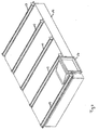
- FIG. 4 shows one of the lying below the lower strand 3 sections of the lower leads 12, 16 from FIG. 1 and FIG. 3 furthermore representative of all heating systems of both the lower and the upper belt.
- This section consists essentially of a cuboid hollow body 12 with a rectangular inlet opening 17 to the side of the double belt system.
- the heated air flow flows substantially horizontally and is limited by the hollow body 12, in particular in the longitudinal direction and to the sides of the double belt system out.
- the hollow body 12 On the side facing the lower run 3, the hollow body 12 has five slot-like outlet openings in the form of nozzles 13, which accelerate the air flow from the interior of the hollow body 12 vertically upwards onto the link plates 1.
- the vertically directed upward to the tape acceleration of the air flow takes place here by the positive pressure within the cuboid hollow body 12 due to the air supply through the blower 10 and by the taper of the slit nozzles 13 in the direction of its outlet opening.
- the slot nozzles 13 From the hollow body 12 so five air streams through the slot nozzles 13 to accelerate to at least 20 m / s and hit the about 3 cm - 8 cm above the nozzle openings extending link plates 1.
- the slot nozzles 13 have such a length, namely about the Width of the band, that the exiting air streams each extend to the entire width of a link plate 1.
- the slot nozzles 13 are spaced in the transport direction and each extend horizontally and perpendicular to this direction.
- a link plate 1 in Operation of the band successively each subjected to a flow of air from each one of these slot nozzles 13 and heated so. Due to the high exit velocity of the air streams from the slot nozzles 13 and the small distance between the nozzles 13 and the link plate 1, the air flow impinges at high speed on the link plate 1 and causes a high heat transfer.
- the double-belt installation In order to return the air streams emerging between the cuboid hollow body 12 and the lower run 3 to the blower 10, the double-belt installation has on its sides the edges 7, 8, 21 of the strip (see FIG. FIG. 2 ), which prevents leakage of air flows laterally out of the system, so that a circuit between the link plates 1 is formed therethrough.
- this panel 7, 8, 21 is lined with a thermally insulating material 25 between the legs of its profile.
- the panel 7, 8, 21 is also used in conjunction with the band surrounding the panel 20 for thermal insulation against both convection and heat conduction.
- a further, additional outer lining (not shown), in particular also of the insulating material 25, can also assist in sealing the space enclosed by the bands against escaping air streams straight out of the area of the strip edges.
- FIG. 5 shows a further section of the double belt system representative in the region of the lower band, in which between the Trumen 2, 3 an infrared heater 30 is attached.
- the upper portion of the double belt system has a corresponding, but up / down-exchanged, infrared heating, which is not shown.
- the infrared heater 30 includes two heating elements each having nine electrically driven infrared radiators 31, the radiation of which is directed respectively to the inside of the link plates 1 of the lower run 3 of the lower band and the upper run 23 of the upper band (not shown).
- the insides of the link plates 1 are covered with an infrared-absorbing layer.
- the link plates 1 are here directly after the tape outlet, the band deflecting connection of the strands 2, 3 (not shown), heated, ie at a tape position, the closest possible from a next possible contact of the link plates 1 with the product, so the to be produced plate materials, is removed, so that enough time remains in the movement of the tapes to transport the heat introduced by heat radiation to the inside of the link plates 1 heat by conduction to the outside of the link plates 1 and also achieve a uniform heat distribution on the outsides.
- the double-belt system thus has the three said differently acting heating mechanisms, namely directed by nozzles 13 on the outer surfaces of the link plates 1 air streams, the blowing of heated air into the space between the dreams 2, 3, 22, 23 and the infrared heater 30 of the inner surfaces of the Blade plates 1.
- the hot air heating between the runs 2, 3, 22, 23 is preferably used as a standstill heating, so to maintain a certain operating temperature, but can also be used to heat the system, but with lower power than the other two heating mechanisms.
- the advantage of this heating mechanism is that the bands can remain at rest when heating.
- the two other heating mechanisms, the infrared heaters 30 and the air jet heater, allow in comparison to the standstill heating a heating in a much shorter time, but the belts must be moved.
- the infrared heater 30 can, given a corresponding electrical power deliver a particularly high heat output, so it is used as a so-called booster heater.
- the booster heater for a short warm-up phase can then resort to unused power reserves, without requiring the electrical supply of the entire production system would have larger dimensions.
- only the air nozzle heating is preferably used.
Landscapes
- Engineering & Computer Science (AREA)
- Mechanical Engineering (AREA)
- Life Sciences & Earth Sciences (AREA)
- Manufacturing & Machinery (AREA)
- Wood Science & Technology (AREA)
- Forests & Forestry (AREA)
- Drying Of Solid Materials (AREA)
Priority Applications (1)
| Application Number | Priority Date | Filing Date | Title |
|---|---|---|---|
| EP08011684A EP2138301A1 (fr) | 2008-06-27 | 2008-06-27 | Installation à double bande avec chauffage |
Applications Claiming Priority (1)
| Application Number | Priority Date | Filing Date | Title |
|---|---|---|---|
| EP08011684A EP2138301A1 (fr) | 2008-06-27 | 2008-06-27 | Installation à double bande avec chauffage |
Publications (1)
| Publication Number | Publication Date |
|---|---|
| EP2138301A1 true EP2138301A1 (fr) | 2009-12-30 |
Family
ID=40028987
Family Applications (1)
| Application Number | Title | Priority Date | Filing Date |
|---|---|---|---|
| EP08011684A Withdrawn EP2138301A1 (fr) | 2008-06-27 | 2008-06-27 | Installation à double bande avec chauffage |
Country Status (1)
| Country | Link |
|---|---|
| EP (1) | EP2138301A1 (fr) |
Cited By (3)
| Publication number | Priority date | Publication date | Assignee | Title |
|---|---|---|---|---|
| US20140259733A1 (en) * | 2013-03-15 | 2014-09-18 | U.S. Natural Resources, Inc. | Unidirectional multi-path lumber kilns |
| US9052140B2 (en) | 2013-03-15 | 2015-06-09 | Usnr, Llc | Method for converting existing kiln to multi-pass kiln |
| DE102023110381A1 (de) | 2023-04-24 | 2024-10-24 | Thyssenkrupp Ag | Vorrichtung zum Fördern von prismatischen Batteriezellen, System und Verfahren |
Citations (6)
| Publication number | Priority date | Publication date | Assignee | Title |
|---|---|---|---|---|
| US2975470A (en) * | 1958-01-09 | 1961-03-21 | Tectum Corp | Apparatus for steam treating fibrous panels |
| US3325859A (en) * | 1961-12-04 | 1967-06-20 | Celotex Corp | Apparatus for making rigid mineral fiber panels |
| US3973893A (en) * | 1973-04-26 | 1976-08-10 | Southampton Manufacturing Company, Inc. | Apparatus for continuously manufacturing boards |
| SU1299799A1 (ru) * | 1985-11-04 | 1987-03-30 | Сибирский технологический институт | Пресс дл непрерывного изготовлени древесностружечных плит |
| EP0255596A1 (fr) * | 1986-08-05 | 1988-02-10 | Mitsubishi Rayon Engineering Co., Ltd. | Presse continue |
| DE19635410A1 (de) * | 1996-08-31 | 1998-03-05 | Siempelkamp Gmbh & Co Maschine | Verfahren und Vorrichtung zur Herstellung biologisch abbaubarer Dämmplatten |
-
2008
- 2008-06-27 EP EP08011684A patent/EP2138301A1/fr not_active Withdrawn
Patent Citations (6)
| Publication number | Priority date | Publication date | Assignee | Title |
|---|---|---|---|---|
| US2975470A (en) * | 1958-01-09 | 1961-03-21 | Tectum Corp | Apparatus for steam treating fibrous panels |
| US3325859A (en) * | 1961-12-04 | 1967-06-20 | Celotex Corp | Apparatus for making rigid mineral fiber panels |
| US3973893A (en) * | 1973-04-26 | 1976-08-10 | Southampton Manufacturing Company, Inc. | Apparatus for continuously manufacturing boards |
| SU1299799A1 (ru) * | 1985-11-04 | 1987-03-30 | Сибирский технологический институт | Пресс дл непрерывного изготовлени древесностружечных плит |
| EP0255596A1 (fr) * | 1986-08-05 | 1988-02-10 | Mitsubishi Rayon Engineering Co., Ltd. | Presse continue |
| DE19635410A1 (de) * | 1996-08-31 | 1998-03-05 | Siempelkamp Gmbh & Co Maschine | Verfahren und Vorrichtung zur Herstellung biologisch abbaubarer Dämmplatten |
Cited By (7)
| Publication number | Priority date | Publication date | Assignee | Title |
|---|---|---|---|---|
| US20140259733A1 (en) * | 2013-03-15 | 2014-09-18 | U.S. Natural Resources, Inc. | Unidirectional multi-path lumber kilns |
| US8875414B2 (en) * | 2013-03-15 | 2014-11-04 | Usnr, Llc | Unidirectional multi-path lumber kilns |
| US9052140B2 (en) | 2013-03-15 | 2015-06-09 | Usnr, Llc | Method for converting existing kiln to multi-pass kiln |
| US9482465B2 (en) | 2013-03-15 | 2016-11-01 | Usnr, Llc | Unidirectional multi-path lumber kilns |
| US9964359B2 (en) | 2013-03-15 | 2018-05-08 | Usnr, Llc | Multi-pass lumber kilns |
| DE102023110381A1 (de) | 2023-04-24 | 2024-10-24 | Thyssenkrupp Ag | Vorrichtung zum Fördern von prismatischen Batteriezellen, System und Verfahren |
| WO2024223463A1 (fr) | 2023-04-24 | 2024-10-31 | thyssenkrupp Automation Engineering GmbH | Dispositif destiné au convoyage d'éléments prismatiques de batterie, système et procédé |
Similar Documents
| Publication | Publication Date | Title |
|---|---|---|
| EP2098811B1 (fr) | Tunnel de séchage pour sécher des ébauches, doté d'ouvertures d'air agencées de manière opposée et avec un écart transversal, et module de tunnel pour un tunnel de séchage | |
| DE3528365C2 (fr) | ||
| DE3136107C2 (de) | Verfahren und Vorrichtung zum Verhindern des Wölbens von Glasplatten im rollenbestückten Ofen einer Waagerecht-Temperanlage | |
| DE69002888T2 (de) | Thermischer Konditionierungsofen. | |
| DE102011009693A1 (de) | Kühlmodul und Vorrichtung zum thermischen Behandeln von Substraten | |
| DE20103680U1 (de) | Kühlanlage zum Kühlen von Kautschukbahnen | |
| EP3358957A1 (fr) | Four à transfert de chaleur combiné | |
| DE2907960C3 (de) | Verfahren und Vorrichtung zum kontinuierlichen Wärmebehandeln von vereinzeltem, langgestrecktem metallischen Gut | |
| DE102013000754A1 (de) | Vorrichtung zum Temperieren von Gegenständen | |
| EP2431172B1 (fr) | Module de bloc de chauffage pour la fabrication de verre de sécurité composite | |
| EP2066456B2 (fr) | Procédé de revêtement en poudre de substrats en bois | |
| DE2710467A1 (de) | Verfahren und vorrichtung zum erhitzen von polymerfolienbahnen vor dem ausrecken in querrichtung | |
| DE19836773A1 (de) | Verfahren und kontinuierliche arbeitende Presse zur Herstellung von Holzwerkstoffplatten und Kunststoffplatten | |
| DE19815276B4 (de) | Nachbehandlungsverfahren für einen extrudierten Gegenstand | |
| DE29980018U1 (de) | Vorrichtung zum Herstellen von vernetzten Polyolefinschäumen | |
| DE102010041706A1 (de) | Verfahren zum Betreiben einer Vorrichtung zum direkten oder indirekten Auftrag von flüssigem oder pastösem Auftragsmedium und Vorrichtung | |
| DE10114381A1 (de) | Verfahren zur kontinuierlichen Herstellung von Holzspanplatten und ähnlichen bahnförmigen Plattenwerkstoffen und dafür geeignete Doppelbandpresse | |
| DE2118589A1 (de) | Verfahren und Vorrichtung zum fortlaufenden Umlenken eines Glasbandes in plastischem Zustand | |
| EP0472906B1 (fr) | Procédé et dispositif pour le chauffage de couches extérieures pour la fabrication d'éléments-sandwich à partir de matières plastiques à plusieurs composants | |
| DE2927717C2 (fr) | ||
| DE102013103758B4 (de) | Verfahren zur Herstellung einer thermoplastischen Kunststoffschaumplatte und Luftkühlungsvorrichtung | |
| EP2111962B1 (fr) | Procédé de fabrication d'une plaque d'isolation thermique | |
| DE19836789A1 (de) | Verfahren, Anlage und kontinuierlich arbeitende Prägepresse zur Herstellung von Holzwerkstoffplatten mit strukturierten Oberflächen | |
| EP3499167B1 (fr) | Dispositif de mise en température d'un espace ainsi que procédé de son fabrication | |
| WO2020052828A1 (fr) | Dispositif et procédé de trempe thermique de vitres à l'aide d'un échangeur de chaleur |
Legal Events
| Date | Code | Title | Description |
|---|---|---|---|
| PUAI | Public reference made under article 153(3) epc to a published international application that has entered the european phase |
Free format text: ORIGINAL CODE: 0009012 |
|
| AK | Designated contracting states |
Kind code of ref document: A1 Designated state(s): AT BE BG CH CY CZ DE DK EE ES FI FR GB GR HR HU IE IS IT LI LT LU LV MC MT NL NO PL PT RO SE SI SK TR |
|
| AX | Request for extension of the european patent |
Extension state: AL BA MK RS |
|
| 17P | Request for examination filed |
Effective date: 20100601 |
|
| 17Q | First examination report despatched |
Effective date: 20100708 |
|
| AKX | Designation fees paid |
Designated state(s): AT BE BG CH CY CZ DE DK EE ES FI FR GB GR HR HU IE IS IT LI LT LU LV MC MT NL NO PL PT RO SE SI SK TR |
|
| RAP1 | Party data changed (applicant data changed or rights of an application transferred) |
Owner name: SIEMPELKAMP MASCHINEN- UND ANLAGENBAU GMBH & CO.KG |
|
| STAA | Information on the status of an ep patent application or granted ep patent |
Free format text: STATUS: THE APPLICATION IS DEEMED TO BE WITHDRAWN |
|
| 18D | Application deemed to be withdrawn |
Effective date: 20111202 |