EP0472940A1 - Installation de recuit en continu comportant un four de carburation ou de nitruration - Google Patents
Installation de recuit en continu comportant un four de carburation ou de nitruration Download PDFInfo
- Publication number
- EP0472940A1 EP0472940A1 EP91112903A EP91112903A EP0472940A1 EP 0472940 A1 EP0472940 A1 EP 0472940A1 EP 91112903 A EP91112903 A EP 91112903A EP 91112903 A EP91112903 A EP 91112903A EP 0472940 A1 EP0472940 A1 EP 0472940A1
- Authority
- EP
- European Patent Office
- Prior art keywords
- carburizing
- furnace
- nitriding
- cooling
- steel strip
- Prior art date
- Legal status (The legal status is an assumption and is not a legal conclusion. Google has not performed a legal analysis and makes no representation as to the accuracy of the status listed.)
- Granted
Links
- 238000005121 nitriding Methods 0.000 title claims abstract description 54
- 238000000137 annealing Methods 0.000 title claims abstract description 44
- 238000005255 carburizing Methods 0.000 claims abstract description 125
- 229910000831 Steel Inorganic materials 0.000 claims abstract description 81
- 239000010959 steel Substances 0.000 claims abstract description 81
- 238000001816 cooling Methods 0.000 claims abstract description 68
- 238000010438 heat treatment Methods 0.000 claims abstract description 20
- 238000002791 soaking Methods 0.000 claims abstract description 12
- 229910001209 Low-carbon steel Inorganic materials 0.000 claims abstract description 11
- 239000010960 cold rolled steel Substances 0.000 claims description 15
- 239000007789 gas Substances 0.000 description 34
- 229910052799 carbon Inorganic materials 0.000 description 11
- 230000008859 change Effects 0.000 description 10
- 239000000112 cooling gas Substances 0.000 description 9
- 238000000034 method Methods 0.000 description 9
- OKTJSMMVPCPJKN-UHFFFAOYSA-N Carbon Chemical compound [C] OKTJSMMVPCPJKN-UHFFFAOYSA-N 0.000 description 7
- 238000006243 chemical reaction Methods 0.000 description 7
- 239000000203 mixture Substances 0.000 description 7
- 238000004080 punching Methods 0.000 description 6
- 230000009467 reduction Effects 0.000 description 6
- 230000008569 process Effects 0.000 description 5
- 239000000126 substance Substances 0.000 description 5
- 239000013078 crystal Substances 0.000 description 4
- 239000010410 layer Substances 0.000 description 4
- 239000000463 material Substances 0.000 description 4
- 150000004767 nitrides Chemical class 0.000 description 4
- 230000004044 response Effects 0.000 description 4
- 239000002737 fuel gas Substances 0.000 description 3
- 230000006870 function Effects 0.000 description 3
- 229910019142 PO4 Inorganic materials 0.000 description 2
- 230000007547 defect Effects 0.000 description 2
- 230000006866 deterioration Effects 0.000 description 2
- 230000000694 effects Effects 0.000 description 2
- 230000006872 improvement Effects 0.000 description 2
- NBIIXXVUZAFLBC-UHFFFAOYSA-K phosphate Chemical compound [O-]P([O-])([O-])=O NBIIXXVUZAFLBC-UHFFFAOYSA-K 0.000 description 2
- 239000010452 phosphate Substances 0.000 description 2
- 238000007789 sealing Methods 0.000 description 2
- 238000010008 shearing Methods 0.000 description 2
- 229910000655 Killed steel Inorganic materials 0.000 description 1
- 239000011449 brick Substances 0.000 description 1
- 230000015556 catabolic process Effects 0.000 description 1
- 238000009833 condensation Methods 0.000 description 1
- 230000005494 condensation Effects 0.000 description 1
- 230000007797 corrosion Effects 0.000 description 1
- 238000005260 corrosion Methods 0.000 description 1
- 238000006731 degradation reaction Methods 0.000 description 1
- 230000008021 deposition Effects 0.000 description 1
- 238000009792 diffusion process Methods 0.000 description 1
- 238000009826 distribution Methods 0.000 description 1
- 239000012535 impurity Substances 0.000 description 1
- 238000009434 installation Methods 0.000 description 1
- 238000004519 manufacturing process Methods 0.000 description 1
- 239000011159 matrix material Substances 0.000 description 1
- 150000001247 metal acetylides Chemical class 0.000 description 1
- 238000002156 mixing Methods 0.000 description 1
- 230000004048 modification Effects 0.000 description 1
- 238000012986 modification Methods 0.000 description 1
- 238000010422 painting Methods 0.000 description 1
- 238000005192 partition Methods 0.000 description 1
- 238000001556 precipitation Methods 0.000 description 1
- 238000003825 pressing Methods 0.000 description 1
- 238000010791 quenching Methods 0.000 description 1
- 230000000171 quenching effect Effects 0.000 description 1
- 238000001953 recrystallisation Methods 0.000 description 1
- 238000005096 rolling process Methods 0.000 description 1
- 238000004904 shortening Methods 0.000 description 1
- 239000007787 solid Substances 0.000 description 1
- 239000006104 solid solution Substances 0.000 description 1
- 239000002344 surface layer Substances 0.000 description 1
- 238000003466 welding Methods 0.000 description 1
- 238000004804 winding Methods 0.000 description 1
Images

Classifications
-
- C—CHEMISTRY; METALLURGY
- C23—COATING METALLIC MATERIAL; COATING MATERIAL WITH METALLIC MATERIAL; CHEMICAL SURFACE TREATMENT; DIFFUSION TREATMENT OF METALLIC MATERIAL; COATING BY VACUUM EVAPORATION, BY SPUTTERING, BY ION IMPLANTATION OR BY CHEMICAL VAPOUR DEPOSITION, IN GENERAL; INHIBITING CORROSION OF METALLIC MATERIAL OR INCRUSTATION IN GENERAL
- C23C—COATING METALLIC MATERIAL; COATING MATERIAL WITH METALLIC MATERIAL; SURFACE TREATMENT OF METALLIC MATERIAL BY DIFFUSION INTO THE SURFACE, BY CHEMICAL CONVERSION OR SUBSTITUTION; COATING BY VACUUM EVAPORATION, BY SPUTTERING, BY ION IMPLANTATION OR BY CHEMICAL VAPOUR DEPOSITION, IN GENERAL
- C23C8/00—Solid state diffusion of only non-metal elements into metallic material surfaces; Chemical surface treatment of metallic material by reaction of the surface with a reactive gas, leaving reaction products of surface material in the coating, e.g. conversion coatings, passivation of metals
- C23C8/02—Pretreatment of the material to be coated
-
- C—CHEMISTRY; METALLURGY
- C21—METALLURGY OF IRON
- C21D—MODIFYING THE PHYSICAL STRUCTURE OF FERROUS METALS; GENERAL DEVICES FOR HEAT TREATMENT OF FERROUS OR NON-FERROUS METALS OR ALLOYS; MAKING METAL MALLEABLE, e.g. BY DECARBURISATION OR TEMPERING
- C21D9/00—Heat treatment, e.g. annealing, hardening, quenching or tempering, adapted for particular articles; Furnaces therefor
- C21D9/46—Heat treatment, e.g. annealing, hardening, quenching or tempering, adapted for particular articles; Furnaces therefor for sheet metals
-
- C—CHEMISTRY; METALLURGY
- C21—METALLURGY OF IRON
- C21D—MODIFYING THE PHYSICAL STRUCTURE OF FERROUS METALS; GENERAL DEVICES FOR HEAT TREATMENT OF FERROUS OR NON-FERROUS METALS OR ALLOYS; MAKING METAL MALLEABLE, e.g. BY DECARBURISATION OR TEMPERING
- C21D9/00—Heat treatment, e.g. annealing, hardening, quenching or tempering, adapted for particular articles; Furnaces therefor
- C21D9/52—Heat treatment, e.g. annealing, hardening, quenching or tempering, adapted for particular articles; Furnaces therefor for wires; for strips ; for rods of unlimited length
-
- C—CHEMISTRY; METALLURGY
- C21—METALLURGY OF IRON
- C21D—MODIFYING THE PHYSICAL STRUCTURE OF FERROUS METALS; GENERAL DEVICES FOR HEAT TREATMENT OF FERROUS OR NON-FERROUS METALS OR ALLOYS; MAKING METAL MALLEABLE, e.g. BY DECARBURISATION OR TEMPERING
- C21D9/00—Heat treatment, e.g. annealing, hardening, quenching or tempering, adapted for particular articles; Furnaces therefor
- C21D9/52—Heat treatment, e.g. annealing, hardening, quenching or tempering, adapted for particular articles; Furnaces therefor for wires; for strips ; for rods of unlimited length
- C21D9/54—Furnaces for treating strips or wire
- C21D9/56—Continuous furnaces for strip or wire
- C21D9/561—Continuous furnaces for strip or wire with a controlled atmosphere or vacuum
Definitions
- the present invention relates to a continuous annealing line for cold-rolled steel sheets and, more particularly, to a continuous annealing line having carburizing and nitriding furnaces which are disposed between a heating furnace or a soaking furnace and a cooling furnace and which continuously carbonizes, nitrides or carbonitrides cold-rolled steel sheets.
- Cold-rolled steel sheets produced by such a process involve a problem in that, when such sheets are subjected to a zinc-phosphatizing process conducted as an under-coat treatment, the crystal grains of the film of phosphate become coarse or the precipitation of crystal grains of phosphate is locally failed with the result that the corrosion resistance after painting is reduced to such a level that can hardly be accepted when the sheets are intended for use on automobiles.
- ultra-low-carbon steel tends to have a coarse structure in heat affected zone by welding, with the result that the strength in such zone becomes lower than that in the weld region or matrix.
- ultra-low-carbon steel is inferior to low-carbon Al killed steels in the aspects of strength and fatigue characteristic in welded portion.
- ultra-low-carbon steel which has a high ductility and, hence, large stickiness, tends to exhibit burrs in edges formed by shearing or punching when the shearing or punching is conducted under the same conditions as that for low-carbon Al killed steel.
- the burrs which have come off in the subsequent pressing step tend to cause flaws such as star-like defects.
- Improvement in workability is essentially accompanied by a reduction in the amount of impurity elements to the surface region. Condensation of elements in the steel during annealing is reduced to lower the hardness at the surface of the steel sheet. Therefore, when such a steel sheet is worked by a press, defects tend to be generated in the surface of the steel sheet due to biting of the press die into the surface of the steel sheet and, in the worst case, the steel sheet may be cracked, unless the surfaces of the steel sheet are sufficiently lubricated.
- Japanese Patent Laid-Open No. 47-29230 discloses an apparatus for continuously carburizing or nitriding steel members. This apparatus, however, is intended to treat non-flat members and is not applied to continuous treatment of steel strips.
- Japanese Patent Publication No. 55-26708 corresponding to United States Patent No. 3,950,192, discloses a method for continuously carburizing a low-carbon steel strip.
- the continuous line used in this method has a pre-heating furnace, a carburizing furnace, a soaking furnace and a cooling furnace which are arranged in the mentioned order, in contrast to the present invention.
- the steel strip which has been carburized is heated in the soaking furnace at a temperature falling in austenitization temperature range, thereby causing carbon to be uniformly dispersed throughout the whole steel strip.
- the reaction rate of solid-solution of carbon into steel is determined by the reaction on the surface of the steel sheet, so that a change in the carburization time, which is caused by any change in the velocity of passage of steel sheet in the continuous annealing line, significantly affects the concentration and depth of carburization.
- an object of the present invention is to provide a continuous annealing line which can continuously carburize and/or nitride steel strips, particularly strips of ultra-low-carbon steel, during annealing and which can quickly and highly accurately change the carburizing and nitriding atmospheres in response to any change in the velocity at which the steel strip passes through the annealing line, thereby overcoming the above-described problems of the prior art.
- a continuous annealing line having a heating furnace with or without a soaking furnace connected thereto, for heating a cold-rolled steel sheet continuously supplied thereto, and a cooling furnace for cooling the heated steel sheet, characterized by comprising a carburizing/nitriding furnace provided between the heating furnace or the soaking furnace and the cooling furnace and arranged for continuously carburizing and/or nitriding the steel sheet.
- the carburizing/nitriding furnace is divided into a plurality of zones and control means are provided for controlling the carburizing and/or nitriding atmosphere or the carburizing and/or nitriding temperature in each of such zones.
- the line further comprises a plurality of carburizing/nitriding furnaces each capable of carburizing/nitriding and cooling for conducting a switching between a mode in which said carburizing/nitriding furnaces are used for carburizing/nitriding said steel strip and a mode in which said carburizing/cooling furnaces are used for cooling said steel strip.
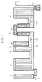
- Fig.1 is a schematic cross-sectional view of a vertical continuous annealing line
- the line is connected at its inlet side to a series of equipments such as an uncoiler, a welder and a rinsing apparatus which are not shown.
- the vertical continuous annealing line has a pre-heating furnace 1, a heating furnace 2, a soaking furnace 3, a carburizing furnace 4, a first cooling furnace 5 and a second cooling furnace 6.
- the vertical continuous annealing line is connected at its outlet side to a series of equipments such as a shear, a coiler and so forth which are not shown.
- the required recrystallization is effected in the heating furnace or the combination of the heating furnace and the soaking furnace and, thereafter, carburizing and/or nitriding are effected while controlling the steel sheet temperature, atmospheric condition, strip moving velocity (furnace residence time) and the cooling condition to provide the desired concentration and depth of carburizing and/or nitriding.
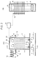
- Fig. 2 shows a carburizing furnace 4 arranged in accordance with the invention between a known soaking furnace 3 and a cooling furnace 5.
- the carburizing furnace 4 has a shell 10 made of refractory bricks and provided with an atmosphere gas supply port 11 formed in one of the walls thereof.
- An atmosphere gas supply pipe 14 having an atmosphere gas flow-rate control valve 12 and an atmosphere gas flowmeter 13 is connected to the gas supply port 11.
- the atmosphere gas supply pipe 14 is branched into component gas pipes which lead to sources of component gases such as CO, CO2, H2 and N2.
- a component gas flow-rate control valve 15 and a component gas flowmeter 16 are provided on the outlet of each component gas source.
- the carburizing furnace 4 is adapted to be supplied with a carburizing gas which has, for example, a composition containing 5 to 10 vol % of CO, 2 to 4 vol % of H2, the ratio CO/CO2 ranging between 15 and 20, and the balance N2.
- the carburizing gas is supplied into the carburizing furnace at a rate which is not less than 1000 Nm3/hr.
- An atmosphere gas discharge port 17 opens in a lower portion of the furnace.
- a radiant tube or a heater denoted by 18 is installed in this furnace.
- a control valve 19 or the like means is provided for controlling the rate of supply of a fuel gas to the radiant tube or electrical current supplied to the heater.
- the temperature in the carburizing furnace is measured by, for example, a pyrometer such as a thermocouple 20.
- control of the carburizing atmosphere in the carburizing furnace 4 includes control of the atmosphere temperature performed by the aforementioned radiant tube or heater 18, control flow rate of the atmosphere gas and control of the composition of the atmosphere gas.
- the velocity of movement of the steel strip 7 is continuously monitored by a velocity sensor 9 and the temperature, flow rate and the composition of the atmosphere gas are controlled automatically through a feedback control conducted on the basis of data stored in a memory table of a computer 21 in accordance with the monitored moving velocity of the steel strip.
- Hearth rolls 8 along which the steel strip 7 is fed are disposed in the carburizing furnace. Sealing devices 22 are provided at the entrance and exit of the carburizing furnace to prevent the carburizing atmosphere gas from leaking outside.
- a steel containing 0.0027 wt% of C, 0.01 wt% of Si, 0.10 wt% of Mn, 0.011 wt% of P, 0.008 wt% of S, 0.041 wt% of A, 0.006 wt% of Nb and the balance Fe and incidental inclusions was prepared in a converter.
- the steel was then continuously cast in an RH gas atmosphere, whereby a continuous steel slab was obtained.
- the slab was heated up to 1200°C and was hot-rolled to a final temperature of 890°C.
- the slab was then taken up at 540°C, whereby a hot-rolled steel strip was obtained.
- the hot-rolled steel strip thus obtained was pickled and cold-rolled at a rolling reduction of 75%, whereby a cold-rolled steel strip of 0.8 mm thick was obtained.
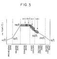
- the temperature range (a) is the range of temperature of the cold-rolled steel strip in the carburizing furnace
- the temperature range (b) is the range of temperature of the cold-rolled strip at the outlet of the carburizing furnace
- the temperature range (c) is the range of temperature of the cold-rolled steel strip in the first cooling furnace
- the temperature range (d) is the range of temperature of the cold-rolled strip at the outlet of the first cooling furnace.
- the carburizing was effected in the carburizing furnace 4 maintaining a carburizing atmosphere gas containing 9.5 vol% of CO, 3.0 vol% of H2 and the balance N2 and supplied at a rate of 1000 Nm3/hr.
- the carburizing temperature and the carburizing time were respectively 780°C and 20 seconds.
- the carburized steel strip was then cooled in the first cooling furnace at a cooling rate of 20°C/sec, until the steel temperature at the outlet of the first cooling furnace comes down to 500°C.
- the same steel strip as that used in this example was continuously annealed without carburizing, for a comparison purpose.
- the continuous annealing line in accordance with the present invention can continuously provide cold-rolled steel sheet which is Table 1 At slab top At slab bottom At slab bottom, without carburization Carburization depth ( ⁇ m) 72 77 - C concentration in condensed layer surface (wt%) 0.010 0.012 (0.003) Number of chemical conversion crystal nucleus (N/4 x 10 ⁇ 6cm ⁇ 2) 102 112 38 Cross tensile strength (Vgf) 406 402 330 Height of burr formed by punching ( ⁇ m) 20 20 60 Friction coefficient ( ⁇ ) 0.17 0.17 0.40 superior in press-formability and chemical conversion treating property.
- the same furnace can be used both as a carburizing furnace and a nitriding furnace by changing the treating atmosphere.
- an (N2 + H2) gas containing NH3 or other mixtures of gas can be used as the nitriding atmosphere.
- the carburizing furnace in the continuous annealing line of the present invention also may be arranged as a carburizing/nitriding furnace in which the steel strip is not only carburized but also nitrided.
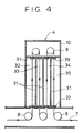
- Figs. 4, 5 and 6 show examples of arrangements which can cope with such a demand.
- the carburizing furnace 4 is divided into a plurality of zones, at least one of which is controlled so that no carburizing gas not nitriding gas is introduced into such a zone, thereby enabling the effective length of the carburizing and nitriding furnace.
- the carburizing furnace is divided by heat-insulating partition walls 31 into four zones: namely, first to fourth zones 32 to 35.
- Sealing devices 36 are provided in the entrance and exit of each zone through which the steel strip 7 moves into and out of the zone, so as to prevent the treating atmospheres in adjacent zones from mixing in each other and to prevent the temperature of treating atmosphere in each zone from being affected by the temperatures of adjacent zones.
- Other portions are materially the same as those shown in Fig. 2.
- the composition and/or the temperature of the carburizing atmosphere is controlled in accordance with the velocity of the steel strip 7 passing through the line.
- the atmosphere gas flow rate control valve 12 for one of the zones is fully closed to terminate the supply of the atmosphere gas to this zone, to reduce the effective length of the line. As a consequence, the time over which the steel strip is subjected to carburizing is shortened to avoid excessive carburizing.
- the atmosphere gas flow rate control valves 12 for one, two or more of the zones are operated in closing direction to reduce the rates of supply of the atmosphere gas, thereby suppressing the tendency for excessive annealing. It is also possible to avoid excessive carburizing by lowering the C potential of the atmosphere gas supplied to one, two or more zones, by changing the composition of the atmosphere gas through operating the flow rate control valves for the respective component gases.
- carburizing can be avoided also by lowering the temperature or temperatures in one, two or more zones, through suitable control of rates of supply of the fuel gas or electric current to the radiant tubes or heaters in these zones. It will be understood that carburizing can be conducted to maintain the required level of carbon concentration and the thickness of the carburized layer regardless of any change in the velocity of movement of the steel strip in the line, by employing one, two or more of the above-described controls. Obviously, the described control or controls can be effected in response to changes in other conditions of the continuous annealing such as changes in the thickness, width and material of the steel strip.
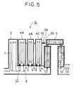
- Fig. 5 shows a sectional view of a carburizing/cooling furnace incorporated in an embodiment of the continuous annealing line of the present invention
- Fig. 6 is a perspective view of a portion of the carburizing/cooling furnace.
- the carburizing/cooling furnace has a plurality of furnaces 4A to 4C.
- a plurality of cooling nozzles 37 and a plurality of radiant tube 18 are alternately arranged at both sides of the steel strip 7.
- the cooling nozzles 37 are arranged such that a cooling gas impinges upon the surfaces of the steel strip 7 substantially at a right angle thereto.
- the cooling nozzles 37 are adapted to be supplied with a cooling gas through a pipe which has a cooling gas flow rate control valve 38 and a cooling gas flowmeter 39.
- Other portions are materially the same as those shown in Fig. 2.
- a velocity sensor 9 continuously monitors the velocity of passage of the steel strip 7.
- a computer 21 functions as a controller which determines whether the furnace 4 is to be used as a carburizing furnace or a cooling furnace on the basis of the content of a memory table set in the memory table and in accordance with the velocity of passage of the steel strip sensed by the velocity sensor 9.
- the control performed by the control means is conducted at a high response speed and with good controllability by changing the composition of the atmosphere gas in each furnace, in such a manner as to obviate any excessive carburizing or insufficiency of carburizing which may otherwise be caused by the change in the velocity of the steel strip passing through the line.
- the switching of the carburizing/cooling furnace between the carburizing mode and the cooling mode is effected by controlling the temperature by the radiant tube 18 and operations of the atmosphere gas flow rate control valve 12 and the cooling gas flow rate control valve 38. For instance, when the carburizing/cooling furnace 4 is switched from the carburizing mode to the cooling mode, the atmosphere gas flow rate control valve 12 is closed and the supply of fuel gas to the radiant tube 18 is stopped, while the cooling gas flow rate control valve 38 is opened to introduce the cooling gas into the furnace 4, whereby the temperature in the furnace 4 is lowered to enable the furnace 4 to function as a cooling furnace.
- the switching between the carburizing mode and the cooling mode is effected for each of the furnaces independently, thus attaining a highly accurate control with a high speed of response to any change in the velocity of the steel strip passing through the line.
- the carburizing/cooling furnace 4 is designed to pass the steel strip 7 vertically, in order to meet the demand for reduction in the installation area.
- the switching of the carburizing/cooling furnace 4 between the carburizing mode and the cooling mode is conducted in accordance with the velocity of the steel strip which passes through this furnace 4.
- the residence time of the steel strip in the carburizing/cooling furnace is increased correspondingly so that the steel strip 7 is excessively carburized unless a suitable measure is taken.
- Such a reduction in the effective length of the carburizing furnace can be attained by switching at least one of the furnaces of the carburizing/cooling furnace 4 into the cooling mode. It is therefore possible to form a carburized layer of a constant thickness regardless of any change in the velocity at which the steel strip passes through the line.
- the switching of the carburizing/cooling furnace between the carburizing mode and the cooling mode may be effected in accordance with changes in other conditions of the continuous annealing, such as changes in thickness, breadth and material of the steel strip.
- the atmosphere of the steel strip in the carburizing/cooling furnace 4 used as a carburizing furnace is controlled to fall within a range between 650 and 900°C. Any steel strip temperature below 650°C reduces the heat-treating efficiency due to a too slow carburization rate. On the other hand, when the steel strip temperature exceeds 900°C, dissolved C is diffused without being fixed in the surface region.
- the temperature distribution in the carburizing furnace is preferably determined so that the difference between the highest and lowest temperatures in this furnace is not greater than 50°C. Deposition of free carbon on the surface of the steel strip causes various problems such as deterioration in the chemical conversion treating property and degradation of the product quality, and hampers subsequent steps of the process.
- the carburizing/cooling furnace 4 when used as the cooling furnace, is controlled as a portion of the subsequent first cooling furnace 5 under the supply of the same atmosphere as that in the first cooling furnace 5. More specifically, the steel strip 7 after the carburizing is cooled quickly through the carburizing/cooling furnace 4 functioning as the cooling furnace and through the first cooling furnace 5, at a cooling rate not smaller than 20°C/sec., until the temperature is lowered to 600°C or below, preferably to 500 to 400°C.
- the rate of the cooling gas blown on the steel strip 7, velocity of the cooling gas, temperature of cooling rolls and winding angle are suitably controlled to realize the above-described cooling effect.
- the cooling is conducted in the first cooling furnace alone when the whole carburizing/cooling furnace is used in carburizing mode.
- a carburizing/nitriding furnace for carburizing and/or nitriding a cold-rolled steel strip is disposed between the heating furnace and the cooling furnace of the continuous annealing line.
- the carburizing/nitriding furnace is sectioned into a plurality of furnaces or is arranged so as to be usable also as a cooling furnace. It is therefore possible to quickly and accurately change the carburizing/nitriding atmosphere and/or the carburizing/nitriding temperature and to obtain a desired effective length of the carburizing/nitriding furnace.
Landscapes
- Chemical & Material Sciences (AREA)
- Engineering & Computer Science (AREA)
- Mechanical Engineering (AREA)
- Materials Engineering (AREA)
- Metallurgy (AREA)
- Organic Chemistry (AREA)
- Physics & Mathematics (AREA)
- Thermal Sciences (AREA)
- Crystallography & Structural Chemistry (AREA)
- Chemical Kinetics & Catalysis (AREA)
- Heat Treatment Of Strip Materials And Filament Materials (AREA)
- Solid-Phase Diffusion Into Metallic Material Surfaces (AREA)
Applications Claiming Priority (6)
| Application Number | Priority Date | Filing Date | Title |
|---|---|---|---|
| JP202833/90 | 1990-07-31 | ||
| JP2202833A JP2502405B2 (ja) | 1990-07-31 | 1990-07-31 | 連続焼鈍炉 |
| JP334149/90 | 1990-11-30 | ||
| JP33414990A JP2954340B2 (ja) | 1990-11-30 | 1990-11-30 | 連続浸炭・浸窒炉及び浸炭・浸窒方法 |
| JP334147/90 | 1990-11-30 | ||
| JP33414790A JP2954339B2 (ja) | 1990-11-30 | 1990-11-30 | 連続焼鈍炉 |
Publications (2)
| Publication Number | Publication Date |
|---|---|
| EP0472940A1 true EP0472940A1 (fr) | 1992-03-04 |
| EP0472940B1 EP0472940B1 (fr) | 1995-03-08 |
Family
ID=27328148
Family Applications (1)
| Application Number | Title | Priority Date | Filing Date |
|---|---|---|---|
| EP91112903A Expired - Lifetime EP0472940B1 (fr) | 1990-07-31 | 1991-07-31 | Installation de recuit en continu comportant un four de carburation ou de nitruration |
Country Status (5)
| Country | Link |
|---|---|
| US (1) | US5192485A (fr) |
| EP (1) | EP0472940B1 (fr) |
| KR (1) | KR940003784B1 (fr) |
| CA (1) | CA2048149C (fr) |
| DE (1) | DE69107931T2 (fr) |
Families Citing this family (8)
| Publication number | Priority date | Publication date | Assignee | Title |
|---|---|---|---|---|
| US6074493A (en) * | 1994-06-15 | 2000-06-13 | Kawasaki Steel Corporation | Method of continuously carburizing metal strip |
| NZ314334A (en) * | 1996-04-19 | 1997-09-22 | Boc Group Inc | Method of heat treating a metal with nitrogen rich gas preheated and then having oxygen-reactive gas added |
| US5795410A (en) * | 1997-01-23 | 1998-08-18 | Usx Corporation | Control of surface carbides in steel strip |
| US20070095434A1 (en) * | 2005-10-28 | 2007-05-03 | Zelim Michael G | Long products, method of thermo-chemical treatment and apparatus |
| DE102010017354A1 (de) | 2010-06-14 | 2011-12-15 | Thyssenkrupp Steel Europe Ag | Verfahren zum Herstellen eines warmgeformten und gehärteten, mit einer metallischen Korrosionsschutzbeschichtung überzogenen Stahlbauteils aus einem Stahlflachprodukt |
| WO2016035345A1 (fr) * | 2014-09-04 | 2016-03-10 | Jfeスチール株式会社 | Procédé de fabrication de tôle d'acier magnétique directionnelle et équipement de traitement de nitruration |
| CN117248176B (zh) * | 2023-10-20 | 2025-11-18 | 钢铁研究总院有限公司 | 一种板带在线连续渗氮装置 |
| CN119824363B (zh) * | 2025-03-18 | 2025-06-03 | 人本股份有限公司 | 用于提高G20CrNi2MoA材料组织性能的热处理方法 |
Citations (4)
| Publication number | Priority date | Publication date | Assignee | Title |
|---|---|---|---|---|
| US2669442A (en) * | 1948-08-24 | 1954-02-16 | Crown Cork & Seal Co | Annealing apparatus |
| FR1234334A (fr) * | 1958-06-27 | 1960-10-17 | Four Industriel Belge | Procédé et installation pour le traitement thermique de fils tréfilés |
| US3950192A (en) * | 1974-10-30 | 1976-04-13 | Monsanto Company | Continuous carburizing method |
| GB1559690A (en) * | 1976-11-10 | 1980-01-23 | British Steel Corp | Treatment of steel products |
Family Cites Families (7)
| Publication number | Priority date | Publication date | Assignee | Title |
|---|---|---|---|---|
| JPS5582723A (en) * | 1978-12-15 | 1980-06-21 | Sumitomo Metal Ind Ltd | Annealing method for cold rolled steel sheet |
| JPS60138065A (ja) * | 1983-12-27 | 1985-07-22 | Chugai Ro Kogyo Kaisha Ltd | ガス浸炭焼入方法およびその連続式ガス浸炭焼入設備 |
| JPS61194119A (ja) * | 1985-02-21 | 1986-08-28 | Nippon Steel Corp | 連続焼鈍設備における鋼帯冷却方法 |
| JP2779170B2 (ja) * | 1988-07-25 | 1998-07-23 | マツダ株式会社 | 浸炭焼入方法 |
| JPH0756043B2 (ja) * | 1988-09-27 | 1995-06-14 | マツダ株式会社 | 鋼部材の製造方法 |
| FR2649123B1 (fr) * | 1989-06-30 | 1991-09-13 | Air Liquide | Procede de traitement thermique de metaux |
| CA2022907C (fr) * | 1989-08-09 | 1994-02-01 | Mitsuru Kitamura | Methode de fabrication d'acier en feuille |
-
1991
- 1991-07-29 KR KR1019910013109A patent/KR940003784B1/ko not_active Expired - Fee Related
- 1991-07-30 CA CA002048149A patent/CA2048149C/fr not_active Expired - Fee Related
- 1991-07-30 US US07/738,231 patent/US5192485A/en not_active Expired - Fee Related
- 1991-07-31 DE DE69107931T patent/DE69107931T2/de not_active Expired - Fee Related
- 1991-07-31 EP EP91112903A patent/EP0472940B1/fr not_active Expired - Lifetime
Patent Citations (4)
| Publication number | Priority date | Publication date | Assignee | Title |
|---|---|---|---|---|
| US2669442A (en) * | 1948-08-24 | 1954-02-16 | Crown Cork & Seal Co | Annealing apparatus |
| FR1234334A (fr) * | 1958-06-27 | 1960-10-17 | Four Industriel Belge | Procédé et installation pour le traitement thermique de fils tréfilés |
| US3950192A (en) * | 1974-10-30 | 1976-04-13 | Monsanto Company | Continuous carburizing method |
| GB1559690A (en) * | 1976-11-10 | 1980-01-23 | British Steel Corp | Treatment of steel products |
Non-Patent Citations (1)
| Title |
|---|
| PATENT ABSTRACTS OF JAPAN, Vol. 9, No. 309 (C-318) 5 December 1985; & JP-A-60 149 729 (KAWASAKI SEITETSU) 7 August 1985, Abstract. * |
Also Published As
| Publication number | Publication date |
|---|---|
| EP0472940B1 (fr) | 1995-03-08 |
| DE69107931T2 (de) | 1995-10-12 |
| CA2048149A1 (fr) | 1992-02-01 |
| CA2048149C (fr) | 1994-03-15 |
| KR940003784B1 (ko) | 1994-05-03 |
| KR920002807A (ko) | 1992-02-28 |
| US5192485A (en) | 1993-03-09 |
| DE69107931D1 (de) | 1995-04-13 |
Similar Documents
| Publication | Publication Date | Title |
|---|---|---|
| US4836774A (en) | Method and apparatus for heating a strip of metallic material in a continuous annealing furnace | |
| EP0276457B1 (fr) | Procédé de fabrication de bandes d'acier galvanisé insensible au vieillissement par immersion | |
| JP2008196015A (ja) | 連続焼鈍設備 | |
| EP0472940B1 (fr) | Installation de recuit en continu comportant un four de carburation ou de nitruration | |
| KR100221789B1 (ko) | 냉연 강판의 연속 소둔 방법 및 설비 | |
| KR950006693B1 (ko) | 연속 소둔로 내의 금속 스트립 상에 가해지는 장력 제어 방법 및 장치 | |
| EP0031012B1 (fr) | Installation pour le recuit en continu de bandes en acier | |
| EP0626467B1 (fr) | Procede permettant de cementer en continu un feuillard d'acier | |
| EP0233944B1 (fr) | Chaine de traitement continue d'acier en bande possedant un four de traitement direct a la flamme | |
| US11414736B2 (en) | Production method of hot-dip galvanized steel sheet | |
| JP2002294351A (ja) | 高強度冷延鋼板の製造方法 | |
| JP2983366B2 (ja) | 連続焼鈍炉における浸炭浸窒処理設備 | |
| EP0360955A2 (fr) | Procédé de fabrication d'une tôle d'acier laminé à froid résistant au vieillissement par recuit continu | |
| EP0803583B2 (fr) | Procédé de refroidissement primaire pour le recuit en continu de bandes d'acier | |
| JP3014603B2 (ja) | 金属帯の連続プラズマ処理装置 | |
| US6074493A (en) | Method of continuously carburizing metal strip | |
| KR100885884B1 (ko) | 소둔로의 가스혼입 방지장치 | |
| JP2954340B2 (ja) | 連続浸炭・浸窒炉及び浸炭・浸窒方法 | |
| JP2954339B2 (ja) | 連続焼鈍炉 | |
| JPH0892712A (ja) | 溶融亜鉛めっき浴への侵入鋼帯の温度制御方法 | |
| EP0495115B1 (fr) | Systeme de refroidissement en continu de feuillards | |
| JPH04202651A (ja) | 連続浸炭・浸窒炉 | |
| JP2006144032A (ja) | 鋼線の伸線・熱処理方法 | |
| EP0211681B1 (fr) | Procédé pour recuire en continu un acier en teneur extra-basse en carbone pour emboutissage profond | |
| JPH06158180A (ja) | 金属帯の連続焼鈍設備 |
Legal Events
| Date | Code | Title | Description |
|---|---|---|---|
| PUAI | Public reference made under article 153(3) epc to a published international application that has entered the european phase |
Free format text: ORIGINAL CODE: 0009012 |
|
| AK | Designated contracting states |
Kind code of ref document: A1 Designated state(s): BE DE ES FR GB |
|
| 17P | Request for examination filed |
Effective date: 19920508 |
|
| 17Q | First examination report despatched |
Effective date: 19940429 |
|
| RBV | Designated contracting states (corrected) |
Designated state(s): DE FR GB |
|
| GRAA | (expected) grant |
Free format text: ORIGINAL CODE: 0009210 |
|
| AK | Designated contracting states |
Kind code of ref document: B1 Designated state(s): DE FR GB |
|
| REF | Corresponds to: |
Ref document number: 69107931 Country of ref document: DE Date of ref document: 19950413 |
|
| ET | Fr: translation filed | ||
| PLBE | No opposition filed within time limit |
Free format text: ORIGINAL CODE: 0009261 |
|
| STAA | Information on the status of an ep patent application or granted ep patent |
Free format text: STATUS: NO OPPOSITION FILED WITHIN TIME LIMIT |
|
| 26N | No opposition filed | ||
| PGFP | Annual fee paid to national office [announced via postgrant information from national office to epo] |
Ref country code: FR Payment date: 20000711 Year of fee payment: 10 |
|
| PGFP | Annual fee paid to national office [announced via postgrant information from national office to epo] |
Ref country code: GB Payment date: 20000726 Year of fee payment: 10 |
|
| PGFP | Annual fee paid to national office [announced via postgrant information from national office to epo] |
Ref country code: DE Payment date: 20000729 Year of fee payment: 10 |
|
| PG25 | Lapsed in a contracting state [announced via postgrant information from national office to epo] |
Ref country code: GB Free format text: LAPSE BECAUSE OF NON-PAYMENT OF DUE FEES Effective date: 20010731 |
|
| GBPC | Gb: european patent ceased through non-payment of renewal fee |
Effective date: 20010731 |
|
| PG25 | Lapsed in a contracting state [announced via postgrant information from national office to epo] |
Ref country code: FR Free format text: LAPSE BECAUSE OF NON-PAYMENT OF DUE FEES Effective date: 20020329 |
|
| PG25 | Lapsed in a contracting state [announced via postgrant information from national office to epo] |
Ref country code: DE Free format text: LAPSE BECAUSE OF NON-PAYMENT OF DUE FEES Effective date: 20020501 |
|
| REG | Reference to a national code |
Ref country code: FR Ref legal event code: ST |