EP0472958A2 - Procédé et dispositif de fabrication d'un talon à apex pour pneus - Google Patents
Procédé et dispositif de fabrication d'un talon à apex pour pneus Download PDFInfo
- Publication number
- EP0472958A2 EP0472958A2 EP91113186A EP91113186A EP0472958A2 EP 0472958 A2 EP0472958 A2 EP 0472958A2 EP 91113186 A EP91113186 A EP 91113186A EP 91113186 A EP91113186 A EP 91113186A EP 0472958 A2 EP0472958 A2 EP 0472958A2
- Authority
- EP
- European Patent Office
- Prior art keywords
- bead
- apex
- ribbon
- inclined surface
- apexed
- Prior art date
- Legal status (The legal status is an assumption and is not a legal conclusion. Google has not performed a legal analysis and makes no representation as to the accuracy of the status listed.)
- Granted
Links
Images


Classifications
-
- B—PERFORMING OPERATIONS; TRANSPORTING
- B29—WORKING OF PLASTICS; WORKING OF SUBSTANCES IN A PLASTIC STATE IN GENERAL
- B29D—PRODUCING PARTICULAR ARTICLES FROM PLASTICS OR FROM SUBSTANCES IN A PLASTIC STATE
- B29D30/00—Producing pneumatic or solid tyres or parts thereof
- B29D30/06—Pneumatic tyres or parts thereof (e.g. produced by casting, moulding, compression moulding, injection moulding, centrifugal casting)
- B29D30/08—Building tyres
- B29D30/10—Building tyres on round cores, i.e. the shape of the core is approximately identical with the shape of the completed tyre
- B29D30/18—Fitting the bead-rings or bead-cores; Folding the textile layers around the rings or cores
-
- B—PERFORMING OPERATIONS; TRANSPORTING
- B29—WORKING OF PLASTICS; WORKING OF SUBSTANCES IN A PLASTIC STATE IN GENERAL
- B29D—PRODUCING PARTICULAR ARTICLES FROM PLASTICS OR FROM SUBSTANCES IN A PLASTIC STATE
- B29D30/00—Producing pneumatic or solid tyres or parts thereof
- B29D30/06—Pneumatic tyres or parts thereof (e.g. produced by casting, moulding, compression moulding, injection moulding, centrifugal casting)
- B29D30/48—Bead-rings or bead-cores; Treatment thereof prior to building the tyre
-
- B—PERFORMING OPERATIONS; TRANSPORTING
- B29—WORKING OF PLASTICS; WORKING OF SUBSTANCES IN A PLASTIC STATE IN GENERAL
- B29D—PRODUCING PARTICULAR ARTICLES FROM PLASTICS OR FROM SUBSTANCES IN A PLASTIC STATE
- B29D30/00—Producing pneumatic or solid tyres or parts thereof
- B29D30/06—Pneumatic tyres or parts thereof (e.g. produced by casting, moulding, compression moulding, injection moulding, centrifugal casting)
- B29D30/48—Bead-rings or bead-cores; Treatment thereof prior to building the tyre
- B29D2030/482—Applying fillers or apexes to bead cores
-
- B—PERFORMING OPERATIONS; TRANSPORTING
- B29—WORKING OF PLASTICS; WORKING OF SUBSTANCES IN A PLASTIC STATE IN GENERAL
- B29D—PRODUCING PARTICULAR ARTICLES FROM PLASTICS OR FROM SUBSTANCES IN A PLASTIC STATE
- B29D30/00—Producing pneumatic or solid tyres or parts thereof
- B29D30/06—Pneumatic tyres or parts thereof (e.g. produced by casting, moulding, compression moulding, injection moulding, centrifugal casting)
- B29D30/48—Bead-rings or bead-cores; Treatment thereof prior to building the tyre
- B29D2030/485—Bead-rings or bead-cores; Treatment thereof prior to building the tyre the bead cores being made using a band containing a plurality of wires embedded in rubber
Definitions
- the present invention relates generally to a bead and apex for a vehicle tire.
- the present invention relates to a method and an apparatus for producing an integral bead and apex unit.
- U.S. Patent No. 1,809,106 discloses a bead ribbon having a bead portion with rubber located about parallel extending bead wires. A strip of rubber extends laterally outwardly and upwardly from one edge of the bead portion.
- the bead ribbon is wound spirally about itself a plurality of times to form a bead core ring.
- the bead core ring is placed around a carcass ply that is supported on a drum in a cylindrical form.
- the rubber strips extend axially inward along the carcass ply. The end of the carcass ply is then turned over the bead core ring.
- the assembly is then removed from the drum.
- the entire bead core ring is turned 90 degrees.
- the agglomeration of rubber formed by the rubber strips extend from the same surface of the bead portion that the rubber strips extended from originally. However, the agglomeration now forms a radially oriented apex.
- U.S. Patent No. 4,168,193 discloses forming a wire bead ring.
- the bead ring is then placed in a mold.
- a cavity in the mold is injected with unvulcanized rubber to form a bead assembly with an apex portion extending substantially radially of the bead ring.
- Bead and apex assemblies such as those referenced above, have certain disadvantages.
- a bead that is typically used today is substantially inextensible and is extremely difficult to turn through a 90 degree angle.
- modern radial tire building operations and machines have been adapted to accept the relatively inextensible beads which are not turned any appreciable amount during construction of a vehicle tire.
- injecting uncured rubber about a bead ring requires an additional manufacturing step, additional handling and additional capital equipment in the form of the injection molding apparatus. All of these additions can be costly to the forming of an apexed bead.
- the present invention is directed to a method and apparatus for making an apexed bead for a vehicle tire.
- the method of making the apexed bead for a tire comprises the steps of providing a supply of rubber and a supply of bead wire.
- the rubber is extruded around at least one bead wire.
- An apex leaf projects from the rubber extruded around the bead wire to form an elongate and substantially continuous ribbon.
- the apex leaf extends in a lateral direction relative to the extent of the bead wire.
- the apex leaf is located between a pair of planes extending coextensively with a pair of respective major side surfaces of a bead portion of the bead ribbon.
- the bead ribbon is wound spirally at least once about itself to form a bead. Radially adjacent apex leafs contact each other to form an integral apex extending laterally from the bead.
- the apparatus for forming the apexed bead includes a cylindrical surface for supporting the bead during a spiral winding operation.
- a frustoconical surface is located concentric with and axially adjacent to the cylindrical surface for supporting a radially extreme apex leaf. The frustoconical surface contacts the radial extreme apex leaf so radially adjacent apex leafs contact each other to form the apex.
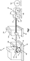
- the bead making apparatus 20 includes a station 42 for delivering prepared bead wire 44 to a rubberizing station 46.
- the rubberizing station 46 deposits uncured rubber around the bead wires 44 and forms a bead ribbon 48.
- the term rubber as used herein is intended to include any natural or synthetic rubber or any combination thereof.
- the bead ribbon 48 is then guided to a bead ring winder 62.
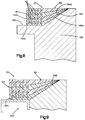
- the bead ring winder 62 spirally winds several layers of bead ribbon 48 (Figs. 8 and 9) about itself to form the hoop-like apexed bead ring 22.
- the finished apexed bead ring 22 is suitable for use in the construction of a vehicle tire.
- the bead wire delivery station 42 includes reels 102 supported for rotation to deliver individual bead wires 44 to the rubberizing station 46.
- the bead wire 44 is preferably steel, but any suitable material may be used to form a substantially inextensible bead ribbon 48. In a preferred embodiment of the invention, five reels 102 of bead wire 44 are illustrated. However, it will be apparent that any suitable number of reels 102 and bead wire 44 may be used for the particular configuration of bead ribbon 48 desired.
- the bead wires 44 are continuously pulled into the rubberizing station 46 in a substantially parallel, equally spaced and planar relationship.
- the bead wires 44 extend in the longitudinal direction to carry load in the substantially continuous and elongate bead ribbon 48.
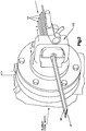
- the rubberizing station 46 includes an extruder head 122, a feeding station 124, and a hopper 126.
- the hopper 126 receives uncured rubber stock and supplies the rubber stock to the feeding station 124.
- the feeding station 124 mixes the rubber stock and delivers the rubber to the extruder head 122 (Fig. 2).
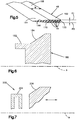
- Uncured rubber 142 (Fig. 3) is deposited around the bead wires 44 as the bead wires are pulled through the extruder head 122. After the rubber 142 is deposited around the bead wires 44, a die portion 144 (Fig. 4) of the extruder head 122 forms the rubberized bead ribbon 48 into a predetermined shape, as illustrated in Fig. 5.
- the bead ribbon 48 includes a bead portion 162 (Fig. 5) which contains the rubberized bead wires 44 and functions as a load carrying portion.
- An apex leaf 164 extends axially or laterally of the bead wires 44 from the bead portion 162.
- the apex leaf 164 is formed integrally as one piece with the bead portion 162.
- the apex leaf 164 has a substantially triangular cross-section taken in a plane extending transverse of the extent of the bead wires 44. It will be apparent that the cross-sectional shape of the apex leaf 164 may be something other than triangular. For example, any cross-sectional shape may be used and is dependent upon the desired shape of the finished apex on the apexed bead ring 22, as is described below.
- the apex leaf 164 is shown to have a pair of equal length legs 166 which are straight. However, it will be apparent that the exact length and shape of each leg 166 would depend on the exact application and final configuration of the apexed bead ring 22 that is desired.
- the apex leaf 164 extends from the bead portion 162 between a pair of planes P1, P2 which are coextensive with and define the limits of opposite major side surfaces 168 of the bead portion.
- the major side surfaces 168 are defined as the surfaces of the bead portion 164 having a transverse dimension (width W) greater than the transverse dimension (thickness T) of the minor side surfaces or edges 170 of the bead portion 162.
- the one piece bead ribbon 48 is formed in a single operation having a bead portion 162 and an apex leaf 164. No additional capital equipment is required to form the bead ribbon 48. Existing equipment can be modified easily to produce the bead ribbon 48.
- the rubber in the bead portion 162 and in the apex leaf 164 are from the same stock and have substantially the same durometer hardness.
- the apex leaf 164 may be made from a rubber having a higher durometer than the durometer of the rubber in the bead portion 162. This may be accomplished by the higher durometer rubber being separately delivered to the extruder head 122 by another or a modified feeding station 124.
- the bead ribbon 48 After the bead ribbon 48 exits the rubberizing station 46 it may be cut off and stored for future use. Preferably, however, the bead ribbon 48 is directed to the bead ring winder 62 where the bead ribbon is spirally wound into the finished hoop-like apexed bead ring 22, as illustrated in Fig. 8. Typically, the bead ribbon 48 will pass between pull drums (not shown) and a through festooner (not shown), both of which are located between the rubberizing station 46 and the bead ring winder 62.
- the bead ring winder 62 includes a specially shaped forming wheel 180, as illustrated in Figs. 6 or 7 which receives and supports the bead ribbon 48 to shape the finished apexed bead ring 22.
- a cylindrical surface 182 (Figs. 6 and 8) receives and supports the bead portion 162 of the bead ribbon 48 to form a bead 84.
- the forming wheel 180 is rotatable about its longitudinal central axis A. The forming wheel 180 is driven to rotate a plurality of revolutions in order to spirally wind the bead ribbon 48 about itself an appropriate number of predetermined times.
- Spiral winding as used herein means the buildup of bead ribbon 48 substantially only in the radial direction relative to the axis A.
- An inclined surface 184 of the forming wheel 180 engages the radially innermost apex leaf 164a.
- the inclined surface 184 preferably is frustoconical.
- the inclined surface 184 forces the innermost apex leaf 164a radially outward of the axis A.
- the next radially outward apex leaf 164b will be deposited on the innermost apex leaf 164a to form an apex 86 extending laterally of the bead 84.
- the winding will continue until the desired finished shape of the apexed bead ring 22 is attained.
- the finished shape of the apex 86 is preferably substantially triangular in cross-section, taken in a plane transverse to the bead wires 44. It will be apparent that the apex 86 may be formed in other shaped.
- the inclined surface 184 may have another shape other than frustoconical, depending on the desired shape of the finished apex 86 of the apexed bead ring 22.
- the inclined surface 184 may be cup-shaped if a curved surface on the apex 86 is desired.
- an apex is used to space apart portions of sheet material used in tire construction as the sheet material is turned around a bead.
- the finished apexed bead ring 22 having an integral apex 86 extending substantially axially or laterally from the bead 84 is provided.
- the bead ribbon 48 is severed by a cut-off apparatus 188 (Fig. 1).
- the apexed bead ring 22 is then removed from the forming wheel 180 by moving the apexed bead axially to the left as viewed in Fig. 8. It will be apparent that the angle and length that the apex 86 extends from the bead 84 can be changed.
- the angle of the apex 86 can be changed by changing the angle on the surface 184 of the forming wheel 180.
- the length of the apex 86 can be changed by providing a longer apex leaf 164 on the bead ribbon 48.
- the newly cut leading edge of the bead ribbon 48 is placed on the forming wheel 180.
- the tackiness of the contacting surface of the bead ribbon 48 on the forming wheel 180 is sufficient so that friction between the bead ribbon and the forming wheel pulls the bead ribbon onto the forming wheel during rotation of the forming wheel.
- FIG. 7 illustrates a forming wheel made 202 from two parts.
- the forming wheel 202 includes a cylindrical surface 204 for supporting the bead portion 162 of the bead ribbon 48.
- An inclined surface 206 is provided and is movable axially relative to the cylindrical surface 204.
- the inclined surface 206 is preferably frustoconical.
- the surfaces 204 and 206 are concentric and driven rotatably about the axis A, in the same manner that the forming wheel 180 described above is driven, to spirally wind successive layers of bead ribbon 48 about itself to form a finished apexed bead ring 22, as illustrated in Fig. 9.
- the inclined surface 206 is moved axially to the right as viewed in Fig. 9 an appropriate amount.
- the appropriate amount is at least slightly larger than the width of the apexed bead ring 22.
- the apexed bead ring 22 can be moved axially off the surface 204 and may then be radially moved between the surfaces 204 and 206. It will be apparent that the inclined surface 206 is supported for rotation from the right side as viewed in Fig. 9 whereas the cylindrical surface 204 is supported for rotation from the left side as viewed in Fig. 9 to allow the apexed bead ring 22 to be removed from the forming wheel 202.
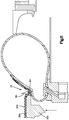
- a machine used for a first stage radial tire building operation includes a drum end 302 (Fig. 10) which is radially expandable and contractable.
- the drum end 302 is illustrated in Fig. 10 in its contracted position and supports an innerliner 304 and a carcass ply layer 306.
- the apexed bead ring 22 is placed radially about the carcass ply layer 306, as illustrated in Fig. 10.
- the apexed bead ring 22 is positioned so that the apex 86 is located to extend from an axially surface or edge of the bead 84.
- the apex 86 is positioned in an unconventional orientation from the apexes of the prior art.
- the drum end 302 is expanded radially outward to the position illustrated in Fig. 11.
- the apex 86 of the apexed bead ring 22 is forced to move or "flow" because it is made of a relatively soft rubber material.
- the apex 86 moves from an axial or lateral orientation relative to the bead 84 into a radial orientation relative to the bead so that the apex now contacts and extends from a radial outermost surface or edge of the bead.
- Some movement or "flow" of the apex 86 may occur in subsequent operations as well, for example during a second stage building operation or during curing.
- the bead 84 of the apexed bead ring 22 has not turned at all during the tire build operation.
- the bead 84 is illustrated as having four layers of bead ribbon 48.
- Each layer of bead ribbon 48 has five bead wires 44.
- Fig. 11 it will be noted that the four layers of bead ribbon 48 in the bead 84 have not reoriented. Specifically, the bead 84 has not turned through a 90° angle.
- the outer edge or end of the carcass ply layer 306 and of the inner liner 304 are turned over the apexed bead ring 22, as is known, to form a cylindrical assembly for use during a second stage tire building operation.
- the tackiness of the layers 304,306 and the apexed bead ring 22 allow the parts of the assembly to maintain their relative positions throughout subsequent operations that will be performed before the tire is cured.
Landscapes
- Engineering & Computer Science (AREA)
- Mechanical Engineering (AREA)
- Tyre Moulding (AREA)
- Gasket Seals (AREA)
- Package Closures (AREA)
- Moulds For Moulding Plastics Or The Like (AREA)
- Extrusion Moulding Of Plastics Or The Like (AREA)
- Tires In General (AREA)
- Manufacturing Of Electric Cables (AREA)
- Details Of Garments (AREA)
- Image Generation (AREA)
Applications Claiming Priority (2)
| Application Number | Priority Date | Filing Date | Title |
|---|---|---|---|
| US57433590A | 1990-08-28 | 1990-08-28 | |
| US574335 | 1990-08-28 |
Publications (3)
| Publication Number | Publication Date |
|---|---|
| EP0472958A2 true EP0472958A2 (fr) | 1992-03-04 |
| EP0472958A3 EP0472958A3 (en) | 1993-03-03 |
| EP0472958B1 EP0472958B1 (fr) | 1996-05-15 |
Family
ID=24295674
Family Applications (1)
| Application Number | Title | Priority Date | Filing Date |
|---|---|---|---|
| EP91113186A Expired - Lifetime EP0472958B1 (fr) | 1990-08-28 | 1991-08-06 | Procédé et dispositif de fabrication d'un talon à apex pour pneus |
Country Status (10)
| Country | Link |
|---|---|
| EP (1) | EP0472958B1 (fr) |
| JP (1) | JPH04251733A (fr) |
| KR (1) | KR0157988B1 (fr) |
| AT (1) | ATE138012T1 (fr) |
| CA (1) | CA2049598A1 (fr) |
| DE (1) | DE69119512T2 (fr) |
| DK (1) | DK0472958T3 (fr) |
| ES (1) | ES2087191T3 (fr) |
| GR (1) | GR3019930T3 (fr) |
| MX (1) | MX9100827A (fr) |
Cited By (2)
| Publication number | Priority date | Publication date | Assignee | Title |
|---|---|---|---|---|
| EP1582334A1 (fr) * | 2004-04-01 | 2005-10-05 | The Goodyear Tire & Rubber Company | Procédé et dispositf pour la formation d'un talon de pneu |
| EP1683628A4 (fr) * | 2003-10-07 | 2008-08-06 | Bridgestone Corp | Procede de fabrication de pneus, appareil de moulage de talons predefinis et systeme de moulage de talons predefinis |
Families Citing this family (2)
| Publication number | Priority date | Publication date | Assignee | Title |
|---|---|---|---|---|
| KR100593020B1 (ko) * | 2004-08-24 | 2006-06-26 | 금호타이어 주식회사 | 타이어 비드 어셈블리 제조용 로터리 사출성형장치 |
| JP7676974B2 (ja) * | 2021-06-09 | 2025-05-15 | 住友ゴム工業株式会社 | ビードワイヤ案内部材及びゴム付きビードワイヤの製造方法 |
Family Cites Families (5)
| Publication number | Priority date | Publication date | Assignee | Title |
|---|---|---|---|---|
| US1809106A (en) * | 1929-08-10 | 1931-06-09 | Lee Rubber & Tire Corp | Tire bead and method of making same |
| US2902083A (en) * | 1955-03-03 | 1959-09-01 | Nat Standard Co | Method of manufacturing tire beads |
| DE2810847A1 (de) * | 1977-03-14 | 1978-09-21 | Kanai Hiroyuki | Wulsteinlage fuer reifen |
| US4795522A (en) * | 1985-04-02 | 1989-01-03 | The Firestone Tire & Rubber Company | Bead filler applicator |
| GB8726628D0 (en) * | 1987-11-13 | 1987-12-16 | Holroyd Associates Ltd | Bead filler construction |
-
1991
- 1991-08-06 DE DE69119512T patent/DE69119512T2/de not_active Expired - Fee Related
- 1991-08-06 EP EP91113186A patent/EP0472958B1/fr not_active Expired - Lifetime
- 1991-08-06 DK DK91113186.0T patent/DK0472958T3/da active
- 1991-08-06 AT AT91113186T patent/ATE138012T1/de not_active IP Right Cessation
- 1991-08-06 ES ES91113186T patent/ES2087191T3/es not_active Expired - Lifetime
- 1991-08-21 CA CA002049598A patent/CA2049598A1/fr not_active Abandoned
- 1991-08-22 JP JP3210710A patent/JPH04251733A/ja active Pending
- 1991-08-27 KR KR1019910014837A patent/KR0157988B1/ko not_active Expired - Fee Related
- 1991-08-27 MX MX9100827A patent/MX9100827A/es unknown
-
1996
- 1996-05-16 GR GR960401293T patent/GR3019930T3/el unknown
Cited By (2)
| Publication number | Priority date | Publication date | Assignee | Title |
|---|---|---|---|---|
| EP1683628A4 (fr) * | 2003-10-07 | 2008-08-06 | Bridgestone Corp | Procede de fabrication de pneus, appareil de moulage de talons predefinis et systeme de moulage de talons predefinis |
| EP1582334A1 (fr) * | 2004-04-01 | 2005-10-05 | The Goodyear Tire & Rubber Company | Procédé et dispositf pour la formation d'un talon de pneu |
Also Published As
| Publication number | Publication date |
|---|---|
| KR0157988B1 (ko) | 1999-01-15 |
| ATE138012T1 (de) | 1996-06-15 |
| MX9100827A (es) | 1992-04-01 |
| DK0472958T3 (da) | 1996-09-16 |
| EP0472958A3 (en) | 1993-03-03 |
| ES2087191T3 (es) | 1996-07-16 |
| DE69119512D1 (de) | 1996-06-20 |
| DE69119512T2 (de) | 1996-11-28 |
| KR920004133A (ko) | 1992-03-27 |
| GR3019930T3 (en) | 1996-08-31 |
| CA2049598A1 (fr) | 1992-03-01 |
| JPH04251733A (ja) | 1992-09-08 |
| EP0472958B1 (fr) | 1996-05-15 |
Similar Documents
| Publication | Publication Date | Title |
|---|---|---|
| US6702913B2 (en) | Method and apparatus for manufacturing a reinforcing structure for tyres of vehicles | |
| RU2213008C2 (ru) | Способ изготовления шины (варианты) | |
| JP3370282B2 (ja) | タイヤ用ゴム部材及びそれを用いたタイヤ | |
| EP1418043B1 (fr) | Procédé et dispositif pour la fabrication d'un élément annulaire en caoutchouc pour pneumatiques | |
| EP0919406B1 (fr) | Bandage pneumatique pour roues de véhicules | |
| US4283241A (en) | Method of producing a tire for a pneumatic tire arrangement | |
| US4929292A (en) | Method for the manufacture of a pneumatic tire | |
| JP2009534230A (ja) | タイヤ、特に空気タイヤ用のトレッドを製造するための方法 | |
| JPH09323504A (ja) | エラストマ製品用の補強プライ及びその製造方法 | |
| EP1488914B1 (fr) | Procédé de fabrication d'un pneu | |
| JP4381609B2 (ja) | 自動車用タイヤのカーカス構造体の製造方法、及びそのカーカス構造体 | |
| US5374324A (en) | Apexed bead for a tire | |
| EP0472958B1 (fr) | Procédé et dispositif de fabrication d'un talon à apex pour pneus | |
| EP2229274B1 (fr) | Procédé et appareil de fabrication de pneus pour roues de véhicules | |
| US7479196B2 (en) | Method for manufacturing or retreading a pneumatic tire | |
| KR20060116007A (ko) | 차량 바퀴용 타이어 제조를 위한 반제품을 생산하기 위한공정 및 장치 | |
| US6941992B2 (en) | Tire for a vehicle wheel and method of manufacturing the tire | |
| EP2700495A1 (fr) | Procédé et installation pour produire des pneus pour roues de véhicules | |
| US20060108053A1 (en) | Hot application of apex on a tire building machine | |
| GB2207644A (en) | Apparatus for the manufacture of a pneumatic tyre |
Legal Events
| Date | Code | Title | Description |
|---|---|---|---|
| PUAI | Public reference made under article 153(3) epc to a published international application that has entered the european phase |
Free format text: ORIGINAL CODE: 0009012 |
|
| AK | Designated contracting states |
Kind code of ref document: A2 Designated state(s): AT BE CH DE DK ES FR GB GR IT LI LU NL SE |
|
| PUAL | Search report despatched |
Free format text: ORIGINAL CODE: 0009013 |
|
| AK | Designated contracting states |
Kind code of ref document: A3 Designated state(s): AT BE CH DE DK ES FR GB GR IT LI LU NL SE |
|
| 17P | Request for examination filed |
Effective date: 19930702 |
|
| 17Q | First examination report despatched |
Effective date: 19941024 |
|
| RAP1 | Party data changed (applicant data changed or rights of an application transferred) |
Owner name: UNIROYAL GOODRICH LICENSING SERVICES, INC. |
|
| GRAH | Despatch of communication of intention to grant a patent |
Free format text: ORIGINAL CODE: EPIDOS IGRA |
|
| GRAA | (expected) grant |
Free format text: ORIGINAL CODE: 0009210 |
|
| ITF | It: translation for a ep patent filed | ||
| AK | Designated contracting states |
Kind code of ref document: B1 Designated state(s): AT BE CH DE DK ES FR GB GR IT LI LU NL SE |
|
| REF | Corresponds to: |
Ref document number: 138012 Country of ref document: AT Date of ref document: 19960615 Kind code of ref document: T |
|
| REF | Corresponds to: |
Ref document number: 69119512 Country of ref document: DE Date of ref document: 19960620 |
|
| REG | Reference to a national code |
Ref country code: ES Ref legal event code: BA2A Ref document number: 2087191 Country of ref document: ES Kind code of ref document: T3 |
|
| REG | Reference to a national code |
Ref country code: ES Ref legal event code: FG2A Ref document number: 2087191 Country of ref document: ES Kind code of ref document: T3 |
|
| REG | Reference to a national code |
Ref country code: GR Ref legal event code: FG4A Free format text: 3019930 |
|
| ET | Fr: translation filed | ||
| REG | Reference to a national code |
Ref country code: DK Ref legal event code: T3 |
|
| PLBE | No opposition filed within time limit |
Free format text: ORIGINAL CODE: 0009261 |
|
| STAA | Information on the status of an ep patent application or granted ep patent |
Free format text: STATUS: NO OPPOSITION FILED WITHIN TIME LIMIT |
|
| 26N | No opposition filed | ||
| PGFP | Annual fee paid to national office [announced via postgrant information from national office to epo] |
Ref country code: SE Payment date: 19980721 Year of fee payment: 8 |
|
| PGFP | Annual fee paid to national office [announced via postgrant information from national office to epo] |
Ref country code: DK Payment date: 19980722 Year of fee payment: 8 |
|
| PGFP | Annual fee paid to national office [announced via postgrant information from national office to epo] |
Ref country code: AT Payment date: 19980723 Year of fee payment: 8 |
|
| PGFP | Annual fee paid to national office [announced via postgrant information from national office to epo] |
Ref country code: CH Payment date: 19980724 Year of fee payment: 8 |
|
| PGFP | Annual fee paid to national office [announced via postgrant information from national office to epo] |
Ref country code: NL Payment date: 19980728 Year of fee payment: 8 |
|
| PGFP | Annual fee paid to national office [announced via postgrant information from national office to epo] |
Ref country code: BE Payment date: 19980813 Year of fee payment: 8 |
|
| PGFP | Annual fee paid to national office [announced via postgrant information from national office to epo] |
Ref country code: ES Payment date: 19980817 Year of fee payment: 8 |
|
| PGFP | Annual fee paid to national office [announced via postgrant information from national office to epo] |
Ref country code: GR Payment date: 19980819 Year of fee payment: 8 |
|
| PGFP | Annual fee paid to national office [announced via postgrant information from national office to epo] |
Ref country code: LU Payment date: 19980902 Year of fee payment: 8 |
|
| PG25 | Lapsed in a contracting state [announced via postgrant information from national office to epo] |
Ref country code: AT Free format text: LAPSE BECAUSE OF NON-PAYMENT OF DUE FEES Effective date: 19990806 Ref country code: DK Free format text: LAPSE BECAUSE OF NON-PAYMENT OF DUE FEES Effective date: 19990806 Ref country code: LU Free format text: LAPSE BECAUSE OF NON-PAYMENT OF DUE FEES Effective date: 19990806 |
|
| PG25 | Lapsed in a contracting state [announced via postgrant information from national office to epo] |
Ref country code: ES Free format text: LAPSE BECAUSE OF NON-PAYMENT OF DUE FEES Effective date: 19990807 |
|
| PG25 | Lapsed in a contracting state [announced via postgrant information from national office to epo] |
Ref country code: SE Free format text: THE PATENT HAS BEEN ANNULLED BY A DECISION OF A NATIONAL AUTHORITY Effective date: 19990830 |
|
| PG25 | Lapsed in a contracting state [announced via postgrant information from national office to epo] |
Ref country code: LI Free format text: LAPSE BECAUSE OF NON-PAYMENT OF DUE FEES Effective date: 19990831 Ref country code: GR Free format text: LAPSE BECAUSE OF NON-PAYMENT OF DUE FEES Effective date: 19990831 Ref country code: BE Free format text: LAPSE BECAUSE OF NON-PAYMENT OF DUE FEES Effective date: 19990831 Ref country code: CH Free format text: LAPSE BECAUSE OF NON-PAYMENT OF DUE FEES Effective date: 19990831 |
|
| BERE | Be: lapsed |
Owner name: UNIROYAL GOODRICH LICENSING SERVICES INC. Effective date: 19990831 |
|
| PG25 | Lapsed in a contracting state [announced via postgrant information from national office to epo] |
Ref country code: NL Free format text: LAPSE BECAUSE OF NON-PAYMENT OF DUE FEES Effective date: 20000301 |
|
| REG | Reference to a national code |
Ref country code: CH Ref legal event code: PL |
|
| EUG | Se: european patent has lapsed |
Ref document number: 91113186.0 |
|
| NLV4 | Nl: lapsed or anulled due to non-payment of the annual fee |
Effective date: 20000301 |
|
| REG | Reference to a national code |
Ref country code: DK Ref legal event code: EBP |
|
| REG | Reference to a national code |
Ref country code: GB Ref legal event code: IF02 |
|
| REG | Reference to a national code |
Ref country code: ES Ref legal event code: FD2A Effective date: 20000911 |
|
| REG | Reference to a national code |
Ref country code: GB Ref legal event code: 732E |
|
| REG | Reference to a national code |
Ref country code: FR Ref legal event code: CD Ref country code: FR Ref legal event code: TP |
|
| PGFP | Annual fee paid to national office [announced via postgrant information from national office to epo] |
Ref country code: DE Payment date: 20070802 Year of fee payment: 17 |
|
| PGFP | Annual fee paid to national office [announced via postgrant information from national office to epo] |
Ref country code: GB Payment date: 20070801 Year of fee payment: 17 |
|
| PGFP | Annual fee paid to national office [announced via postgrant information from national office to epo] |
Ref country code: IT Payment date: 20070828 Year of fee payment: 17 |
|
| PGFP | Annual fee paid to national office [announced via postgrant information from national office to epo] |
Ref country code: FR Payment date: 20070808 Year of fee payment: 17 |
|
| GBPC | Gb: european patent ceased through non-payment of renewal fee |
Effective date: 20080806 |
|
| REG | Reference to a national code |
Ref country code: FR Ref legal event code: ST Effective date: 20090430 |
|
| PG25 | Lapsed in a contracting state [announced via postgrant information from national office to epo] |
Ref country code: DE Free format text: LAPSE BECAUSE OF NON-PAYMENT OF DUE FEES Effective date: 20090303 Ref country code: IT Free format text: LAPSE BECAUSE OF NON-PAYMENT OF DUE FEES Effective date: 20080806 Ref country code: FR Free format text: LAPSE BECAUSE OF NON-PAYMENT OF DUE FEES Effective date: 20080901 |
|
| PG25 | Lapsed in a contracting state [announced via postgrant information from national office to epo] |
Ref country code: GB Free format text: LAPSE BECAUSE OF NON-PAYMENT OF DUE FEES Effective date: 20080806 |