EP0473042A2 - Douille pour le montage au plafond - Google Patents
Douille pour le montage au plafond Download PDFInfo
- Publication number
- EP0473042A2 EP0473042A2 EP91113900A EP91113900A EP0473042A2 EP 0473042 A2 EP0473042 A2 EP 0473042A2 EP 91113900 A EP91113900 A EP 91113900A EP 91113900 A EP91113900 A EP 91113900A EP 0473042 A2 EP0473042 A2 EP 0473042A2
- Authority
- EP
- European Patent Office
- Prior art keywords
- box
- flush
- fastening
- ceiling
- carrier piece
- Prior art date
- Legal status (The legal status is an assumption and is not a legal conclusion. Google has not performed a legal analysis and makes no representation as to the accuracy of the status listed.)
- Withdrawn
Links
Images




Classifications
-
- F—MECHANICAL ENGINEERING; LIGHTING; HEATING; WEAPONS; BLASTING
- F21—LIGHTING
- F21V—FUNCTIONAL FEATURES OR DETAILS OF LIGHTING DEVICES OR SYSTEMS THEREOF; STRUCTURAL COMBINATIONS OF LIGHTING DEVICES WITH OTHER ARTICLES, NOT OTHERWISE PROVIDED FOR
- F21V21/00—Supporting, suspending, or attaching arrangements for lighting devices; Hand grips
- F21V21/02—Wall, ceiling, or floor bases; Fixing pendants or arms to the bases
- F21V21/03—Ceiling bases, e.g. ceiling roses
Definitions
- the invention relates to a recessed ceiling box, consisting of a flush-mounted box, a carrier piece held therein in a rotationally secured manner with electrical clamping contacts, which are accessible through bores in a cover box screwed against the carrier piece, and a hanging hook projecting through the cover box and pivotably arranged on the carrier piece.
- Such a recessed ceiling box is known from DE-A-30 02 080. It has the task of making the simple and electrically secured mounting of ceiling lights possible by the fixed mounting of a ceiling-side socket. It is intended to fix the flush-mounted box directly to the surface with screws.
- the carrier piece is fastened with a base plate in the flush-mounted box.
- the cover box is held on this again.
- a carrier piece insert is provided in the carrier piece, on which a ceiling hook which is approximately Y-shaped at the end is pivotably held. This ceiling hook protrudes outwards through the cover box and can be pivoted flat against the outside of the cover box when not in use and perpendicular to the cover box in the user position arranged.
- the object of the invention is to simplify the construction of such a recessed ceiling box, in particular with regard to assembly, and to expand its possible uses.
- the receptacle for the hanging hook forms at the same time the fixing of the carrier piece against the flush-mounted box to be fastened to a ceiling in the ceiling installation box according to the invention.
- the ceiling hook can be easily installed in this receptacle, which is designed as a fastening tab, and is securely held therein after the installation of the entire installation box.
- the associated cover box is attached to the carrier piece. It is thus designed together with the carrier piece, which carries the electrical clamping contacts, as a unit and can therefore also be axially set up in certain applications.
- Such a device is required if the associated flush-mounted box should be able to be placed on the formwork for concrete ceilings and it is necessary to adapt the entire height of the mounting box to the thickness of the plaster to be applied to the concrete ceiling later.
- a recessed ceiling box according to claim 7 is used.
- the corresponding associated flush-mounted box can be placed on the formwork of a concrete ceiling with the insert recessed inwards and fixed with nails which are guided through the outer fastening approaches according to claim 10, and then poured into concrete. After the pouring and removal of the formwork, the ends of the nails or corresponding sleeve nails are removed.
- the insert accommodated in the flush-mounted box is set up on the outside and thus also serves as a cleaning gauge.
- the outer plaster level is flush with the front of the insert.
- the carrier piece with the overlapping tab-like receiving part, which carries the pivotable suspension hook, can be fixed with corresponding fastening screws according to claim 8 against the flush-mounted box.
- the counter support forms the bottom of the insert, which is perforated centrally in accordance with claim 8.
- the insert is cylindrical and can be set up in the axial direction in a simple manner with an external thread in an internal thread in the edge of the flush-mounted box.
- the invention also includes the proposal, according to claim 10, to provide line entries or corresponding pipes through the outer lugs on the flush-mounted box in the direction perpendicular thereto.
- the features of claim 2 lead to a rotation-proof connection of the support piece and the suspension hook in connection with the attachment to the flush-mounted box.
- the ceiling mounting box according to claim 3 shows a favorable attachment of the hanging hook.
- the fastening tab according to claim 4 takes up the protective conductor contacts.
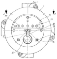
- the illustrated ceiling installation box for the plug connection of lights or the like has a flush-mounted box 102 which can be fastened to the formwork of a concrete ceiling, not shown, in which an insert is provided which can be set up in the axial direction.
- an insert is provided which can be set up in the axial direction.
- This carrier piece 3 is fixed to the flush-mounted box 102 by means of cap screws 7 using a separate fastening tab 4.
- the fastening tab 4 pivots on the suspension hook 5.
- the cover box 1 can be fixed, through which, as can be seen from FIG. 1, the hanging hook 5 projects.
- a concentric shoulder 11 is formed with the bores 111 for carrying out the contacts of an associated plug part, not shown.
- the paragraph 15 formed is used to snap a flat cover part, not shown, with which the cover box is closed when not in use.
- the hanging hook 5 protrudes through the T-shaped opening 12 of the cover box 1 and lies flat in the depression 16 in the non-use position. Sockets of a corresponding spot can be fixed through the bores 13.
- the flush-mounted box 102 which can be seen particularly in FIGS. 2 and 7, has an upper edge 21 with an internal thread 215.
- threaded sleeves 221 are formed at a corresponding distance from one another, into which the fastening screws 7 protrude.
- the shoulder formed between the edge 21 and the rest of the box section bears the number 211.
- several lugs 212 are formed with axially parallel bores 213 for carrying out fastening nails or screws. These holes 213 are outside the circumference of the cover box 1. Transversely to the axial direction of the flush-mounted box 102 are in the outer approaches 212 cable entries 214 are provided.
- this insert is first unscrewed to match the plaster thickness. Then the support piece 3 is inserted and fastened via the fastening tab 4 and the cap screws 7. Finally, the cover box 1 is fastened to the support piece 3 with screw fastenings.
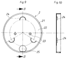
- a ceiling installation box according to FIGS. 8-10 is placed and plastered on the building ceiling, not shown.
- Your flush-mounted box is marked with the number 2. They has an edge 21 and a bottom 22 in which holes 23 are provided for attachment.
- This flush-mounted box 2 also takes a carrier piece 3 made of plastic with the cover box 1 which can be fixed thereon and a hinged hanging hook 5 which projects through the cover box 1 to the outside in accordance with the embodiment of the previously described ceiling installation box.
- the securing against rotation and the exact positioning of the carrier piece 3 used is achieved, which partially rests on the half-ring webs 24 with correspondingly arranged cylinder web sections 31, 32 and 33.
- the opening 25 serves for the insertion of the electrical line on the ceiling.
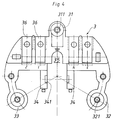
- the flat carrier piece 3 has chambers 36 for receiving electrical contacts (not shown).
- two webs 34 are formed at a distance from one another in parallel, and chambers 341 are formed on their mutually facing walls.
- the correspondingly bent mounting tab 4 is preferably attached by clamping.
- Its central flat part 41 has a terminal formation 412 at one end and a threaded bore 411 at the other end for connecting a protective conductor.
- the U-shaped bends 42 are formed, which cover the webs 34 of the carrier piece 3.
- the fastening arms 43 in which bores 431 are provided which project with the arrangement of the two bores 23 and the flush-mounted box 2, are integrally formed on these two offsets 42, projecting outwards. With this fastening tab 4, the carrier piece 3 is fastened to the ceiling together with the flush-mounted box 2 with screws which are passed through the bores 43.
- the cover box 1 is fastened to the support piece with screw connections which are passed through the holes 14 and engage in the holes 311 and 312 in the support piece 3.
- the Fastening tab 4 with lateral openings 422 on cams 342 on the webs 34 of the support piece 3 can be locked.
- the flat cover plate can be snapped into the cover box 1 on the inside of its box with an internal thread or the like, in the manner of a canopy.
Landscapes
- Engineering & Computer Science (AREA)
- General Engineering & Computer Science (AREA)
- Forms Removed On Construction Sites Or Auxiliary Members Thereof (AREA)
- Connection Or Junction Boxes (AREA)
Applications Claiming Priority (2)
| Application Number | Priority Date | Filing Date | Title |
|---|---|---|---|
| DE9012349U DE9012349U1 (de) | 1990-08-29 | 1990-08-29 | Deckeneinbaudose |
| DE9012349U | 1990-08-29 |
Publications (2)
| Publication Number | Publication Date |
|---|---|
| EP0473042A2 true EP0473042A2 (fr) | 1992-03-04 |
| EP0473042A3 EP0473042A3 (en) | 1992-12-09 |
Family
ID=6856941
Family Applications (1)
| Application Number | Title | Priority Date | Filing Date |
|---|---|---|---|
| EP19910113900 Withdrawn EP0473042A3 (en) | 1990-08-29 | 1991-08-20 | Socket for ceiling-mounting |
Country Status (2)
| Country | Link |
|---|---|
| EP (1) | EP0473042A3 (fr) |
| DE (1) | DE9012349U1 (fr) |
Cited By (4)
| Publication number | Priority date | Publication date | Assignee | Title |
|---|---|---|---|---|
| EP1109270A3 (fr) * | 1999-12-14 | 2002-12-18 | Ensto Busch-Jaeger Oy | Prise de courant pour un dispositif d'éclairage |
| WO2004012315A1 (fr) * | 2002-07-23 | 2004-02-05 | Moeller Gebäudeautomation KG | Boitier d'actionneur |
| EP2624391B1 (fr) * | 2012-02-01 | 2015-07-01 | Abb B.V. | Assemblage d'un câblage électrique et pièce auxiliaire permettant de construire le câblage électrique |
| US20160258605A1 (en) * | 2013-10-31 | 2016-09-08 | Filuxx Systems Gmbh | Device for the connection of electrical luminaires with fault current diversion |
Families Citing this family (4)
| Publication number | Priority date | Publication date | Assignee | Title |
|---|---|---|---|---|
| DE19700730A1 (de) | 1997-01-11 | 1998-07-16 | Hans Fischer | Deckensteckdose für Deckenleuchten |
| DE19702395A1 (de) * | 1997-01-24 | 1998-07-30 | Walter Schneider | Vorrichtung zum Aufhängen einer elektrisch betriebenen Lampe |
| DE19805034A1 (de) * | 1998-02-09 | 1999-08-12 | Colin Johnson | Steckanschluß für Deckenlampen |
| DE102014207103A1 (de) * | 2014-04-14 | 2015-10-15 | Robert Lorenz | Leuchtenanschlussdose |
Family Cites Families (3)
| Publication number | Priority date | Publication date | Assignee | Title |
|---|---|---|---|---|
| DE2730859A1 (de) * | 1977-07-08 | 1979-01-25 | Alfred Schweiger | Vorrichtung zum aufhaengen von wand- oder deckenleuchten |
| DE3002080A1 (de) * | 1980-01-22 | 1981-07-23 | Hans Fischer | Montagesatz fuer den mechanischen und elektrischen anschluss einer pendelleuchte |
| DE8910140U1 (de) * | 1989-08-24 | 1989-10-12 | Fischer, Hans, 5983 Balve | Abdeckung für eine Deckeneinbaudose |
-
1990
- 1990-08-29 DE DE9012349U patent/DE9012349U1/de not_active Expired - Lifetime
-
1991
- 1991-08-20 EP EP19910113900 patent/EP0473042A3/de not_active Withdrawn
Cited By (6)
| Publication number | Priority date | Publication date | Assignee | Title |
|---|---|---|---|---|
| EP1109270A3 (fr) * | 1999-12-14 | 2002-12-18 | Ensto Busch-Jaeger Oy | Prise de courant pour un dispositif d'éclairage |
| WO2004012315A1 (fr) * | 2002-07-23 | 2004-02-05 | Moeller Gebäudeautomation KG | Boitier d'actionneur |
| CN100416957C (zh) * | 2002-07-23 | 2008-09-03 | 穆勒建筑物自动化两合公司 | 致动器 |
| EP2624391B1 (fr) * | 2012-02-01 | 2015-07-01 | Abb B.V. | Assemblage d'un câblage électrique et pièce auxiliaire permettant de construire le câblage électrique |
| US20160258605A1 (en) * | 2013-10-31 | 2016-09-08 | Filuxx Systems Gmbh | Device for the connection of electrical luminaires with fault current diversion |
| US10578286B2 (en) * | 2013-10-31 | 2020-03-03 | Filuxx Systems Gmbh | Device for the connection of electrical luminaires with fault current diversion |
Also Published As
| Publication number | Publication date |
|---|---|
| EP0473042A3 (en) | 1992-12-09 |
| DE9012349U1 (de) | 1990-10-31 |
Similar Documents
| Publication | Publication Date | Title |
|---|---|---|
| EP3384568B1 (fr) | Profilé pour châssis d'armoire électrique et châssis correspondant | |
| DE4433704C2 (de) | Steckbuchse | |
| EP1035371A2 (fr) | Arrangement d'éclairage | |
| DE4342512C2 (de) | Elektrische Einbaudose | |
| DE10355350B4 (de) | Elektromodul | |
| EP0473042A2 (fr) | Douille pour le montage au plafond | |
| DE4432509A1 (de) | Elektro-Installationsgerät, insbesondere für Kabelkanäle | |
| EP0141021B1 (fr) | Douille pour lampe à incandescence | |
| DE19816390A1 (de) | Aufnahmegehäuse für Moduleinheiten einer Türstation einer Türsprechanlage | |
| DE3001574C2 (de) | Verfahren zur Montage elektrischer Installationsgeräte in vorgefertigten Hohlwänden und nach diesem Verfahren montierbare Einbaudose | |
| DE4222656C2 (de) | Elektrische Steckdose | |
| EP0453392B1 (fr) | Canal d'alimentation en énergie électrique | |
| EP0727850A2 (fr) | Dispositif pour le positionnement d'un composant électrique ou électronique dans une boîte | |
| EP3675300B1 (fr) | Adaptateur de positionnement et de fixation d'un boîtier d'installation | |
| DE4005030A1 (de) | Fahrzeugantenne | |
| EP0921595B1 (fr) | Boíte de jonction | |
| CH697561B1 (de) | Anordnung zur Halterung eines Installationsgeräte-Einsatzes an einer Tragplatte. | |
| DE69800965T2 (de) | Gehäuse für elektrische Installation mit Befestigungsvorrichtung für den Deckel und Wandbefestigung | |
| DE19644372B4 (de) | Versatzausgleich für eine Installationsgerätekombination | |
| EP0991158B1 (fr) | Une réception d'appareil pour boítier pour appareillage installé sous plancher | |
| DE4004648C2 (fr) | ||
| DE3639514C2 (de) | Einbaudose, insbesondere Unterputzdose | |
| DE3634311C2 (de) | Montagegehäuse für eine elektrische Einrichtung | |
| EP0675583B1 (fr) | Matériel pour montage en surface d'un élément électrique tel qu'interrupteur, prise ou similaire | |
| DE102004008003B3 (de) | Gehäuseanordnung |
Legal Events
| Date | Code | Title | Description |
|---|---|---|---|
| PUAI | Public reference made under article 153(3) epc to a published international application that has entered the european phase |
Free format text: ORIGINAL CODE: 0009012 |
|
| AK | Designated contracting states |
Kind code of ref document: A2 Designated state(s): AT BE CH DE DK ES FR GB GR IT LI LU NL SE |
|
| PUAL | Search report despatched |
Free format text: ORIGINAL CODE: 0009013 |
|
| AK | Designated contracting states |
Kind code of ref document: A3 Designated state(s): AT BE CH DE DK ES FR GB GR IT LI LU NL SE |
|
| STAA | Information on the status of an ep patent application or granted ep patent |
Free format text: STATUS: THE APPLICATION IS DEEMED TO BE WITHDRAWN |
|
| 18D | Application deemed to be withdrawn |
Effective date: 19930610 |