EP0473112A2 - Verfahren zur Steuerung der dynamischen Eigenschaften eines Kraftfahrzeuges - Google Patents
Verfahren zur Steuerung der dynamischen Eigenschaften eines Kraftfahrzeuges Download PDFInfo
- Publication number
- EP0473112A2 EP0473112A2 EP91114357A EP91114357A EP0473112A2 EP 0473112 A2 EP0473112 A2 EP 0473112A2 EP 91114357 A EP91114357 A EP 91114357A EP 91114357 A EP91114357 A EP 91114357A EP 0473112 A2 EP0473112 A2 EP 0473112A2
- Authority
- EP
- European Patent Office
- Prior art keywords
- vehicle
- parameter
- unit
- wheel
- target value
- Prior art date
- Legal status (The legal status is an assumption and is not a legal conclusion. Google has not performed a legal analysis and makes no representation as to the accuracy of the status listed.)
- Granted
Links
Images



Classifications
-
- B—PERFORMING OPERATIONS; TRANSPORTING
- B62—LAND VEHICLES FOR TRAVELLING OTHERWISE THAN ON RAILS
- B62D—MOTOR VEHICLES; TRAILERS
- B62D6/00—Arrangements for automatically controlling steering depending on driving conditions sensed and responded to, e.g. control circuits
- B62D6/04—Arrangements for automatically controlling steering depending on driving conditions sensed and responded to, e.g. control circuits responsive only to forces disturbing the intended course of the vehicle, e.g. forces acting transversely to the direction of vehicle travel
-
- B—PERFORMING OPERATIONS; TRANSPORTING
- B60—VEHICLES IN GENERAL
- B60T—VEHICLE BRAKE CONTROL SYSTEMS OR PARTS THEREOF; BRAKE CONTROL SYSTEMS OR PARTS THEREOF, IN GENERAL; ARRANGEMENT OF BRAKING ELEMENTS ON VEHICLES IN GENERAL; PORTABLE DEVICES FOR PREVENTING UNWANTED MOVEMENT OF VEHICLES; VEHICLE MODIFICATIONS TO FACILITATE COOLING OF BRAKES
- B60T8/00—Arrangements for adjusting wheel-braking force to meet varying vehicular or ground-surface conditions, e.g. limiting or varying distribution of braking force
- B60T8/17—Using electrical or electronic regulation means to control braking
- B60T8/1755—Brake regulation specially adapted to control the stability of the vehicle, e.g. taking into account yaw rate or transverse acceleration in a curve
-
- B—PERFORMING OPERATIONS; TRANSPORTING
- B62—LAND VEHICLES FOR TRAVELLING OTHERWISE THAN ON RAILS
- B62D—MOTOR VEHICLES; TRAILERS
- B62D7/00—Steering linkage; Stub axles or their mountings
- B62D7/06—Steering linkage; Stub axles or their mountings for individually-pivoted wheels, e.g. on king-pins
- B62D7/14—Steering linkage; Stub axles or their mountings for individually-pivoted wheels, e.g. on king-pins the pivotal axes being situated in more than one plane transverse to the longitudinal centre line of the vehicle, e.g. all-wheel steering
- B62D7/15—Steering linkage; Stub axles or their mountings for individually-pivoted wheels, e.g. on king-pins the pivotal axes being situated in more than one plane transverse to the longitudinal centre line of the vehicle, e.g. all-wheel steering characterised by means varying the ratio between the steering angles of the steered wheels
- B62D7/159—Steering linkage; Stub axles or their mountings for individually-pivoted wheels, e.g. on king-pins the pivotal axes being situated in more than one plane transverse to the longitudinal centre line of the vehicle, e.g. all-wheel steering characterised by means varying the ratio between the steering angles of the steered wheels characterised by computing methods or stabilisation processes or systems, e.g. responding to yaw rate, lateral wind, load, road condition
-
- B—PERFORMING OPERATIONS; TRANSPORTING
- B60—VEHICLES IN GENERAL
- B60T—VEHICLE BRAKE CONTROL SYSTEMS OR PARTS THEREOF; BRAKE CONTROL SYSTEMS OR PARTS THEREOF, IN GENERAL; ARRANGEMENT OF BRAKING ELEMENTS ON VEHICLES IN GENERAL; PORTABLE DEVICES FOR PREVENTING UNWANTED MOVEMENT OF VEHICLES; VEHICLE MODIFICATIONS TO FACILITATE COOLING OF BRAKES
- B60T2260/00—Interaction of vehicle brake system with other systems
- B60T2260/02—Active Steering, Steer-by-Wire
- B60T2260/022—Rear-wheel steering; Four-wheel steering
Definitions
- This invention relates to a vehicle dynamic characteristic control apparatus for use with an automotive vehicle.
- Japanese Patent Kokai No. 61-67665 discloses a vehicle steering control apparatus for controlling a vehicle dynamic characteristic based upon various vehicle operating conditions.
- the apparatus includes a control unit for calculating a target yaw rate from a vehicle model specifying the target yaw rate as a function of vehicle speed and vehicle steering condition.
- the control unit controls the rear-wheel steering angle to achieve the target yaw rate.
- the conventional steering control apparatus are satisfactory for providing good yaw rate characteristics in terms of yaw rate response (transient characteristic) and yaw rate gain (steady characteristic). However, they fail to provide good characteristics for another vehicle dynamic parameter. For example, the conventional steering control provides a feeling of discomfort since the transient and steady characteristics of the vehicle lateral speed are different in the presence of vehicle braking than in the absence of vehicle braking.
- a main object of the invention is to provide an improved vehicle dynamic characteristic control apparatus which can provide good characteristics for another vehicle dynamic parameter.
- a vehicle dynamic characteristic control apparatus for use with an automotive vehicle supported on a pair of front wheels and a pair of rear wheels.
- the vehicle has a first degree of freedom providing a first motion of the vehicle and a second degree of freedom providing a second motion of the vehicle.
- the apparatus comprises a first unit for controlling braking forces to be applied to left and right wheels of at least one of the wheel pairs, a second unit for controlling a steering angle of one of the wheel pairs, and sensor means sensitive to operating conditions of the vehicle for providing sensor signals indicative of sensed vehicle operating conditions.
- the apparatus also comprises a third unit coupled to the sensor means for controlling the first and second units.
- the third unit includes first means operable in the absence of vehicle braking for calculating a first target value for a first parameter related to the first motion of the vehicle based upon the sensed vehicle operating conditions.
- the first means controls the second unit to bring the first parameter to the first target value.
- the first means calculates a value of a second parameter related to the second motion of the vehicle provided when the first parameter is controlled to the first target value in the absence of vehicle braking.
- the third unit also includes second means operable in the presence of vehicle braking for calculating changes in cornering powers of the respective wheel pairs.
- the second means modifies the first target value based upon the calculated cornering power changes.
- the second means controls the second unit to bring the first parameter to the modified first target value.
- the second means controlling the first unit to bring the second parameter to the calculated value.
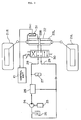
- FIG. 1 a schematic diagram of a braking force control unit used in a vehicle dynamic characteristic control apparatus embodying the invention.
- the invention will be described in connection with an automotive vehicle supported on a pair of front road wheels associated with respective front wheel cylinders 1FL and 1FR situated in front wheel brakes for application of brakes to the respective front road wheels and a pair of rear road wheels associated with respective rear wheel cylinders 1RL and 1RR situated in rear wheel brakes for application of brakes to the respective rear road wheels.
- An actuator generally designated by the numeral 2, operates the wheel cylinders 1FL, 1FR, 1RF and 1RR for applying controlled braking forces to the respective road wheels.
- the numeral 4 designates a brake pedal which actuates the pistons in a tandem master cylinder 5 and forces fluid through first and second conduits 5a and 5b to the actuator 2.
- the actuator 2 includes solenoid valves 3FL, 3FR and 3R.
- the solenoid valve 3FL has three ports A, B and P.
- the port P is connected to the first conduit 5a
- the port A is connected to the wheel cylinder 1FL
- the port B is connected to the first conduit 5a through a motor driven pump 7F.
- a reservoir 9F is connected to the conduit connected between the port B and the pump 7F.
- An accumulator 8F is connected to the conduit connected between the pump 7F and the port P for charging up the fluid flow through the conduit.
- the solenoid valve 3FL operates on a command current signal fed thereto from a control unit 16 to occupy one of three positions. The first position, illustrated in Fig.
- the first position is encountered to interrupt the communication between the ports P and A so as to retain the fluid pressure in the wheel cylinder 1FL at a constant value.
- the third position is encountered to provide communication between the ports A and B so as to reduce the fluid pressure in the wheel cylinder 1FL.
- the solenoid valve 3FR has three ports A, B and P.
- the port P is connected to the first conduit 5a and also to the port P of the solenoid valve 3FL
- the port A is connected to the wheel cylinder 1FR
- the port B is connected to the port B of the solenoid valve 3FL.
- the solenoid valve 3FR operates on a command current signal fed thereto from the control unit 16 to occupy one of three positions.
- the first position, illustrated in Fig. 1 is occupied to provide communication between the ports P and A so as to increase the fluid pressure introduced into the wheel cylinder 1FR.
- the second position is encountered to interrupt the communication between the ports P and A so as to retain the fluid pressure in the wheel cylinder 1FR at a constant value.
- the third position is encountered to provide communication between the ports A and B so as to reduce the fluid pressure in the wheel cylinder 1FR.
- the solenoid valve 3R has three ports A, B and P.
- the port P is connected to the second conduit 5b
- the port A is connected to the wheel cylinders 1RL and 1RR
- the port B is connected to the second conduit 5b through a motor driven pump 7R.
- a reservoir 9R is connected to the conduit connected between the port B and the pump 7R.
- An accumulator 8R is connected to the conduit connected between the pump 7R and the port P for charging up the fluid flow through the conduit.
- the solenoid valve 3R operates on a command current signal fed thereto from the control unit 16 to occupy one of three positions. The first position, illustrated in Fig. 1, is occupied to provide communication between the ports P and A so as to increase the fluid pressure introduced to the wheel cylinders 1RL and 1RR.
- the second position is encountered to interrupt the communication between the ports P and A so as to retain the fluid pressure in the wheel cylinders 1RL and 1RR at a constant value.
- the third position is encountered to provide communication between the ports A and B so as to reduce the fluid pressure in the wheel cylinders 1RL and 1RR.
- Each of the command current signals to the respective solenoid valves 3FL, 3FR and 3R has three levels repetitively determined from calculations performed by the control unit 16. These calculations are made based upon various conditions of the automotive vehicle that are sensed during its operation. These sensed conditions include steering angle ⁇ , vehicle speed Vx, brake pedal position, master cylinder pressure P MC , fluid pressures P FL and P FR supplied to the respective wheel cylinders 1FL and 1FR, and fluid pressure PR supplied to the wheel cylinders 1RL and 1RR.
- a steering angle sensor 11, a vehicle speed sensor 12, a brake switch 13, and fluid pressure sensors 14MC, 14FL, 14FR and 14R are connected to the control unit 16.
- the steering angle sensor 11 is provided to sense the degree ⁇ of rotation of a steering wheel 10 with respect to its neutral position and it produces an electric signal indicative of the sensed steering angle ⁇ .
- the steering angle indication signal has a sign indicating the direction in which the steering wheel turns. In the illustrated case, the steering angle indication signal has a positive sign when the steering wheel 10 turns to the left with respect to its neutral position and a negative sign with the steering wheel 10 turns to the right with respect to its neutral position.
- the vehicle speed sensor 12 is provided to sense the vehicle longitudinal speed Vx and it produces an electric signal indicative of the sensed vehicle speed Vx.
- the brake switch 13 is associated with the brake pedal 4 to close to supply current from the engine battery to the control unit 16 in response to the application of foot braking to the vehicle (when the brake pedal 4 is depressed).
- the master cylinder pressure sensor 14MC is shown as positioned in the first conduit 5a to sense the fluid pressure P MC and it produces an electric signal indicative of the sensed pressure P MC of the fluid discharged from the master cylinder 5.
- the fluid pressure sensors 14FL and 14FR are positioned to sense the fluid pressures P FL and P FR introduced into the respective wheel cylinders 1FL and 1FR.
- the fluid pressure sensors 14FL and 14FR produce electric signals indicative of the sensed fluid pressures P FL and P FR to the control unit 16.
- the fluid pressure sensor 14R is positioned to sense the fluid pressure PF introduced into the wheel cylinders 1RL and 1RR.
- the fluid pressure sensors 14R produces an electric signal indicative of the sensed fluid pressure P R to the control unit 16.
- the control unit 16 may employ a digital computer including an input interface, an output interface, a central processing unit, and a memory.
- the control processing unit communicates with the rest of the computer va data bus.
- the memory contains programs for operating the central processing unit and further contains appropriate data (vehicle model) used in calculating appropriate command signal values.
- the vehicle model may be derived from equations of motions of a vehicle similar to the vehicle to be controlled.
- the calculated command signal valves are transferred by the central processing unit to the output interface which converts them into analog form for application to respective floating type constant current circuits.
- the constant current circuits set the solenoid valves 3FL, 3FR and 3R and the pumps 7F and 7R according to the calculated values for them to perform anti-skid control and braking force differential control.
- FIG. 2 there is shown a rear-wheel steering control unit used in the vehicle dynamic characteristic control apparatus of the invention.
- the rear wheels 21L and 21R are associated with an auxiliary steering actuator 22 of the spring center type having two pressure chambers 22L and 22R for turning the rear wheels 21L and 21R in response to the fluid pressure acting in the first or second pressure chamber 22L or 22R.
- the auxiliary steering actuator 22 turns the rear wheels 21L and 21R in a counter-clockwise direction at an angle proportional to the fluid pressure introduced into the first pressure chamber 22L with respect to the vehicle longitudinal axis and it turns the rear wheels 21L and 21R in the clockwise direction at an angle proportional to the fluid pressure introduced into the second pressure chamber 22R with respect to the vehicle longitudinal axis.
- a pump 24, which is driven by the engine 23, supplies fluid from a reservoir 25 through an unloading valve 26 to cause an accumulator 27 to be charged up the fluid flow through a conduit 28.
- the rear-wheel steering control unit includes a control valve 30 operable on a command current signal fed thereto from the control unit 16 to occupy one of three positions.
- the first position is occupied when the command current signal is a first level and the control valve 30 provides communication of the first chamber 22L of the auxiliary steering actuator 22 with the conduit 28 and communication of the second chamber 22R of the auxiliary steering actuator 22 with a drain conduit 29 which is connected through a check valve to the reservoir 25.
- the rear wheels 21L and 21R turn in the counter-clockwise direction.
- the second position, illustrated in Fig. 2 is occupied when the command current signal is a level of zero and the control valve 30 interrupts the communication of the auxiliary steering actuator 22 with the conduits 28 and 29 to retain the existing rear-wheel steering angle.
- the third position is encountered when the command current signal is a second level and the control valve 30 provides communication of the first pressure chamber 22L with the drain conduit 29 and communication of the second pressure chamber 22R with the conduit 28.
- the rear wheels 21L and 21R turn in the clockwise direction.
- a rear-wheel steering angle sensor 31 is provided to sense the steering angle of the rear wheels 21L and 21R.
- the rear-wheel steering angle sensor 31 provides a feedback signal to the control unit 16 to ensure that the rear-wheel steering angle is correct to maintain a target value calculated by the control unit 16.
- cornering forces Cf and Cr are given as where ⁇ (t) is the steering angle, N is the steering gear ratio, Kr is the front-wheel cornering power, Kr is the rear-wheel cornering power, and ⁇ r(t) is the rear-wheel steering angle.
- ⁇ Bf ( t ) B FL ( t ) - B FR ( t ) (7)
- a11 -2( Kf ⁇ Lf + Kr ⁇ Lr )/( Iz ⁇ Vx )
- a12 -2( Kf ⁇ Lf - Kr ⁇ Lr )/( Iz ⁇ Vx ) (9)
- a21 -2( Kf ⁇ Lf - Kr ⁇ Lr )/( M ⁇ Vx )- Vx (10)
- a22 -2( Kf+Kr )/( M ⁇ Vx ) (11)
- bf1 2 ⁇ Kf ⁇ Lf /( Iz ⁇ N ) (12)
- Equation (17) and (18) are the transfer functions taken in the form of (an equation of the first degree)/(an equation of the second degree). It is apparent from Equations (17) and (18) that the tendency of the produced yaw rate ⁇ 1(t) and the lateral speed Vy1(t) to oscillate with respect to the steering angle ⁇ (t) increases so as to degrade the vehicle steering performance as the vehicle speed Vx increases. It has been proposed to control the rear-wheel steering angle in such a manner that the produced yaw rate agrees well with a target yaw rate ⁇ r(t).
- the target yaw rate ⁇ r(t) has a first order lag without any over- and under-shoot with respect to the steering angle ⁇ (t) and its steady value is equal to that for normal vehicles in the absence of vehicle braking
- the differentiated value of the produced yaw rate will be equal to the differentiated value of the target yaw rate.
- Fig. 4 shows a friction circle used to provide the concept of the relationship of the front wheel cornering force Cf with the braking and driving forces.
- the maximum cornering force value Cfmax upon application of a braking force Bf is given by
- the cornering power Kf of the front wheels upon application of the braking force Bf is given by
- the front wheel cornering power Kf is the average value of the cornering powers of the left and right front road wheels
- the front wheel cornering power Kf upon application of braking forces B FL and B FR to the left and right front wheels, respectively is given by
- the cornering power Kf of the rear wheels upon application of the braking force Br is given by where Fo' is the maximum possible frictional force produced by the rear wheels and Kro is the rear wheel cornering power in the absence of vehicle braking.
- the front- and rear-wheel cornering powers Kf and Kr produced during vehicle braking are calculated from Equations (29) and (30).
- the calculated cornering powers Kf and Kr are substituted into Equations (8) to (15) to calculate various coefficients.
- the calculated coefficients are used to calculate a target value for rear-wheel steering angle from Equation (25).
- the control unit 16 controls the rear-wheel steering control unit of Fig. 2 to bring the rear-wheel steering angle to the target value calculated from Equation (25).
- the produced yaw rate agrees well with the target yaw rate during vehicle braking.
- the rear-wheel steering angle control can bring the yaw rate into coincidence with its target value, there is a deviation of the vehicle lateral speed from its target value, as shown in Fig. 6.
- the deviation of the vehicle lateral speed from its target value is eliminated, as shown in Fig. 5, by controlling the braking force control unit of Fig. 1 to provide a difference between the braking force applied to the left-front wheel and the braking force applied to the right-front wheel in the presence of vehicle braking.
- the braking force difference is controlled to bring the vehicle lateral speed Vy to a target value Vyr(t) equal to the vehicle lateral speed provided when the rear-wheel steering angle is controlled to its target value calculated from Equation (25) in the absence of vehicle braking.
- the steady and transient characteristics of the vehicle lateral speed in the presence of vehicle braking are the same as those in the absence of the vehicle braking.
- Vyr(t) The target lateral speed Vyr(t) is calculated from Equation (31). This equation may be derived from Equation (24).
- V ⁇ yr ( t ) a21' ⁇ r ( t ) + a22' ⁇ Vyr ( t ) + Bf2' ⁇ ⁇ ( t ) + br2' ⁇ ⁇ r' ( t ) (31)
- a21', a22', bf2' and br2' are parameters a21, a22, bf2 and br2 calculated from Equations (10), (11), (13) and (15) using cornering powers Kfo and Kro produced in the absence of vehicle braking and ⁇ r'(t) is the rear-wheel steering angle calculated from Equation (32).
- Equation (25) This equation may be derived from Equation (25).
- a11', a12' , bf1' and br1' are the parameters a11, a12, bf1 and br1 calculated from Equations (8), (9), (12) and (14) using cornering powers Kfo and Kro produced in the absence of vehicle braking.
- the differentiated value is equal to and the differentiated value V ⁇ y(t) is equal to V ⁇ yr(t).
- kp 2 ⁇ p ⁇ Ap ⁇ rp/R
- ⁇ p the coefficient of friction between the brake pad and the disc rotor
- Ap the area of the wheel cylinder
- rp the effective radius of the disc rotor
- R the radius of the tyre.
- the target wheel cylinder pressures P FL (t) and P FR (t) are calculated based upon the target pressure difference ⁇ P(t) calculated from Equation (38) and the master cylinder pressure P MC (t). These calculations are made as follows:
- Fig. 7 is a flow diagram illustrating the programming of the digital computer as it is used to calculate target values P* FL and P* FR for the fluid pressures to be supplied to the wheel cylinders 1FL and 1FR.
- the computer program is entered at the point 102 at uniform intervals of time ⁇ T.
- the vehicle speed Vx, the steering angle ⁇ , the master cylinder pressure P MC and the wheel cylinder pressures P FL , P FR and P RR are read into the computer memory.
- the front- and rear-wheel cornering powers Kf and Kr produced in the presence of vehicle braking are calculated from Equations (29) and (30).
- the coefficients a11, a12, a21, a22, bf1, bf2, br1 and br2 are calculated for the presence of vehicle braking.
- the coefficients bf1, bf2, br1 and br2 are calculated from Equations (12) to (15).
- a'11V -2 ⁇ (Kfo ⁇ Lf2 + Kro ⁇ Lr2)/Iz
- a'12V -2 ⁇ (Kfo ⁇ Lf - Kro ⁇ Lr)/Iz
- a'21V -2 ⁇ (Kfo ⁇ Lf - Kro ⁇ Lr)/M
- Kfo + Kro the front- and rear-wheel cornering powers produced in the absence of vehicle braking.
- the coefficients a'11, a'12, a'21, a'22, b'f1, b'f2, b'r1 and b'r2 are calculated for the absence of vehicle braking.
- the steady yaw rate gain Ho is calculated, from Equation (20), based upon the vehicle speed Vx, the stability factor A calculated from Equation (21), the wheel base L and the steering gear ratio N.
- the calculated steady yaw rate gain Ho is used to calculate the differentiated value of the target yaw rate from Equation (22)
- the present target yaw rate ⁇ r(n) is calculated, from Equation (39), based upon the new differentiated yaw rate value calculated in the present cycle of execution of this program and the last differentiated yaw rate value calculated in the last cycle of execution of the program.
- the calculated target yaw rate value ⁇ r(n) is used to update the last target yaw rate value stored in the computer memory.
- ⁇ T is the time interval between successive entries of this program.
- the lateral acceleration V ⁇ yr(n) is calculated, from Equation (31) based upon the coefficients a'21, a'22, b'f2 and b'r2 calculated at the point 114, the last target yaw rate ⁇ r(n-1), the last lateral speed Vyr(n-1) and the target rear-wheel steering angle ⁇ 'r used in the absence of vehicle braking.
- the calculated lateral speed Vyr(n) is used along with the last lateral acceleration value V ⁇ yr(n-1) to calculate the present lateral speed Vyr(n) from Equation (40).
- the calculated lateral speed value Vyr(n) is used to update the last lateral speed value stored in the computer memory.
- Vyr ( n ) Vyr ( n -1) + V ⁇ yr ( n ) ⁇ T (40)
- the calculated lateral speed value Vyr(n) is used to calculate a target rear-wheel steering angle ⁇ 'r from Equation (41).
- the control unit 16 control the control valve 30 to bring the rear-wheel steering angle to its target value ⁇ 'r so as to realize the target yaw rate in the absence of vehicle braking.
- the central processing unit calculates a target rear-wheel steering angle ⁇ r(n) used in the presence of vehicle braking from Equation (36) and a difference ⁇ Bf(n) between the braking forces applied to the left and right front wheels from Equation (35).
- the calculated braking force difference value ⁇ Bf is used, along with the coefficient kp calculated previously from Equation (37), to calculate a target pressure difference value ⁇ P from Equation (38).
- the program proceeds from the point 122 to the point 126 where the master cylinder pressure P MC is set for the target cylinder pressure P* FR to be supplied to the wheel cylinder 1FR and a greater one of "0" and the difference (P MC - ⁇ P) between the master cylinder pressure P MC and the target pressure difference ⁇ P for the target cylinder pressure P* FL to be supplied to the wheel cylinder 1FL. Following this, the program proceeds to the end point 128.
- Fig. 8 is a flow diagram illustrating the programming of the digital computer as it is used to control the fluid pressure introduced to the wheel cylinder 1FL.
- the computer program is entered at the point 202 at uniform intervals of time ⁇ .
- a determination is made as to whether or not the brake switch 13 is off. If the answer to this question is "yes", then it means the absence of vehicle braking and the program proceeds to the point 206 where a first variable Tp is set at 1 and then to the point 208 where a second variable m is set at 1.
- the first variable Tp indicates the time interval during which the control signal to be described later is retained
- the second variable m indicates the time intervals at which an error between the actual cylinder pressure P FL and the target cylinder pressure P* FL is monitored.
- the brake switch 13 If the brake switch 13 is on, then it means that brakes are applied to the vehicle and the program proceeds from the point 204 to another determination step at the point 210. This determination is as to whether or not the target cylinder pressure P* FL calculated in the program of Fig. 7 is equal to the master cylinder pressure P MC . If the answer to this question is "yes”, then the program proceeds to the point 206. Otherwise, the program proceeds to the point 212.
- the second variable m is set at a predetermined value mo. Upon completion of this setting, the program proceeds to the point 220.
- the new value (Tp - 1) of the first variable is used to update the last first variable value stored in the computer memory. Following this, the program proceeds to the point 232.
- the program proceeds from the point 220 to the point 226 where a command is produced to output a control signal CSFL having a second value VS2 causing the constant current circuit to move the solenoid valve 3FL to the second position retaining the fluid pressure in the wheel cylinder 1FL. Following this, the program proceeds to the point 232.
- the program proceeds from the point 220 to the point 228 where a command is produced to output a control signal CSFL having a third value VS3 causing the constant current circuit to move the solenoid valve 3FL to the third position decreasing the fluid pressure in the wheel cylinder 1FL and then to the point 230 where 1 is added to the first variable Tp.
- the new value (Tp + 1) is used to update the last value of the first variable stored in the computer memory. Following this, the program proceeds to the point 232.
- a similar program is executed separately at uniform intervals of time ⁇ T for controlling the fluid pressure introduced to the wheel cylinder 1FR.
- the brake switch 13 When the vehicle is traveling in the absence of vehicle braking, the brake switch 13 is off and the first variable Tp is set at 1.
- the control signal CSFL has a first value VS1 causing the solenoid valve 3FL to be held in the first or normal position providing communication between the master cylinder 5 and the wheel cylinder 1FL
- the control signal CSFR has a first value VS1 causing the solenoid valve 3FR to be held in the first or normal position providing communication between the master cylinder 5 and the wheel cylinder 1FR. Since the master cylinder pressure discharged from the master cylinder 5 is zero in the absence of vehicle braking, the pressures in the wheel cylinders 1FL and 1FR are zero so that no braking force is produced.
- control signal CSFL has a first value VS1 causing the solenoid valve 3FL to be held in the first or normal position providing communication between the master cylinder 5 and the wheel cylinder 1FL
- control signal CSFR has a first value VS1 causing the solenoid valve 3FR to be held in the first or normal position providing communication between the master cylinder 5 and the wheel cylinder 1FR.
- the target cylinder pressure P* FL (or P* FR ) will be set at a value equal to the master cylinder pressure P MC minus the target pressure difference ⁇ P, as described in connection with the program of Fig. 7. Since the second variable m is set at zero at the point 232 during the last cycle of execution of the program of Fig. 8, an error Perr between the actual cylinder pressure P FL (or P FR ) sensed by the pressure sensor 14FL (or 14FR) and the target cylinder pressure P* FL (or P* FR ) is calculated at the point 214 in the program of Fig.
- the first variable Tp is set at a value INT(Perr/Po) at the point 216 in the program of Fig. 8
- the second variable m is set at a redetermined value mo at the point 218 in the program of Fig. 8.
- the control signal CSFL has a first value VS1 causing the solenoid valve 3FL to be held in the first or normal position providing communication between the master cylinder 5 and the wheel cylinder 1FL
- the control signal CSFR has a first value VS1 causing the solenoid valve 3FR to be held in the first or normal position providing communication between the master cylinder 5 and the wheel cylinder 1FR.
- This pressure increasing mode continues until the first variable Tp is reduced to zero at the point 224 in the program of Fig. 8.
- the control signal CSFL (or CSFR) has a second value VS2 causing the solenoid valve 3FL (or 3FR) to move to the second position interrupting communication between the master cylinder 5 and the wheel cylinder 1FL (or 1FR) so as to retain the fluid pressure P FL (or P FR ) in the wheel cylinder 1FL (or 1FR) at a constant value.
- This pressure retaining mode continues until the second variable m is reduced to zero at the point 234 in the program of Fig. 8.
- an error Perr between the actual cylinder pressure P FL (or P FR ) sensed by the pressure sensor 14FL (or 14FR) and the target cylinder pressure P* FL or (P* FR ) is calculated at the point 214 in the program of Fig. 8, and the first variable Tp is set at a value INT(Perr/Po) at the point 216 in the program of Fig. 8, and the second variable m is set at a predetermined value mo at the point 218 in the program of Fig. 8.
- the first variable Tp is set at zero and thus the pressure retaining mode is selected so that the cylinder pressure P FL (or P FR ) is retained at the target cylinder pressure P* FL (or P* FR ).
- the cylinder pressure P FL (or P FR ) in the wheel cylinder 1FL (or 1FR) is greater than the target cylinder pressure P* FL (or P* FR )
- the error Perr is negative and thus the first variable Tp is negative.
- control signal CSFL (or CSFR) has a third value VS3 causing the solenoid valve 3FL (or 3FR) to move to the third position providing communication of the wheel cylinder 1FL (or 1FR) to the master cylinder 5 through the pump 7F so as to reduce the cylinder pressure P FL (or P FR ) in the wheel cylinder 1FL (or 1FR).
- This pressure reduction mode continues until the first variable Tp is reduced to zero.
- the cylinder pressures P FL and P FR in the wheel cylinders 1FL and 1FR can be adjusted to the target cylinder pressures P* FL and P* FR , respectively.
- the braking force control is used together with the rear-wheel steering control to equalize the steady and transient characteristics of parameters in terms of vehicle yaw rate and vehicle lateral speed in the presence of vehicle braking to those obtained in the absence of vehicle braking, as shown in Fig. 5. Cornering power changes are taken into account in controlling the rear-wheel steering angle in the presence of vehicle braking so that the steady and transient characteristic of a first vehicle dynamic parameter (in the illustrated vehicle case yaw rate) in the presence of vehicle braking are the same as those in the absence of vehicle braking.
- a difference between the braking force applied to the right-front wheel and the braking force applied to the left-front wheel is provided in the presence of vehicle braking to realize the steady and transient characteristics of a second vehicle dynamic parameter (in the illustrated case vehicle lateral speed) which are obtained by the rear-wheel steering control in the absence of vehicle braking.
- a second vehicle dynamic parameter in the illustrated case vehicle lateral speed
- front- and/or rear- wheel steering control may be utilized to control the yaw rate.
- vehicle dynamic characteristic control apparatus of the invention may be arranged to provide a difference between the braking force applied to the left-rear wheel and the braking force applied to the right-rear wheel to control the vehicle lateral speed.
- the vehicle longitudinal acceleration may be used, along with the wheel cylinder pressures, to calculate the cornering powers in the presence of vehicle braking.
Landscapes
- Engineering & Computer Science (AREA)
- Transportation (AREA)
- Mechanical Engineering (AREA)
- Chemical & Material Sciences (AREA)
- Combustion & Propulsion (AREA)
- Physics & Mathematics (AREA)
- Mathematical Physics (AREA)
- Theoretical Computer Science (AREA)
- Regulating Braking Force (AREA)
- Steering-Linkage Mechanisms And Four-Wheel Steering (AREA)
- Steering Control In Accordance With Driving Conditions (AREA)
Applications Claiming Priority (2)
| Application Number | Priority Date | Filing Date | Title |
|---|---|---|---|
| JP2224243A JP2623940B2 (ja) | 1990-08-28 | 1990-08-28 | 車両の挙動制御装置 |
| JP224243/90 | 1990-08-28 |
Publications (3)
| Publication Number | Publication Date |
|---|---|
| EP0473112A2 true EP0473112A2 (de) | 1992-03-04 |
| EP0473112A3 EP0473112A3 (en) | 1992-07-08 |
| EP0473112B1 EP0473112B1 (de) | 1995-03-29 |
Family
ID=16810736
Family Applications (1)
| Application Number | Title | Priority Date | Filing Date |
|---|---|---|---|
| EP91114357A Expired - Lifetime EP0473112B1 (de) | 1990-08-28 | 1991-08-27 | Verfahren zur Steuerung der dynamischen Eigenschaften eines Kraftfahrzeuges |
Country Status (4)
| Country | Link |
|---|---|
| US (1) | US5341296A (de) |
| EP (1) | EP0473112B1 (de) |
| JP (1) | JP2623940B2 (de) |
| DE (1) | DE69108480T2 (de) |
Cited By (9)
| Publication number | Priority date | Publication date | Assignee | Title |
|---|---|---|---|---|
| FR2695367A1 (fr) * | 1992-09-10 | 1994-03-11 | Bosch Gmbh Robert | Système de régulation de la dynamique du freinage d'un véhicule. |
| WO1999001320A1 (de) * | 1997-06-30 | 1999-01-14 | Robert Bosch Gmbh | Verfahren und vorrichtung zur regelung von die fahrzeugbewegung repräsentierenden bewegungsgrössen |
| EP0881114A3 (de) * | 1997-05-31 | 1999-05-12 | Rover Group Limited | Fahrzeuglenkkontrolle |
| WO2000071404A1 (de) * | 1999-05-20 | 2000-11-30 | Zf Friedrichshafen Ag | Lenkvorrichtung und lenkverfahren |
| EP1231127A3 (de) * | 2001-02-13 | 2004-01-02 | Koyo Seiko Co., Ltd. | Lenkvorrichtung eines Kraftfahrzeugs |
| WO2004020262A1 (de) * | 2002-08-09 | 2004-03-11 | Bayerische Motoren Werke Aktiengesellschaft | Verfahren zum führen eines mehrspurigen fahrzeugs auf einer kurvenbahn |
| WO2009124614A1 (de) * | 2008-04-09 | 2009-10-15 | Daimler Ag | Verfahren zum beeinflussen der querdynamik eines fahrzeugs |
| CN108327783A (zh) * | 2018-02-07 | 2018-07-27 | 北京理工大学 | 一种自动转向控制装置、自动转向控制系统及控制方法 |
| US20230044869A1 (en) * | 2021-07-22 | 2023-02-09 | GM Global Technology Operations LLC | Vehicle actuation commands to affect transient handling |
Families Citing this family (37)
| Publication number | Priority date | Publication date | Assignee | Title |
|---|---|---|---|---|
| DE4226746C1 (de) * | 1992-08-13 | 1993-10-07 | Daimler Benz Ag | Verfahren zur Bestimmung eines fahrsituationsabhängigen Lenkwinkels |
| DE4333961A1 (de) * | 1992-10-05 | 1994-04-07 | Mazda Motor | Vorrichtung zur Begrenzung des Antriebsrad-Differentials für Fahrzeuge |
| JPH07323859A (ja) * | 1994-06-01 | 1995-12-12 | Nissan Motor Co Ltd | 車両運動制御装置 |
| US5471386A (en) * | 1994-10-03 | 1995-11-28 | Ford Motor Company | Vehicle traction controller with torque and slip control |
| US5710705A (en) | 1994-11-25 | 1998-01-20 | Itt Automotive Europe Gmbh | Method for determining an additional yawing moment based on side slip angle velocity |
| US5742507A (en) | 1994-11-25 | 1998-04-21 | Itt Automotive Europe Gmbh | Driving stability control circuit with speed-dependent change of the vehicle model |
| US5701248A (en) | 1994-11-25 | 1997-12-23 | Itt Automotive Europe Gmbh | Process for controlling the driving stability with the king pin inclination difference as the controlled variable |
| US5711024A (en) | 1994-11-25 | 1998-01-20 | Itt Automotive Europe Gmbh | System for controlling yaw moment based on an estimated coefficient of friction |
| US5732379A (en) | 1994-11-25 | 1998-03-24 | Itt Automotive Europe Gmbh | Brake system for a motor vehicle with yaw moment control |
| US5732377A (en) | 1994-11-25 | 1998-03-24 | Itt Automotive Europe Gmbh | Process for controlling driving stability with a yaw rate sensor equipped with two lateral acceleration meters |
| US5732378A (en) | 1994-11-25 | 1998-03-24 | Itt Automotive Europe Gmbh | Method for determining a wheel brake pressure |
| DE19515050A1 (de) | 1994-11-25 | 1996-05-30 | Teves Gmbh Alfred | Verfahren zur Fahrstabilitätsregelschaltung mit Steuerung über Druckgradienten |
| US5694321A (en) | 1994-11-25 | 1997-12-02 | Itt Automotive Europe Gmbh | System for integrated driving stability control |
| US5774821A (en) | 1994-11-25 | 1998-06-30 | Itt Automotive Europe Gmbh | System for driving stability control |
| US5710704A (en) | 1994-11-25 | 1998-01-20 | Itt Automotive Europe Gmbh | System for driving stability control during travel through a curve |
| JP3067564B2 (ja) * | 1995-01-12 | 2000-07-17 | トヨタ自動車株式会社 | 車両旋回制御装置 |
| US5682316A (en) * | 1995-06-05 | 1997-10-28 | Ford Motor Company | Vehicle traction controller with engine and brake control |
| US5915800A (en) * | 1995-06-19 | 1999-06-29 | Fuji Jukogyo Kabushiki Kaisha | System for controlling braking of an automotive vehicle |
| JP3463415B2 (ja) * | 1995-06-22 | 2003-11-05 | 日産自動車株式会社 | 車両のヨーイング挙動制御装置 |
| JP3257351B2 (ja) * | 1995-07-07 | 2002-02-18 | 三菱自動車工業株式会社 | 車両の旋回制御装置 |
| JP3336835B2 (ja) * | 1995-10-19 | 2002-10-21 | トヨタ自動車株式会社 | 車輌の挙動制御装置 |
| FR2743162B1 (fr) * | 1995-12-27 | 1998-05-07 | Dassault Electronique | Dispositif de commande pour la securisation d'un vehicule rapide, notamment guide par un operateur embarque ou non dans ledit vehicule |
| JPH09226559A (ja) * | 1996-02-23 | 1997-09-02 | Toyota Motor Corp | 制駆動力制御用基準車輪速度演算装置 |
| JP3360528B2 (ja) * | 1996-06-19 | 2002-12-24 | 日産自動車株式会社 | 車両運動制御装置 |
| JP3348619B2 (ja) * | 1997-03-04 | 2002-11-20 | トヨタ自動車株式会社 | 車輌の挙動制御装置 |
| DE19851978A1 (de) * | 1998-11-11 | 2000-05-25 | Daimler Chrysler Ag | Verfahren zur Regelung der Querdynamik eines Fahrzeuges mit Vorderachs-Lenkung |
| US6195606B1 (en) * | 1998-12-07 | 2001-02-27 | General Motors Corporation | Vehicle active brake control with bank angle compensation |
| JP3650714B2 (ja) * | 2000-02-08 | 2005-05-25 | 光洋精工株式会社 | 車両用操舵装置 |
| JP4062848B2 (ja) | 2000-02-23 | 2008-03-19 | アイシン・エィ・ダブリュ株式会社 | 自動変速機の制御装置 |
| DE10039782A1 (de) * | 2000-08-16 | 2002-02-28 | Daimler Chrysler Ag | Verfahren zur Regelung der Gier-und Querdynamik bei einem Straßenfahrzeug |
| JP3689046B2 (ja) * | 2002-01-25 | 2005-08-31 | カヤバ工業株式会社 | パワーステアリング装置 |
| DE102005037479B4 (de) * | 2005-08-09 | 2017-10-26 | Bayerische Motoren Werke Aktiengesellschaft | Fahrdynamik-Steuerungssystem für ein zweispuriges Kraftfahrzeug |
| WO2007129750A1 (ja) * | 2006-05-10 | 2007-11-15 | Toyota Jidosha Kabushiki Kaisha | 車両転舵制御装置 |
| US20080105484A1 (en) * | 2006-11-03 | 2008-05-08 | Sauer-Danfoss Inc. | Electronic redundant steer by wire valve |
| JP2008238934A (ja) * | 2007-03-27 | 2008-10-09 | Mitsubishi Motors Corp | パワーステアリング装置 |
| CN102958734B (zh) * | 2010-07-09 | 2015-07-29 | 日产自动车株式会社 | 车辆的左右轮驱动分配控制装置 |
| DE102015008587A1 (de) * | 2015-07-02 | 2017-01-05 | Audi Ag | Kraftfahrzeug für ein pilotiertes Fahren mit einem Vorderachslenksystem und einem Hinterachslenksystem |
Family Cites Families (17)
| Publication number | Priority date | Publication date | Assignee | Title |
|---|---|---|---|---|
| JPS6127763A (ja) * | 1984-07-17 | 1986-02-07 | Nissan Motor Co Ltd | 車両の運動目標値設定装置 |
| US4679809A (en) * | 1984-09-10 | 1987-07-14 | Nissan Motor Co., Ltd. | Steering control system for wheeled vehicle |
| JPS61113562A (ja) * | 1984-11-06 | 1986-05-31 | Nissan Motor Co Ltd | 車両用舵角制御装置 |
| US4706771A (en) * | 1985-01-31 | 1987-11-17 | Nissan Motor Co., Ltd. | Vehicle steering control system using desired vehicle model |
| JPS62137276A (ja) * | 1985-12-09 | 1987-06-20 | Nissan Motor Co Ltd | 車両用操舵系制御装置 |
| US4761022A (en) * | 1986-03-08 | 1988-08-02 | Toyota Jidosha Kabushiki Kaisha | Suspension controller for improved turning |
| DE3616907A1 (de) * | 1986-05-20 | 1987-11-26 | Hans Prof Dr Ing Marko | Einrichtung zur regelung der drehgeschwindigkeit eines kraftfahrzeuges um die hochachse |
| US4779696A (en) * | 1986-07-24 | 1988-10-25 | Mazda Motor Corporation | Vehicle slip control apparatus |
| JPH0725320B2 (ja) * | 1986-10-13 | 1995-03-22 | 日産自動車株式会社 | 車両用実舵角制御装置 |
| DE3826982C2 (de) * | 1987-08-10 | 2000-11-30 | Denso Corp | Hilfslenksystem verbunden mit einem Antiblockiersteuerungssystem zur Verwendung in Kraftfahrzeugen |
| JP2804760B2 (ja) * | 1988-01-22 | 1998-09-30 | 雅彦 三成 | 自動車の操縦制御装置 |
| DE3825639C2 (de) * | 1988-07-28 | 1995-10-12 | Sepp Gunther | Einrichtung zum Stabilisieren von Kraftfahrzeugen bei Kurvenfahrt |
| US5141069A (en) * | 1988-09-13 | 1992-08-25 | Aisin Seiki Kabushiki Kaisha | Steering mechanism with toe-in control |
| JP2641743B2 (ja) * | 1988-09-22 | 1997-08-20 | 本田技研工業株式会社 | 四輪操舵車の後輪制御方法 |
| US5079708A (en) * | 1989-03-24 | 1992-01-07 | Brown Jack L | Road vehicle cornering assistance mechanism |
| US4998593A (en) * | 1989-03-31 | 1991-03-12 | Aisin Seiki Kabushiki Kaisha | Steering and brake controlling system |
| JP2514248B2 (ja) * | 1989-05-16 | 1996-07-10 | 日産自動車株式会社 | 車両動特性制御装置 |
-
1990
- 1990-08-28 JP JP2224243A patent/JP2623940B2/ja not_active Expired - Fee Related
-
1991
- 1991-08-27 EP EP91114357A patent/EP0473112B1/de not_active Expired - Lifetime
- 1991-08-27 DE DE69108480T patent/DE69108480T2/de not_active Expired - Fee Related
- 1991-08-27 US US07/750,563 patent/US5341296A/en not_active Expired - Fee Related
Cited By (16)
| Publication number | Priority date | Publication date | Assignee | Title |
|---|---|---|---|---|
| FR2695367A1 (fr) * | 1992-09-10 | 1994-03-11 | Bosch Gmbh Robert | Système de régulation de la dynamique du freinage d'un véhicule. |
| EP0881114A3 (de) * | 1997-05-31 | 1999-05-12 | Rover Group Limited | Fahrzeuglenkkontrolle |
| US6176336B1 (en) | 1997-05-31 | 2001-01-23 | Rover Group Limited | Vehicle steering control |
| WO1999001320A1 (de) * | 1997-06-30 | 1999-01-14 | Robert Bosch Gmbh | Verfahren und vorrichtung zur regelung von die fahrzeugbewegung repräsentierenden bewegungsgrössen |
| US6226581B1 (en) | 1997-06-30 | 2001-05-01 | Robert Bosch Gmbh | Method and device for controlling motion parameters representing the movement of a motor vehicle motion quantity |
| WO2000071404A1 (de) * | 1999-05-20 | 2000-11-30 | Zf Friedrichshafen Ag | Lenkvorrichtung und lenkverfahren |
| US6611745B1 (en) | 1999-05-20 | 2003-08-26 | Zf Friedrichshafen Ag | Steering system and steering method |
| EP1231127A3 (de) * | 2001-02-13 | 2004-01-02 | Koyo Seiko Co., Ltd. | Lenkvorrichtung eines Kraftfahrzeugs |
| WO2004020262A1 (de) * | 2002-08-09 | 2004-03-11 | Bayerische Motoren Werke Aktiengesellschaft | Verfahren zum führen eines mehrspurigen fahrzeugs auf einer kurvenbahn |
| US7200479B2 (en) | 2002-08-09 | 2007-04-03 | Bayerische Motoren Werke Aktiengesellschaft | Method for guiding a multitrack vehicle on a curved path |
| WO2009124614A1 (de) * | 2008-04-09 | 2009-10-15 | Daimler Ag | Verfahren zum beeinflussen der querdynamik eines fahrzeugs |
| US8554409B2 (en) | 2008-04-09 | 2013-10-08 | Daimler Ag | Method for influencing the transverse dynamics of a vehicle |
| CN108327783A (zh) * | 2018-02-07 | 2018-07-27 | 北京理工大学 | 一种自动转向控制装置、自动转向控制系统及控制方法 |
| CN108327783B (zh) * | 2018-02-07 | 2019-09-17 | 北京理工大学 | 一种自动转向控制装置、自动转向控制系统及控制方法 |
| US20230044869A1 (en) * | 2021-07-22 | 2023-02-09 | GM Global Technology Operations LLC | Vehicle actuation commands to affect transient handling |
| US11724739B2 (en) * | 2021-07-22 | 2023-08-15 | GM Global Technology Operations LLC | Vehicle actuation commands to affect transient handling |
Also Published As
| Publication number | Publication date |
|---|---|
| JP2623940B2 (ja) | 1997-06-25 |
| DE69108480T2 (de) | 1995-11-09 |
| EP0473112B1 (de) | 1995-03-29 |
| US5341296A (en) | 1994-08-23 |
| DE69108480D1 (de) | 1995-05-04 |
| EP0473112A3 (en) | 1992-07-08 |
| JPH04108080A (ja) | 1992-04-09 |
Similar Documents
| Publication | Publication Date | Title |
|---|---|---|
| US5341296A (en) | Vehicle dynamic characteristic control apparatus | |
| US5428532A (en) | Vehicle dynamic characteristic control apparatus | |
| US5229944A (en) | Braking force control apparatus | |
| EP0476372B1 (de) | Einrichtung zur Kontrolle der Dynamik eines Fahrzeuges | |
| US5206808A (en) | Vehicle turning behavior control apparatus | |
| US5267783A (en) | Vehicle turning behavior control apparatus | |
| US5134352A (en) | Vehicle turning behavior control system | |
| EP0728644B1 (de) | Vorrichtung zur Lageregelung eines Fahrzeuges, bei dem Schlupfwinkel und Längskraft des Rades gesteuert sind | |
| US5305218A (en) | Vehicle handling control for wheel slip control systems | |
| EP0465958B1 (de) | System zur Regelung des Fahrverhaltens eines Fahrzeugs beim Bremsen | |
| US5344224A (en) | System and method for controlling braking force for automotive vehicle | |
| US5624164A (en) | Braking force distribution control system | |
| US6178368B1 (en) | Roll control device of vehicles with tracing of turning course | |
| US6027183A (en) | Vehicle dynamics control system | |
| EP0476373A2 (de) | Verfahren zur Steuerung dynamischer Eigenschaften eines Kraftfahrzeuges | |
| JPH10157589A (ja) | 制動力制御装置 | |
| US6003959A (en) | Vehicle dynamics control system | |
| US5855419A (en) | Process for controlling a distribution of braking force in a vehicle | |
| JP3161206B2 (ja) | 車両の旋回挙動制御装置 | |
| JPH04121439A (ja) | 車両の車輪速度制御装置 | |
| US8249790B2 (en) | Vehicle behavior control device | |
| US5329805A (en) | Vehicle body speed estimating method in anti-lock control system for vehicle | |
| JPH07223526A (ja) | 車両状態推定装置及び制動制御装置 | |
| JP2712786B2 (ja) | 制動力制御装置 | |
| JP2903784B2 (ja) | 制動力制御装置 |
Legal Events
| Date | Code | Title | Description |
|---|---|---|---|
| PUAI | Public reference made under article 153(3) epc to a published international application that has entered the european phase |
Free format text: ORIGINAL CODE: 0009012 |
|
| 17P | Request for examination filed |
Effective date: 19910827 |
|
| AK | Designated contracting states |
Kind code of ref document: A2 Designated state(s): DE GB |
|
| PUAL | Search report despatched |
Free format text: ORIGINAL CODE: 0009013 |
|
| AK | Designated contracting states |
Kind code of ref document: A3 Designated state(s): DE GB |
|
| 17Q | First examination report despatched |
Effective date: 19930810 |
|
| GRAA | (expected) grant |
Free format text: ORIGINAL CODE: 0009210 |
|
| AK | Designated contracting states |
Kind code of ref document: B1 Designated state(s): DE GB |
|
| REF | Corresponds to: |
Ref document number: 69108480 Country of ref document: DE Date of ref document: 19950504 |
|
| PLBE | No opposition filed within time limit |
Free format text: ORIGINAL CODE: 0009261 |
|
| STAA | Information on the status of an ep patent application or granted ep patent |
Free format text: STATUS: NO OPPOSITION FILED WITHIN TIME LIMIT |
|
| 26N | No opposition filed | ||
| REG | Reference to a national code |
Ref country code: GB Ref legal event code: IF02 |
|
| PGFP | Annual fee paid to national office [announced via postgrant information from national office to epo] |
Ref country code: GB Payment date: 20050824 Year of fee payment: 15 |
|
| PGFP | Annual fee paid to national office [announced via postgrant information from national office to epo] |
Ref country code: DE Payment date: 20050825 Year of fee payment: 15 |
|
| PG25 | Lapsed in a contracting state [announced via postgrant information from national office to epo] |
Ref country code: DE Free format text: LAPSE BECAUSE OF NON-PAYMENT OF DUE FEES Effective date: 20070301 |
|
| GBPC | Gb: european patent ceased through non-payment of renewal fee |
Effective date: 20060827 |
|
| PG25 | Lapsed in a contracting state [announced via postgrant information from national office to epo] |
Ref country code: GB Free format text: LAPSE BECAUSE OF NON-PAYMENT OF DUE FEES Effective date: 20060827 |